Note: Descriptions are shown in the official language in which they were submitted.
CA 02238066 1998-OS-19
METHOD AND CONTROL APPARATUS OE DETECTING ECCENTRICITY IN DRUM
WASHING MACHINE
BACKGROUND OF THE INVENTION
Field of the Invention
The present invention relates to a drum washing machine.
Mere particularly, it relates to a method and control
a,~paratus of detecting eccentricity in a drum washing machine
f~~r detecting eccentricity of a tub, thereby to determine
wzether or not to perform a dewatering cycle.
Discussion of Related Art
As shown in FIG. l, generally, a. tub driving circuit in ,
wishing machine includes a motor 3 actuated by driving power
externally supplied thereto for transmitting rotary power to ,
tub, a speed sensing unit 4 for sensing rotational speed of
the motor 3; an arithmetic and control unit 1 for receiving a
signal from the speed sensing unit 4, selection signal
generated at a key pad (not shown), and signals from various
sensors (not shown) and producing various control signals; and
a motor driving unit 2 for positively or reversely rotating
1
CA 02238066 1998-OS-19
the motor 3 according to each control signal of the arithmetic
and control unit 1.
The following description concerns washing and hydro-
e:~tracting operation through the tub driving circuit having
such configuration in the washing machine.
In the washing operation, the arithmetic and control uni-~
1 receives a rotational speed value ef the motor 3 sensed by
t:ze speed sensing unit 4, a selection. signal generated at the
k~=y pad (not shown), and signals from the various sensors (not
s:zown) and produces various control signals.
Once the motor driving unit. 2 is switched according to
tie control signal of the arithmetic and control unit 1 and
current flowing in forward dire<aion is applied to the motor,
the motor 3 is actuated to rotat=a in the positive direction.
The rotary power of the motor 3 is selectively transmitted to
a pulsator (not shown) via a clutch (not shown). The pulsator
is then interlocked and rotated, thereby to create mechanical,
frictional effect between the pulsator and laundry in the tub.
The arithmetic and control unit 1 controls the rotation
of the motor 3 continuously for a predetermined period of time
to keep the motor 3 to move at predetermined control
revolutions per minute (RPM) in the positive rotary direction.
L.
CA 02238066 1998-OS-19
A:_ter the predetermined time elapses, the arithmetic and
control unit 1 turns off the motor 3 for a specified time to
reduce the speed of the motor 3 and interrupt it.
Once she motor 3 is brought. to a standstill, the
arithmetic and control unit 1 produces a control signal to
switch the motor driving unit 2, thus applying reverse curreni~.
to the motor 3. Driving direction of the motor 3 is then
c:zanged to the reverse rotary direction. Rotary power by the
reverse rotation of the motor 3 is selectively transmitted to
t:ze pulsator (not shown) through the clutch (not shown). The
palsator is then interlocked and rotated, thereby to create
mechanical, frictional effect between. the pulsator and laundry
in the tub.
The arithmetic and control unit 1 controls the rotation
of the motor 3 continuously for a predetermined time to keep
the motor 3 to rotate at predetermined control RPM in the
reverse direction. After the predetermined time elapses, the
arithmetic and control unit 1 turns off the motor 3 for a
specified time to reduce the speed of: the motor 3 and
interrupt it.
This control over the positive/reverse rotation of the
motor 3 by the arithmetic and control unit 1 is repeatedly
CA 02238066 1998-OS-19
performed until the termination of an overall laundry process..
A=Lternative repetition of the positive and reverse rotation
c=-Bates strong mechanical, frictional effect between the
pulsator and the laundry in the tub. The laundry is cleaned
due to the strong frictional effect.
The h:ydro-extracting operation is performed as follows.
According to a control signal of the arithmetic and
c~~ntrol unit l, the motor 3 reversely rotates at predetermined
RPM (for example, 50RPM), thereby to disentangle the laundry
t~~ngled during the washing operation to some degree.
Subsequently, the motor 3 rotates in the positive direction at
high speed according to a control signal of the arithmetic an~~
cantrol unit 1 and allows the tub to rotate at the high speed.
The dewatering operation is implemented by way of continuously
keeping the tub rotating at high speed.
Whether or not to commence the hydro-extracting operation
depends on decision on eccentricity of the tub by the
arithmetic and control unit 1. This i_s because, if the tub is
eccentric more than predetermined degree of eccentricity due
to the laundry tending to one side, excessive shaking occurs
resulting in big noise and breakage i.n various mechanical
devices, such as a rotary shaft of the tub, when the tub
L
CA 02238066 1998-OS-19
rotates.
Accordingly, the driving circuit of the general washing
machine ha:~ a function of decision on the eccentricity. The
p_=ocess of deciding the eccentricity of the tub will now be
described with reference to the diagram shown in FIG. 2.
The arithmetic and control unit 1, based upon the rotary
speed of the motor 3 sensed by t:he speed sensing unit 4,
applies a ~~ontrol signal to the motor 3 to make the tub to
r~~versely :rotate at "II" RPM. When the tub reversely rotates
av the "II" RPM, the laundry which has been twisted during the
w,~shing operation is untwisted. This is a laundry untwisting
process. Subsequently, the RPM of the tub reaches point "III",
t:ze arithmetic and control unit 1 applies a control signal to
t:~e motor 3 to increase the rotational speed of the tub to "I"'
RPM in order to determine whether or not to commence the
hydro-extracting operation. The "I" R.PM is speed at which the
laundry can be attached to the side wall of the tub and
rotates along with the tub.
When the tub rotates at the speed of the "I" RPM, the
arithmetic and control unit 1 performs constant speed control
to maintain the rotational speed of the tub at the "I" RPM. If
the arithmetic and control unit 1 app>lies constant driving
G>
CA 02238066 1998-OS-19
voltage to the motor 3 transmitting the rotary power to the
tub, the rotational speed of the tub may not be kept at the
"=C" RPM constantly and may .be changeable according to the
degree of the eccentricity of the laundry.
After a predetermined time elapses, when the rotational
s~~eed of the motor 3 is sensed t.o be at the point "IV" (the
pint where variation of the RPM is determined to be almost
constant), the arithmetic and control unit 1 senses a current
variation of the RPM through the speed sensing unit 4. On the
b;~sis of t:ze variation of the RPM at this point, the
arithmetic and control unit 1 performs the decision on the
e~~centricity of the tub, thereby to perform the hydro-
extracting operation or laundry untwisting process according
to the decision. Afterward, the arithmetic and control unit 1
nswly performs the decision on t=he eccentricity.
Here, adequate time must be given between the points
"III" and "IV" because, if the interposed time between the tw~~
pints "III" and "IV" is not adequate, there may occur an
error in the decision on the eccentricity. In the period
between the two points "III" and "IV" before the variation of
the RPM converges on the predetermined range, the vibration o
the RPM is great, so there is possibility of determining that
6
CA 02238066 1998-OS-19
the eccentricity is severe even when the eccentricity of the
tub is sma_Ll.
The process of decision on the eccentricity of the tub is
a:~ follows .
As the degree of the eccentricity of the laundry becomes
greater, a deviation between the rotational speed of the tub
and the "I" RPM gets larger. If the deviation between the
r~~tational speed of the tub and the "I" RPM greatly changes in
a:z instant, a corresponding signal waveform appears as the
f~~rm of pulses having a peak. In turn, the arithmetic and
c~~ntrol unit 1 measures the number of pulses (the number of
RPM values) deviating from the "I" RPM for the unit time and
measures the degree of eccentricity of the laundry in the tub
based upon the number of the pulses.
After measuring the degree of eccentricity through the
aoove procedure, the arithmetic and control unit 1 compares
the measured degree of eccentricity with predetermined
reference degree of the eccentricity. If the measured degree
of the eccentricity is less than the reference degree of
eccentricity, the arithmetic and control unit 1 performs the
hydro-extracting operation. Alternatively, if the measured
degree of eccentricity exceeds the reference degree of
CA 02238066 1998-OS-19
eccentricity, the arithmetic and control unit 1 controls the
Rl?M of the motor 3 so as to newly perform the laundry
untwisting process.
Afterwards, the arithmetic and control unit 1 newly
mf~asures the degree of eccentricity according to the procedure
i.Llustrated above and performs t:he hydro-extracting operation
o:r laundry untwisting process according to a measured result.
Wizen repeating the measure of the eccentricity, the arithmetic
and control unit 1 counts the number of times of the measuring
processes. If the measure of the eccentricity is repeatedly
performed more than a predetermined number of times, the
arithmetic and control unit 1 treats this state as an
u:~balance arror, thereby to terminate all the operation of thc=
washing machine.
In other words, if the mea:>ured degree of eccentricity
exceeds the predetermined reference c.egree even though the
arithmetic and control unit 1 repeatedly performs the laundry
untwisting process to regulate t=he degree of eccentricity of
the laundry in the tub, the arithmetic and control unit 1
d?termines that this level of the decree of eccentricity of
the laundry cannot be regulated by the washing machine itself,
thus interrupting all the operat=ion of the washing machine.
8
CA 02238066 1998-OS-19
However, the eccentricity detecting method in this
conventional drum washing machine is to apply constant driving
voltage to the motor and measure degree of eccentricity under
the stableness of RPM. This conventional eccentricity
detecting method in the general drum washing machine requires
mach time 'to make the motor be in a stable status. In
a~~dition, there may occur a situation where the degree of
e~~centricity is difficult to be measured according to the
v~~lume of the laundry, thus interrupting accurate measure of
t:-re degree of eccentricity. Thez:efore, the eccentricity
detecting :method of the conventional drum washing machine has
a problem in that shaking and noise rapidly occurs when the
hydro-extracting operation is commenced.
This is because the eccentricity detecting method of the
conventional drum washing machine compares the measured degree
of eccentricity with the reference degree of eccentricity
without considering the volume of they laundry though the
degree of eccentricity is influenced by the laundry volume.
When the driving circuit of the washing machine rotates the
tub containing much laundry therein at high speed, the laundry
is uniformly distributed in. the side wall of the tub resulting
in a small degree of eccent.ricil~y. A1_ternatively, when
c~
CA 02238066 1998-OS-19
rotating the tub containing small amount of laundry therein ai.
h:Lgh speed, the laundry is gravitated to a portion of the side
wall resulting in significant eccentricity. In the
eccentricity detecting method of the conventional drum washing
m<~chine, the degree of eccentricity is measured without
considering the volume of the laundry, so the washing machine
has serious possibility of performing wrong operation.
In th~~ conventional eccentricity detecting method, the
c~~nstant driving voltage is app7_ied to the motor to rotate the
tub at the predetermined speed ("I" R.PM) and detects the
number of avulses (the number of RPM values) deviating from the
"I" RPM for the unit time, thereby to measure the degree of
e~~centricity based upon the detected number. Accordingly, the
c~~nvention.al eccentricity detecting n.ethod requires constant
weed control for constantly keeping the tub rotating at
predetermined speed.
However, according to the c:onventional art just applying
constant driving voltage to the motor 3 for the constant speed
control; actually, the tub is not kept at aimed speed, the "I"'
RPM. The reason is that, although the motor is controlled with
the constant driving voltage, accrual rotational speed of the
tub is not continuously kept at the predetermined speed, "I"
CA 02238066 2006-O1-06
74420-13
RPM and changes irregularly because of the volume of the
laundry in the tub and its eccentricity.
After all, the degree of eccentricity measured
according to the conventional method cannot be said accurate
since it is measured under the state where the rotational
speed of the tub is not constant.
SUMMARY OF THE INVENTION
This invention relates to a method of detecting
eccentricity in a washing machine, the method comprising the
steps of: detecting a variation of a rotational speed of~ a
tub of the washing machine while rotating the tub
substantially at a predetermined speed; measuring a degree
of eccentricity based on the detected rotational speed
variation; and deciding whether to permit the measured
eccentricity by comparing the measured degree of
eccentricity with one of a plurality of predetermined
eccentricity reference values.
This invention also relates to a driving system of
a drum washing machine comprising: an arithmetic and
control unit that produces a driving signal for controlling
a tub driving motor; a motor driving unit for driving the
tub driving motor based on the driving signal produced by
the arithmetic and control unit; a speed sensing unit for
sensing a rotational speed of the tub driving motor and for
applying a rotational speed value to the arithmetic and
control unit; and a motor speed compensating unit for
receiving the rotational speed value from the speed sensing
unit, wherein the motor speed compensating unit detects a
difference between a phase angle of a driving voltage
applied to the tub driving motor at a first point in time
with a phase angle of a driving voltage applied to the tub
11
CA 02238066 2006-O1-06
74420-13
driving motor at a second point in time, and wherein the
compensating unit produces a difference signal that is
applied to the arithmetic and control unit.
Accordingly, the present invention is directed to
a method and control apparatus of detecting eccentricity in
a drum washing machine that substantially obviates one or
more of the limitations and disadvantages of the related
art.
An objective of the present invention is to
provide a method of detecting eccentricity in a drum washing
machine and a driving circuit of a drum washing machine
employing the detecting method, wherein eccentricity of a
tub is measured through different eccentricity measuring
steps corresponding to variation of RPM before commencing
hydro-extracting operation, thereby to determine whether or
not to perform the hydro-extracting operation.
Additional features and advantages of the
invention will be set forth in the description which
follows, and in part
11a
CA 02238066 1998-OS-19
will be apparent from the description, or may be learned by
p:=actice o:E the invention. The objectives and other advantages
o:E the invention will be realized and attained by the
svructure <~s illustrated in the written description and claims
hf~reof, as well as the appended drawings.
To achieve these and other advantages, and in accordance
with the purpose of the present invention as embodied and
broadly described, a method of detecting eccentricity in a
drum washi:zg machine according one embodiment includes: degree
of eccentricity measuring step of detecting variation of
r~~tational speed of a tub and measuring degree of eccentricity
w:zile positively rotating the tub at predetermined speed; and
e~~centricity decision step of comparing the measured degree o:E
eccentricity with a reference value cf eccentricity
corresponding to the measured degree of eccentricity among
multiple predetermined reference values of eccentricity and
d~terminin~ whether or not to permit eccentricity.
A method of detecting eccentricity in a drum washing
machine according to another embodiment includes: degree of
eccentricity measuring step of controlling a tub to positively
rotate at predetermined speed and detecting variation of
rotational speed of the tub so as to measure degree of
12
CA 02238066 1998-OS-19
ec:centriciry; laundry volume compensation index measuring step
o:E counting cases where the degree of eccentricity measured
e:~ceeds a ;specified value while the number of trials for
eclcentrici~ty decision(PC) for measuring the degree of
e~~centricity of the tub is less than a predetermined number o_=
times and netting the counted value as a laundry volume
compensati~~n index (W); laundry volume level compensating step
o:E compensating a previously prc>duced laundry volume level fo:~
the number of trials for eccentricity decision (PC) and the
1<~undry volume compensation index (W) and producing a
c~~mpensate~~ laundry volume level.; and eccentricity permission
decision step of comparing the degree of eccentricity with a
reference -value of eccentricity corresponding to the
c~~mpensate~~ laundry volume level_ among multiple predetermined
r~=ference values of eccentricity, thereby to determine whether
o.r not to ;permit the eccentricity.
In an~pther aspect, the pre:>ent invention provides a
driving circuit of a drum washing machine including: an
arithmetic and control unit for controlling drive of a motor;
a motor driving unit for driving the motor according to
c~~ntrol of the arithmetic and control unit; a speed sensing
u:zit for sensing rotational speed of the motor and applying a
13
CA 02238066 1998-OS-19
sf~nsed value to the arithmetic and control unit; a motor speed
c~~mpensating unit for receiving a value of the rotational
s~~eed of the motor sensed by the speed sensing unit, detecting
a differen~~e between phase angles of driving voltages each
a~~plied to the motor from the motor driving unit at a current
time point and previous time point, and applying the detected
difference to the arithmetic and control unit.
It is to be understood that. both the foregoing general
d~~scriptio:n and the following detailed description are
exemplary and explanatory and are intended to provide further
e:xplanatio:n of the invention as clairl~.ed.
BRIEF DESCRIPTION OF 'THE ATTACHED DRAWINGS
The accompanying drawings, which are included to provide
a further understanding of the invention and are incorporated
i:z and constitute a part of this specification, illustrate
embodiments of the invention and together with the description
s~=rve to explain the principles of th.e invention.
In the drawings:
FIG. 1 is a block diagram of a tub driving circuit in a
conventional drum washing machine;
FIG. 2 is a graphic diagram showing RPM when a
14
CA 02238066 1998-OS-19
c«nventional drum washing machine enters into hydro-
e:~traction;
FIG. 3 is a block diagram c>f a control apparatus of a
drum washi:~zg machine according t:o the present invention;
FIG. 4 is a flow chart of an eccentricity detecting
mf~thod acc~~rding to a preferred embodiment of the present
invention;
FIG. 5 is a flow chart of an eccentricity detecting
method acc~~rding to another preferred embodiment of the
present invention; and
FIGS. 6 and 7 are flow charts illustrating the
e~~centricity detecting method depicted in FIG. 5 in detail.
DETAILED DESCRIPTION OF PREFERRED EMBODIMENT
Refer~=nce will now be made in detail to the preferred
embodiments of the present invention, examples of which are
illustrated in the accompanying drawings.
The present invention will now be described with
rf=ference to the accompanying drawings.
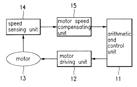
FIG. 3 is a block diagram of a control apparatus of a
drum washing machine according t:o the present invention.
C«mpared with the conventional art depicted in FIG. l, the
1 !~
CA 02238066 1998-OS-19
control apparatus of a drum washing machine according to the
present invention is additionally equipped with a motor speed
compensati:zg unit 15 for controlling a tub to rotate at
p.redetermi:zed constant speed.
Specifically, the present invention relates to a drum
w,~shing machine for controlling a motor so as to perform
cleaning c~~rresponding to each menu which is selected by a
user and a.oplied through a key pad (not shown). This drum
w,~shing machine having an arithmetic and control unit 11 for
c~~ntrollin~~ the rotation of a motor 13, a motor driving unit
1.2 for driving the motor 13 according to control of the
arithmetic and control unit 11, and a speed sensing unit 14
f~~r sensin~~ the rotational speed of the motor 13 and applying
a sensed value to the arithmetic: and control unit 11, is
a~~ditionally equipped with the motor speed compensating unit
15 for detecting a phase angle of driving voltage based upon a
difference between motor 13's rotaticnal speed values at the
c-arrent time point and the previous time point and
c~~mpensati:ng the detected phase angle so as to control the
m~~tor 13 t~a rotate at constant ~~peed while the arithmetic and
c~~ntrol unit 11 controls the motor 13 through the motor
driving unit 12 based upon the detected phase angle.
16
CA 02238066 1998-OS-19
FIG. 9 is a flow chart of an eccentricity detecting
method acc~~rding to a preferred embodiment of the present
i:zvention. The eccentricity detecting method include the step:
o>=: detecting the variation of P,PM and measuring the degree o:E
e~~centricity while positively rotating the tub at constant
speed for a predetermined time after laundry untwisting
operation is completed (S10-S40); comparing the measured
degree of eccentricity with a reference value of eccentricity
corresponding to the measured degree of eccentricity among
p:redetermi:zed different reference values of eccentricity and
df~terminin~~ whether or not to permit the eccentricity (S50-
S80); and newly performing the laundry untwisting operation o__
pf~rforming hydro-extracting operation in a manner of rotating
the tub at particular RPM according to a result of decision on
the eccentricity illustrated abc>ve (S90-5100).
The f«llowing description with reference to FIGS. 3 and ~~
concerns the hydro-extracting operation of the washing machine
a~:cording vo one preferred embodiment of the present
invention.
:20 After completion of the laundry untwisting operation, the
a_=ithmetic and control unit 11 controls the motor 13 to
positively rotate so as to positively rotate the tub until the
1 ~7
CA 02238066 1998-OS-19
tub's rotational speed sensed through the speed sensing unit
14 reaches predetermined RPM (S10).
Once the rotational speed of the tub reaches the
predetermined RPM, the arithmetic and control unit 11 control:
t:ze tub to rotate at the predetermined speed for a
predetermi:~ed waiting time and detects the variation of the
RPM during the waiting time, thereby to measure the degree of
e~~centricity (S20-S40).
At this time, there may be various methods, such as a
phase prop~~rtion and differential (PD) control, for control o:
the tub, but the drum washing machine of the present invention
df~picted in FIG. 3 controls the motor driving unit 12 using
the arithmetic and control unit 11 to gradually increase the
phase anglf=_ of the driving voltage applied to the motor 13,
thus incre<~sing the rotational ~cpeed of the motor 13. When the
rotational speed of the motor 1~~ reaches a predetermined leverL
o:E RPM, a ~~alue of the motor 13's rotational speed sensed by
the speed :sensing unit 14 is applied to the motor speed
compensating unit 15. The motor speed compensating unit 15
:?0 measures a difference between pr:.ase angles of the driving
voltages respectively applied to the rotating motor at a
current tune point and a previous time point. This difference
1 f3
CA 02238066 1998-OS-19
between the two phase angles measured. at the motor speed
c~~mpensati:ng unit 15 is applied to the arithmetic and control
u:zit 11, which controls the motor 13 through the motor driving
u:zit 12 so as to maintain the rotaticnal speed of the motor 13
at a predetermined value.
This ~~ifference between the two phase angles measured at
t:ze motor .speed compensating unit 15 corresponds to the
v,~riation between the current speed and previous speed of the
motor, that is, acceleration. A~; illustrated, the present
invention ~~ompensates the phase angle of the driving voltage
to be app lied to the motor for t:he acceleration measured at
the motor apeed compensating unit and applies a result value
o:E compensation to the arithmetic and control unit, thereby to
maintain the motor at the predetermined speed.
The mf~thod of compensating the phase angle of the driving
voltage to be applied to the motor for the acceleration
measured at the motor speed compensating unit is as follows.
When l~he current speed is lower than the previous speed,
a value obi~ained by subtracting a reference speed value from
:?0 the curreni~ speed value is subtracted from the acceleration to
compensate for the acceleration in the present invention. A
value obtained by subtracti:r~g the difference between the two
1 ~a
CA 02238066 1998-OS-19
p:zase angles, that is, accelerat:ion from the previous phase
a:zgle is a;oplied to the arithmet:ic and control unit 11 as a
p:zase angle to be newly applied to the motor. In other words,
if "current speed <. previous speed", the present invention
c~~ntrols t:~e arithmetic and control unit with the following
method of ~~ompensating for acceleration: "phase angle =
previous pzase angle - [acceleration - (present speed -
rf~ference ;speed) ] X constant" .
When the current speed is higher than the previous speed,
a value obtained by subtracting a reference speed from the
current spf~ed is subtracted from the acceleration to
c«mpensate for the acceleration in the present invention. A
v<~lue obtained by summing up the difference between the two
phase angles, that is, acceleration and the previous phase
angle is applied to the arithmetic and control unit 11 as a
phase angle to be newly applied to the motor. In other words,
i== "curreni_ speed > previous speed", the present invention
controls the arithmetic and control unit with the following
method of compensating for acceleration: "phase angle =
p,_evious phase angle + [acceleration - (present speed -
reference speed)] X constant". H.ere, the constant is a
compensatory constant for changing a value of speed into a
CA 02238066 1998-OS-19
v,~lue of t:he same unit as that of a phase angle.
Subsequently, the measured degree of eccentricity is
c~~mpared with a reference value of eccentricity corresponding
t~~ the measured degree of eccentricity among the predetermined
different reference values of eccentricity, thereby to
d~=_termine whether or not to permit the eccentricity (S50-S80).
Measuring of the degree of eccentricity of the laundry
a~Jcording to the present invention is implemented by measuring
t:ze vibration of RPM occurring in spite of controlling the
m~~tor to r~state keeping the predetermined speed using the
arithmetic and control unit. Since variation of the rotationa=L
speed caused by eccentricity of the laundry is not always
constant e~sen though the arithmetic and control unit always
controlls the rotational speed of the motor, the rotational
l.'~ speed of the motor must be continuously checked for a
predetermined period of time .
Table 1 shows the variation of RPM by subdivided ranges.
Reference :symbols, A, B, C, and D represent the absolute
values of IPM.
:?0 [Cable 1]
21
CA 02238066 1998-OS-19
RPM A B C D
Nun)'>er of articles Al B:1 Cl Dl
F~~r exampl~s, if a reference value of the RPM for detecting the
degree of eccentricity of the laundry is set to 100, the
absolute v~~lues may be subdivided as follows: A is 90, B is
1~J0, C is 103, and D is 105. To increase accuracy, A, B, C,
a:zd D may he subdivided much more elaborately.
Values of eccentricity corresponding to the number of RPL~1
v,~lues measured by the speed sensing unit 14 are registered in
the arithmetic and control unit 11 as Al, Bl, Cl and D1. The
v<~lues of eccentricity corresponding to Al, Bl, C1, and D1 are
compared with a reference value of eccentricity corresponding
to the numlser of RPM values (the measured degree of
eccentric ity) among the predetermined different levels of
reference ~aalues of eccentricity (A11, B11, C11, D11), thereb~~
tc~ determine whether or not to permit the eccentricity. The
1<~undry untwisting operation or hydro-extracting operation
where the rub rotates at the particular RPM is performed
ac: cording vo a result of the comparison (590, 5100).
As the result of the comparison, if condition, A1 > All,
is satisfied, entry into the dewatering cycle is determined
to be impo:~sible. If the condition, Al > All, is not
2 a?
CA 02238066 1998-OS-19
s~~tisfied, whether or not condition, B1 > B11, is satisfied i:~
determined. If the condition, B7_ > B11, is satisfied, the
e:ztry into the dewatering cycle is determined to be
impossible, and if the condition, B1 > B11, is not satisfied,
w:~ether or not condition, Cl > C:11, is satisfied is
determined. If the condition, C7. > C11, is satisfied, the
e:ztry into the dewatering cycle is determined to be
impossible, and if the condition, C1 > C11, is not satisfied,
w:zether or not condition, Dl > D11, is satisfied is
determined. If the condition, D1. > D11, is not satisfied, the
entry into the dewatering cycle is determined to be
impossible, and if the condition, D1 > D11, is satisfied,
finally, the entry into the dewatering cycle is determined to
bf~ possibly=.
FIG. ~ shows an algorithm c>f the hydro-extracting
o~~eration .in a washing machine according to another preferred
embodiment of the present invention. As shown in FIG. 5, the
a:Lgorithm «f the hydro-extracting operation includes: error
decision seep (5200, 5270, 5280) of comparing the number of
:?0 t_~ials for eccentricity decision with the predetermined
reference number of times and determining the entry into the
hydro-extracting operation or unbalance error; laundry
2 :3
CA 02238066 1998-OS-19
u:~twisting step (5210-5220) of performing the laundry
u:~twisting operation by reverse7_y rotating the tub at
predetermined rotational speed, if the entry into the hydro-
extracting operation is decided, and, simultaneously,
measuring the volume of the laundry in the tub with reference
t~~ the variation of RPM, thereby to produce a level of the
v~~lume of the laundry corresponding to one level of
predetermined different levels; eccentricity decision step
0230-5250) of measuring degree of eccentricity based upon the
v,~riation ~~f the RPM occurring when the tub positively rotate:
at predetermined roational speed, measuring the volume of the
l,~undry on~~e more and compensating the level of the volume of
tze laundry produced through steps 5210 and 5220 based upon
tine laundry volume newly measured and the number of trials fo=
1.5 e~:centricity decision (PC), and comparing the degree of
e~:centricity measured with a reference value of eccentricity
c~~rresponding to the compensated laundry volume level among
predetermined reference values of eccentricity of different
if=vets and determining whether c>r not to permit the
e~:centrici~ty; and regular dewatering cycle step (5260, 5290)
o:E newly pE~rfoming the error decision step (5200, 5270, 5280)
o:r perform:ing dewatering cycle i.n a manner of rotating the tub
24
CA 02238066 1998-OS-19
at particular RPM according to a result of performance of the
e~Jcentricity decision step (5260-5290).
The f~~llowing description referring to FIGS. 3 and 5
c~~ncerns operation and effect thereof in the second preferred
embodiment according to the pre:>ent invention.
Once the dewatering cycle is commenced, the driving
circuit of the washing machine of the present invention
avtempts t~~ perform the dewateri_ng operation. The number of
trials for dewatering(PC) is counted and a counted value is
scored in the arithmetic and control unit 11.
The arithmetic and control unit 11 then compares a
predetermined reference number c>f times (for example, 40
times) with the number of the trials (PC). If the entry into
the hydro-f=_xtracting operation i.s attempted more than the
1!~ reference number of times, the arithmetic and control unit
judges the status of the laundry to be in unbalance, displays
the unbalance error status through a display unit (not shown),
and contro:is peripheral devices to stop all the operation of
the washing machine (5200, 5270, S280).
:?0 If the number of trials for dewatering(PC) is less than
the reference number of times, the arithmetic and control unit.
1_L control: the motor driving ur..it so as to reversely rotate
CA 02238066 1998-OS-19
t:ze motor ~~t predetermined RPM i;for example, 50RPM).
C~~nsequently, the laundry untwi:>ting operation through which
t:~e twiste~~ laundry is untwisted by way of reversely rotating
t:~e tub is performed (5200-5210).
When the tub is controlled to rotate at predetermined
s;~eed during the laundry untwist:ing operation, the arithmetic
a:zd control unit checks variation of RPM for a predetermined
period of time and measures volume of the laundry in the tub.
T:ze arithmetic and control unit also produces a level
c~~rresponding to the volume of t:he laundry in the tub
currently .rotating from predetermined laundry volume levels
(3220).
After producing the laundry volume level corresponding to
t:ze volume of the laundry in the tub through the process
iLlustrate~~ above, the arithmetic and control unit 11 controls
t:ze motor 13 to positively rotate at predetermined RPM (for
e:~ample, 100RPM) using a phase angle of driving voltage which
i;~ compens,~ted by the motor speed compensating unit 15 so as
to rotate 'the tub and measures degree of eccentricity based
upon the variation of the RPM sensed by the speed sensing unii~
1~~ (S230) .
Subse~~uently, the arithmetic and control unit 11, after
26
CA 02238066 1998-OS-19
n~=wly measuring the volume of the laundry, compensates the
level of t:he volume of the laundry measured at the beginning
b~~sed upon the volume of the laundry newly measured and the
number of trials for dewatering(PC) and compares the measured
degree of eccentricity with a reference value of eccentricity
c~~rresponding to a level of the volume of the laundry
c~~mpensated among predetermined reference values of
e~~centricity of different level:>, thereby to determine whether
or not to .permit the eccentricity (5240-5250).
The present invention measures the volume of the laundry
two times ~~nd divides the reference values of eccentricity fo=r
deciding e~~centricity based upon the measured volume of the
l,~undry into multiple levels. Therefore, compared with the
c~~nvention~~l art which detecting eccentricity using only one
reference amount of eccentricity, the present invention using
mv~ltiple r~pference value levels of eccentricity improves
reliability in detecting the eccentricity.
Thereafter, the arithmetic and control unit 11 increases
the number of trials for eccentricity decision (PC) by 1
according to a result of comparing the reference value of the
eccentricity with the measured degree of the eccentricity and
newly compares the increased number of trials for eccentricity
2 '7
CA 02238066 1998-OS-19
d=cision (PC) with the predetermined reference number of time;
(for example, 40 times) (5290). In addition, as the result of
d=termination on the permission of th.e eccentricity, the
eccentricity is permitted, the t:ub is rotated at predetermined
RPM, there:~y to perform the regular hydro-extracting operation
(3260) .
FIG. 6 is a flow chart of t:he eccentricity detecting
m~=thod illustrating much more in detail the eccentricity
decision step (5230-5250). As sluown in FIG. 6, the
e~~centricity detecting method includes: degree of eccentricity
measuring step (s231) of controlling the tub to positively
rotate at predetermined speed after completion of the laundry
untwisting operation and measuring degree of eccentricity
b<~sed upon variation of RPM occurring when the tub rotates;
laundry volume compensation index measuring step (5232) of
mE~asuring a laundry volume compensation index used for
compensating the produced level of the volume of the laundry
by counting the case where the degree of eccentricity measure<~
av step 5231 exceeds a specified value while the number of
t_-ials for eccentricity decision (PC) is less than the
p==edetermined number of times; laundry volume level
compensating step (5233-5238) of compensating the produced
28
CA 02238066 1998-OS-19
level of t:ze volume of laundry according to the number of
trials for eccentricity decision (PC) and the laundry volume
c~~mpensati~~n index and producing a compensated laundry volume
level; and eccentricity permission decision step (5239, 5239',
S:?39", 523~~"') of comparing the measured degree of eccentricity
with a reference value of eccentricity corresponding to the
c~~mpensate~~ laundry volume leve7_ among predetermined reference
v,~lues of eccentricity of different levels, thereby to
determine whether or not to permit the eccentricity.
With .reference to FIGS. 4 t:o 6, the eccentricity
detecting method of the present invention will now be
described.
Once 'the laundry untwisting procedure (S21-5220) is
completed, the motor 13 is controlled with a phase angle of
driving voltage compensated at t:he motor speed compensating
unit 15 so as to rotate the tub at predetermined speed. At
this time, the arithmetic and cc>ntrol unit 11 senses variation
o:E motor's rotational speed, that is, variation of RPM through
the speed sensing unit 14 and measures degree of eccentricity
based upon the variation of the RPM (S231).
The e~~centricity detecting method of the present
invention measures a laundry volume compensation index (W)
2 !~
CA 02238066 1998-OS-19
u;~ed for c~~mpensating the produced level of the volume of the
laundry by counting the case where the degree of eccentricity
measured using the speed sensing unit 14 exceeds a specified
v<~lue while the number of trial~> for eccentricity decision
(~C) counted at the error decision step (5200) is less than
the predetermined number of times (s232).
For example, if the motor is controlled to rotate at the
predetermined speed of 100 RPM, the rotational speed of the
tub may irregularly change according to the eccentricity of
the tub. Hence, the eccentricity detecting method of the
present invention counts the laundry volume compensation
indexes (w) if the rotational s~>eed reaches 107 RPM more than
70 times for a predetermined period of time when the number o_~
trial for f=_ccentricity decision (PC) is 4 to 10.
l.'~ The arithmetic and control unit 11 produces a more
a~Jcurate level of the volume of the laundry by compensating
the volume level of the laundry produced at laundry untwisting
si=ep (5220) based upon the number of trials for eccentricity
decision (:?C) and the counted laundry volume compensation
indexes (w). In other words, when the level of the volume of
the laundr~~ initially produced is 4, if the number of trials
for eccentricity decision (PC) is more than a predetermined
CA 02238066 1998-OS-19
number of times (for example: 2C)), the level of the volume of
tze laundry becomes 3 through compensation operation (5233,
S:?34). whe:z the level of the vo1_ume of the laundry initially
produced is 3, if the number of trials for eccentricity
decision (PC) is more than a predetermined number of times
(Eor example: 9) and the laundry volume compensation index (w)
i,~ more than a predetermined vaI_ue ( for example, 3 ) , the leverL
of the volume of the laundry becomes 2 through compensation
operation (5235, 5237). When the level of the volume of the
laundry initially produced is 2, if the number of trials for
eccentricity decision (PC) is me>re than a predetermined numbe=r
o:E times (:for example: 15), the level of the volume of the
laundry be~~omes 1 through compensation operation (5236, 5238).
After that, the arithmetic and control unit compares the
df~gree of eccentricity measured through the speed sensing unit:
1~~ with a :reference value of eccentricity corresponding to the
cc~mpensatec~ laundry volume level. among reference values of
ecJcentricivy of different levels: predetermined according to
the producf~d compensation level of the volume of the laundry,
thereby to determine whether or not to permit the eccentricity
(:239, S23'~', 5239", 5239"') . In other words, the permission of
ec:centrici-~y depends on the degree of shaking caused by the
3 .L
CA 02238066 1998-OS-19
e~:centricity. It is checked whether the degree of eccentricity
currently measured at the speed sensing unit 14 causes
e:~cessive shaking when the washing machine performs the
regular hydro-extracting operation, with various conditions
p:redetermi:zed at the corresponding volume level of the laundry
by comparison.
FIG. 7 is a flow chart showing a preferred embodiment of
the eccentricity permission decision step (5239, 5239', 5239",
S:?39"') acc~~rding to the second embodiment of the present
invention, wherein variables, PE;AK110 and PEAK107, represent
d<~ta about degree of eccentricity which is applied to the
arithmetic and control unit 11 from the speed sensing unit 14.
When -the level of the laundry volume which is finally
produced av laundry volume level. compensating step (5233-S238j
1'~ ~:~ 4 (5233) , if the PEAK110 is 3~0 or over (5239'-5) , the
ec~centricivy is not permitted (5239-9). In addition, when the
PC is less than 8 (5239-3), if the PEAK107 (the number of RPM
values between 105 and 107) is less than 8 (5239-5), the
ec~centricil~y is permitted, and if the PEAK107 is 8 or over,
:'0 the eccent=ricity is not permitted (5239-8).
When i~he PC is 8 or over or less than 13 (5239-4), if the
PEAK107 is less than 21 (5239-7), the eccentricity is
32
CA 02238066 1998-OS-19
pf~rmitted, and if the PEAK107 is 21 or over, the eccentricity
i:~ not permitted. When the PC it> 13 or over (5239-4), if the
PEAK107 is less than 41 (5239-6), the eccentricity is
permitted, and if the PEAK107 i;> 41 or over, the eccentricity
i;~ not permitted.
When the level of the laundry volume which is finally
produced at laundry volume level. compensating step (5233-5238)
i,~ 3 (S235) and the PC does not exceed 10 (239'-1), if the
P:~AK110 is less than 6 (5239'-2), the eccentricity is
p~=_rmitted, and if the PEAK110 i:~ 6 or over, the eccentricity
i,~ not permitted.
In ad~~ition, when the PC i;> 10 or over and the W is less
t:zan 4 (5239'-3), if the PC is 21 or over, step of checking
w:zether th~s PEAK110 is less than 6 or 6 or over is newly
performed. When the PC is less than 21, if the PEAK110 is less
t:zan 30 (5239'-5), the eccentricity is permitted, and if the
P:~AK110 is 30 or over, the eccentricity is not permitted. At
this time, when the PC is 10 or over and the W is 4 or over,
the laundry volume level become~> 2 through compensation.
~0 When the level of the laundry volume which is finally
produced at laundry volume level. compensating step (5233-5238)
i;~ 2 and t:ze PC is less than 16 (239"-1), if the PEAK110 is
33
CA 02238066 1998-OS-19
lE~ss than ~5 (5239"-2), the eccentricity is permitted, and if
the PEAK11~~ is 55 or over, the eccentricity is not permitted.
Av this time, when the PC is 16 or over (239"-1), the laundry
volume lev~=1 becomes 1 through t:he compensation.
When the level of the laundry volume which is finally
produced at laundry volume level. compensating step (5233-52381
i,~. 1 and t:~e PC is 21 or over (239"'-1) , if the PEAK110 is 110
o:r over (5239"'-3), the eccentricity is not permitted, and if
t:ze PEAK110 is less than 110, the eccentricity is permitted.
When the PC is less than 21., whether the PC is 31 or ove=
i,~ newly c:zecked (239"'-2). If the PC is 31 or over, the step
of checkin~~ whether the PEAK110 is 110 or over or less than
110 is newly performed. This is for more accurate decision on
t:ze permission of the eccentrics.ty when the laundry volume
level is m~~dified into 1 from 2 through the compensation. When
t:ze PC is less than 31, if the PEAK110 is 100 or over (5239"'-
4), the ec~~entricity is not permitted, and if the PEAK110 is
less than 100, the eccentricity is permitted.
As illustrated above, the arithmetic and control unit 11
regulates the twist of the laundry or the degree of
eccentricity of the laundry at t:he eccentricity permission
decision step. When it is determined that the degree of the
34
CA 02238066 1998-OS-19
e~~centrici~ty is regulated as unbalance error does not occur
through thf~ eccentricity permistsion decision step, the
arithmetic and control unit 11 controls the motor 13 to
perform re~~ular hydro-extracting operation. However, when the
dE=gree of the eccentricity of the laundry is determined not to
bE~ regulated satisfactorily, the error decision step (S200,
S:?70, 5280) is newly performed and the dewatering cycle is
a-tempted. After all, the entry into the hydro-extracting
operation :is attempted at least a predetermined reference
number of times (for example, 40 times), that is, the degree
o:E the eccf=ntricity of the laundry is regulated at least the
predetermined number of times, occurrence of the unbalance
error in the laundry is determined. This unbalance error
s~~atus is ~~isplayed through a display unit (not shown), and
peripheral devices are controlled to stop all the operation of
the washing machine.
As il.Lustrated above, the ~>resent invention detects
volume of the laundry in a tub )r>efore commencing hydro-
e:~tracting operation, divides a process of measuring the
:?0 dE=_gree of eccentricity into multiple steps according to
laundry vo:Lume levels detected, and compensates the initially
detected laundry volume through the multiple steps, thereby to
CA 02238066 1998-OS-19
minimize mistakes in detecting the eccentricity due to an
error in dE~tection of the laundry volume. accordingly, the
p:-went invention prevents walking phenomenon of a washing
m<~chine which may occur due to excessive shaking while
performing the hydro-extracting operation .
It wi:Ll be apparent to thot;e skilled in the art that
various modifications and variations can be made in a method
and contro:L apparatus of detecting eccentricity in a drum
washing maclhine of the present invention without deviating
f:=om the spirit or scope of the invention. Thus, it is
intended that the present invention cover the modifications
and variations of this invention provided they come within the
scope of the appended claims and their equivalents.
36