Language selection

Search

Patent 2238074 Summary

Third-party information liability

Some of the information on this Web page has been provided by external sources. The Government of Canada is not responsible for the accuracy, reliability or currency of the information supplied by external sources. Users wishing to rely upon this information should consult directly with the source of the information. Content provided by external sources is not subject to official languages, privacy and accessibility requirements.

Claims and Abstract availability

Any discrepancies in the text and image of the Claims and Abstract are due to differing posting times. Text of the Claims and Abstract are posted:

  • At the time the application is open to public inspection;
  • At the time of issue of the patent (grant).
(12) Patent: (11) CA 2238074
(54) English Title: METHODS AND DEVICES FOR REPAIRING MARINE SEISMIC CABLES
(54) French Title: PROCEDES ET DISPOSITIFS POUR LA REPARATION DE FLUTES MARINES
Status: Deemed expired
Bibliographic Data
(51) International Patent Classification (IPC):
  • H02G 1/10 (2006.01)
  • G01V 1/20 (2006.01)
  • G01V 1/38 (2006.01)
  • H02G 1/04 (2006.01)
(72) Inventors :
  • AAE, BJORN (Norway)
  • THOMSON, MALLORY (United Kingdom)
  • KVALHEIM, GERHARD (Norway)
  • PETTERSEN, JAN BJORNAR (Norway)
  • SORAKER, DAG (Norway)
(73) Owners :
  • GECO AS (Norway)
(71) Applicants :
  • GECO AS (Norway)
(74) Agent: SMART & BIGGAR
(74) Associate agent:
(45) Issued: 2001-10-09
(86) PCT Filing Date: 1997-07-14
(87) Open to Public Inspection: 1998-01-29
Examination requested: 1998-05-19
Availability of licence: N/A
(25) Language of filing: English

Patent Cooperation Treaty (PCT): Yes
(86) PCT Filing Number: PCT/IB1997/000870
(87) International Publication Number: WO1998/003885
(85) National Entry: 1998-05-19

(30) Application Priority Data:
Application No. Country/Territory Date
963027 Norway 1996-07-19

Abstracts

English Abstract


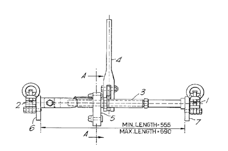
A method of replacing an electronics module in a seismic cable on the open sea, (as well as a device for use in the replacing) where
the replacement is carried out with the aid of a small boat equipped with cable rollers, the method comprising positioning the part of
the cable including the electronics module on a first and a second cable roller respectively in such a way that the electronics module and
its couplings are located between the two rollers, clamping the sections of cable on either side of the electronics module in a first and a
second clamping arrangement (1, 2) respectively, with the clamping arrangement connected together via a mechanical tensioning device
(3), moving the clamped sections of cable towards each other using the tensioning device in such a way that the tension in the seismic cable
is taken up by the tensioning device, after which the electronics module can be removed and replaced after which the tensioning device (3)
is slackened slightly and the clamping arrangement (1, 2) is released from the sections of cable before the part of the seismic cable with
the new electronics module is replaced in the sea.


French Abstract

Cette invention concerne une méthode et un dispositif de remplacement d'un module électronique de câble de prospection sismique en haute mer, le remplacement se faisant à l'aide d'une petite embarcation équipée de poulies et selon les étapes suivantes : positionnement du câble sur une première et une seconde poulies de façon que le module électronique et ses organes de montage se trouvent entre lesdites poulies, pose de serre-câble (1, 2) de part et d'autre du module électronique, montage d'un tendeur mécanique (3) reliant les deux serre-câble, rapprochement des deux serre-câble au moyen du tendeur pour donner du mou au tronçon de câble portant le module électronique, démontage et remplacement du module, desserrage léger du tendeur (3), dépose des serre-câble (1, 2) et remise à l'eau du câble équipé du nouveau module électronique.

Claims

Note: Claims are shown in the official language in which they were submitted.


CLAIMS

1. A method of replacing an electronics module in a seismic cable on the open
sea, where the replacement is carried out with the aid of a dinghy or other small boat
equipped with cable rollers, the method comprising positioning the part of the cable
including the electronics module on a first and a second cable roller respectively in
such a way that the electronics module and its couplings are located between the two
rollers, clamping the sections of cable on either side of the electronics module in a
first and a second clamping arrangement respectively, with the clamping
arrangements connected together via a mechanical tensioning device, moving the
clamped sections of cable towards each other using the tensioning device in such a
way that the tension in the seismic cable is taken up by the tensioning device,
loosening the couplings for the electronics module, slackening the tensioning device
so that the couplings can be disconnected, after which the electronics module can be
removed and replaced by a new electronics module, with the tensioning device being
re-tensioned so that the new electronics module can be fitted in the seismic cable via
its couplings, after which the tensioning device is slackened slightly and the clamping
arrangement is released from the sections of cable before the part of the seismic cable
with the new electronics module is replaced in the sea.

2. A device for use in replacing an electronics module in a seismic cable on theopen sea, where the replacement is carried out with the aid of a dinghy or other small
boat equipped with cable rollers, the device comprising on each of its sides a first and
a second clamping arrangement respectively to hold a section of seismic cable, the
clamping arrangements being linked together via at least one mechanical tensioning
device designed to move the clamping arrangements towards and away from each
other, with the separation distance between the clamping arrangements amounting to
at least the length of the electronics module with its connected couplings.

3. A device according to claim 2, wherein the mechanical tensioning device is
tensioned and slackened respectively by means of a handle mounted on the tensioning
device for this purpose.

4. A device according to claim 2, wherein two mechanical tensioning devices are
fitted, and are connected together via a chain drive for synchronous and isodynamic
pull on each of the tensioning devices, with the tensioning devices tensioned and

- 4 -

slackened respectively by means of a handle mounted on one of the tensioning devices
for this purpose.

5. A device according to claim 4, wherein the chain drive is accommodated in a
housing mounted on the tensioning devices.

6. A device according to claim 4 or claim 5, wherein the or each tensioning
device is a turnbuckle.

- 5 -

Description

Note: Descriptions are shown in the official language in which they were submitted.


CA 02238074 1998-05-19

W O 98/03885 PCT~B97/00870

METHODS AND DEVICES FOR
REPAIRING MAR~E SI~ISMIC CAR~

This invention relates to methods and devices for r~ ng marine seismic cables.
More particularly, the invention concerns a method for repl~ing an electronics
- module in a marine seisnnic cable on the open sea, where the repl~çm~nt is carried
out with the aid of a dinghy or other small boat ecluipl)ed with cable rollers. The
invention also concerns a device to carry out the method.

Marine seismic cables include a variety of electronics modules fitted between the
sections of cable and connected to these via couplin~s, usually annular col~plingc.
When a fault arises in such an electronics module, it will be necesc~ry to replace it.
The usual practice is to haul in the seismic cable and replace the electronics module
on board the towing vessel. This is a time-concl~ming and very ~Yl)e~ e operation,
especially in the case of surveys in which each vessel is towing a number of seismic
cables. If therefore it is possible for the change of the electronics module to be carried
out in situ, i.e. while the cable is in the water, both time and expense will be saved.

The aim of the invention is therefore to create a method which f~cilit~tPs the ch~nging
of an electronics module in a marine seismic cable on the open sea, and a devicewhich can be used to carry out such a method.

This aim is achieved in a~xoldallce with the invention by means of a method which is
char~ctericecl by the fact that it comprises in sequence stages to position the part of
the cable incln~ g the electronics module on a first and a second cable roller
respectively in such a way that the electronics module and its couplings are located
between the two rollers, to clamp the sections of cable on either side of the
electronics module in a iFlrst and a second cl~mI-in~ arrangement respectively, with
the clamping arrangements conn~ct~ together via a m~,ch~nir,~l ten~ioning device, to
move the cl~ pe~ sectinrl~ of cable low~u-ls each other using the tensioning device in
such a way that the tension in the seismic cable is taken up by the tensioning device,
to loosen the couplings for lthe electronics module, to slacken the t~n~inning device so
~hat the couplings can be disconnP~te~l, after which the electronics module can be
removed and replaced by a new electronics module, with the tensioning device being
ré-tensioned so that the nRw electronics module can be fitted in the seismic cable via

CA 02238074 1998-05-19

W O 98/03885 PCT~B97/00870

its couplings, after which the tensioning device is ~l~f.k~nyl slightly and the cl~mr)ing
arrangement is released from the sections of cable before the part of the seismic cable
with the new electronics module is replaced in the sea. The invention also provides a
device for use in the method, characterised by the fact that the device includes on
each of its sides a first and a second cl~mring arrangement respectively to hold a
section of seismic cable, that the clamping arrangements are linked together via at
least one mer.h~nir~l tensioning device designYl to move the clamping arrangements
towards and away from each other, with the separation ~ t~nce between the clamping
arrangements amounting to at least the length of an electronics module with its
connected coupling~.

The invention will now be explained in more detail, by ways of example only, with
reference to the attached drawings, of which:

Figure 1 shows a side elevation of a device according to the invention for use in
replacing an electronics module in a marine seismic cable while the cable is in the
sea;

Figure 2 shows in plan the device in Figure l;

Figure 3 shows a section through the device of Figure 1 taken along the line A-A;
and

Figure 4 shows a part of the device of Figure 1 seen from one end.

To carry out the method acco~lhlg to the invention, a dinghy fitted with cable rollers
is used. The dinghy is l~lln~h~1 from the towing vessel and raises the part of the
seismic cable inclllrlin~ the electronics module to be replaced. This part is pO~itiQI ed
on a first and a second cable roller respectively such that the electronics mo-llll~ and
its couplings are located between the two rollers. The sections of cable on either side
of the electronics module are then clamped in a first and a second clamping
arrangement 1, 2 respectively of a device for carrying out the ml-.thf -1 Each of the
cl~...pil-g arrangements 1, 2 is conn~ted together via a ...e~ ir~l tensioning device
3 de.~i~ned to move the cl~mping arrangt;,nen~ 1, 2 towards and away from each
other as desired. With the aid of tensioning device 3 the rl~mpe~l sections of cable
can be moved towards each other and the tension in the seismic cable taken up by the
tensioning device 3. The couplings for the electronics module can then be loosen~l,

- 2 --

CA 02238074 1998-05-19
.
O 98/03885 PCT~B97/00870
and after the ten~ionin~ device 3 has been s~ pnecl a little, they can be removed
from the seismic cable, after which the electronics module can be removed and
replaced by a new elec~ronics module, with tensioning device 3 then being re-
tPn~ic nçd so that the new electronics module can be fitted in the seismic cable via its
couplin~c. After this the ten~icnin~ device 3 is ~ PnP~l slightly again and clamping
arrangements 1, 2 are removed from the sections of cable before the part of the
seismic cable with the new electronics module is replaced in the sea.

The device for carrying out the method according to the invention will now be
dçscribed in more detail. This device is shown in the elevation drawing in Figure 1
and con~i~t~ of a first andl a second clamping arr~ngemPnt 1, 2 f~tçn~d to respective
end-pieces 6, 7 and connectel1 via the tensioning device 3. The te-n~ioning device 3
actually comprises two individual but operatively coupled together tensioning devices
3a, 3b, which are clearly shown in Figure 2 in a ~lefe~ d arrangement, and whichtake the form of turnbuckles ~screw sh~klP,s). As with the clamping arrangements 1,
2, the turnbuckles 3a, 3b are f~t~ne~l to the end-pieces 6, 7 with a s~dlion fli~t~n~e
such that the seismic cable can be placed in the cl~mpin~ arrangements 1, 2 and
between turnbuckles 3a, 3b. In the version shown in the drawing, the turnbuckles 3a,
3b are operatively connected together via a chain drive 8 shown in Figure 3 by
broken lines, which is accommodated in a housing 5. The chain drive 8 will transfer
~he movement of one turnbuckle, e.g. 3a, to the other turnbuclde, e.g. 3b, when
turnbuckle 3a, as shown in Figure 3, is operated with the aid of handle 4 by way of a
bi-directional ratchet m~h~ni~m ~not shown).

Finally, Pigure 4 shows one of the end-pieces 6, 7 of the device according to the
invention and with the clamping arrangements 1, 2 in their open and closed position
respectively, the latter being indicated by broken lines.

It should be understood that the device according to the invention does not ne~ess~rily
need to include two tensioning devices or turnbuckles 3a, 3b, but that in practice
fewer or more ten~ionin~ devices can be used. The a~ldnge,l,ent as shown in Figs. 1
to 4, however, is the ~rell~d version, as it advantageously provides an even force
applied co~xi~lly with the seismic cable when ten~ionin~ or ~ Pnin~.

Finally, it should be mentioned that the tensioning device does not have to be
implemPntyl as turnbuckles, but that other forms of tensioning device can be used,
e.g. based on hydraulics or pnpum~ti~s~

Representative Drawing
A single figure which represents the drawing illustrating the invention.
Administrative Status

For a clearer understanding of the status of the application/patent presented on this page, the site Disclaimer , as well as the definitions for Patent , Administrative Status , Maintenance Fee  and Payment History  should be consulted.

Administrative Status

Title Date
Forecasted Issue Date 2001-10-09
(86) PCT Filing Date 1997-07-14
(87) PCT Publication Date 1998-01-29
(85) National Entry 1998-05-19
Examination Requested 1998-05-19
(45) Issued 2001-10-09
Deemed Expired 2005-07-14

Abandonment History

There is no abandonment history.

Payment History

Fee Type Anniversary Year Due Date Amount Paid Paid Date
Request for Examination $400.00 1998-05-19
Application Fee $300.00 1998-05-19
Registration of a document - section 124 $100.00 1998-07-31
Maintenance Fee - Application - New Act 2 1999-07-14 $100.00 1999-06-15
Maintenance Fee - Application - New Act 3 2000-07-14 $100.00 2000-06-12
Maintenance Fee - Application - New Act 4 2001-07-16 $100.00 2001-06-06
Final Fee $300.00 2001-06-27
Maintenance Fee - Patent - New Act 5 2002-07-15 $150.00 2002-06-17
Maintenance Fee - Patent - New Act 6 2003-07-14 $150.00 2003-06-19
Owners on Record

Note: Records showing the ownership history in alphabetical order.

Current Owners on Record
GECO AS
Past Owners on Record
AAE, BJORN
KVALHEIM, GERHARD
PETTERSEN, JAN BJORNAR
SORAKER, DAG
THOMSON, MALLORY
Past Owners that do not appear in the "Owners on Record" listing will appear in other documentation within the application.
Documents

To view selected files, please enter reCAPTCHA code :


To view images, click a link in the Document Description column. To download the documents, select one or more checkboxes in the first column and then click the "Download Selected in PDF format (Zip Archive)" or the "Download Selected as Single PDF" button.

List of published and non-published patent-specific documents on the CPD .

If you have any difficulty accessing content, you can call the Client Service Centre at 1-866-997-1936 or send them an e-mail at CIPO Client Service Centre.


Document
Description 
Date
(yyyy-mm-dd) 
Number of pages   Size of Image (KB) 
Claims 1998-05-19 2 73
Abstract 1998-05-19 1 64
Description 1998-05-19 3 180
Drawings 1998-05-19 2 36
Cover Page 1998-08-26 1 61
Cover Page 2001-09-24 1 47
Representative Drawing 1998-08-26 1 5
Representative Drawing 2001-09-24 1 7
Correspondence 2001-06-27 1 41
Assignment 1998-08-26 1 45
Assignment 1998-05-19 3 99
PCT 1998-05-19 5 144
Correspondence 1998-08-11 1 29
Assignment 1998-07-31 6 193