Note: Descriptions are shown in the official language in which they were submitted.
CA 02238097 1998-0~-20
This invention relates to guide wires as commonly used
for positioning catheters through blood vessels or for
detecting blood pressure in vascular configurations.
Typically a guiding catheter may be inserted through the
vasculature and the guide wire is inserted into a blood
vessel via the guiding catheter. A balloon catheter may
then be pushed over the guide wire for proper location
into the blood vessel; alternatively, where the guide
wire is for use with a pressure measuring equipment, the
guide wire allows detection of the blood pressure, for
example in the vicinity of a stenosis.
Usually, the distal end of the guide wire is shapeable
to conform with the tortuous pathways of the blood
vessels, and the shaft of the guide wire must have a
good kink resistance to assure pushability of the guide
wire and the transmission of torque thereto. A further
requirement is that the distal end of the guide wire be
radiopaque to allow tracking the guide wire along the
vasculature.
More specifically, this invention is directed to a guide
wire comprising an elongated flexible shaft with a
proximal portion and a distal tubular portion, a coaxial
coil assembly at the distal portion of said shaft, said
coaxial coil assembly comprising a first coil having a
proximal portion and a distal portion, the proximal
portion of said first coil being inserted into the
distal tubular portion of the shaft, a second coil
having a proximal portion joined to the distal portion
of the first coil and a distal portion terminating into
a tip, and an adhesive bond for the proximal portion of
the first coil in the distal tubular portion of the
shaft.
CA 02238097 1998-0~-20
A guide wire of that kind is described in EP 0729765A1.
In the guide wire of that document, the proximal portion
of the first coil is threadedly force fitted into the
tubular distal portion of the shaft, whereby the first
coil makes a thread way into the tubular distal portion
of the shaft. In one embodiment, the proximal portion of
the first coil has ad;acent windings that are spaced
apart in order to facilitate the threadingly fitting
into the tubular portion of the shaft. This
configuration also allows the sucking and full
penetration of an adhesive into the proximal portion of
the coil to secure the definite locking of the proximal
portion of the coil in the distal portion of the shaft.
This guide wire results in a shape conforming assembly
which has all the advantages of a threaded assembly
without the need to specially machine a thread in the
tubular portion of the shaft. And as the first coil
makes the thread way into the tubular portion of the
shaft, the assembly is largely tolerance free, of course
within the limits of a given range of tolerances.
However, if the assembly between the proximal portion of
the first coil and the tubular portion of the shaft
exceeds the limits of the tolerances admitted for the
assembly, there may be problems in securing the
assembly. If the outer diametral size of the proximal
portion of the first coil is too largely bigger than the
inner diameter of the tubular portion of the shaft,
there may be difficulties to threadedly insert the
proximal portion of the first coil into the tubular
portion of the shaft, with the risk of breaking the coil
or of damaging the shaft upon doing so. When the outer
diametral size of the proximal portion of the first coil
is smaller than the inner diameter of the tubular
portion of the shaft, the threading engagement of the
coll in the tubular shaft cannot be secured; and in that
CA 02238097 1998-0~-20
case, the adhesive which is sucked and fully penetrates
into the proximal portion of the first coil cannot
safely help in securing the assembly.
It is an ob~ect of this invention to improve over the
cited art by means of a guide wire which is easy to
manufacture while assuring safe connection between the
coil assembly and the tubular portion of the shaft in a
wide range of coil and shaft tolerances. A further
ob~ect of the invention is a guide wire that is
versatile and provides excellent qualities of
pushability and shapeability.
Towards fulfilling these and other objects, the guide
wire according to the invention complies with the
definitions given in the claims.
Accordingly, when the proximal portion of the first coil
has a peripheral size providing a fit of the proximal
portion of the first coil within the distal tubular
portion of the shaft, wherein pocket means formed around
and integral with the proximal portion of the first coil
hold adhesive of the adhesive bond between the periphery
of the proximal portion of the first coil and the distal
tubular portion of the shaft, the proximal portion of
the first coil is merely inserted plug li~e into the
distal tubular portion of the shaft and the pocket means
provide a tight retention for the adhesive where it is
needed, between the periphery of the coil and the inner
3~ wall of the tubular portion of the shaft. There is
always the required minimum layer thickness for the
adhesive to secure a safe adhesive connection in a wide
range of coil and tubular shaft tolerances. The adhesive
cannot flow inside the coil and weaken the adhesive bond
of the coil into the tubular shaft. Insertion of the
coil into the tubular shaft is effortless and there are
CA 02238097 1998-0~-20
no risks of coil breaking or shaft damaging. The
assembly is stress free as long as the coil can be
loosely inserted into the tubular shaft, the coil and
shaft can be safely secured and the assembly becomes
fail proof. Manufacture of the elements of the assembly
is greatly simplified as it avoids narrow tolerances
which are always difficult to respect in tiny parts. The
shaft may be designed at will for best flexibility and
kinking resistance, with an optimal choice in varying
diameters and thickness for flexibility control. And of
course, the shaft may be tubular only at its distal
portion or fully tubular as would be required for use in
pressure measuring equipment.
When the pocket means are formed by outwardly oriented
tight recesses between consecutive turns of the proximal
portion of the first coil, advantage can be taken of the
intrinsic outer shape of the coil. And when the proximal
portion of the first coil has consecutive turns spaced
apart from one another and said pocket means are formed
by outwardly oriented tight recesses between said spaced
apart consecutive turns, a larger retention is assured
for the adhesive to further improve ease and safety of
the adhesive bonding.
The pocket means may be advantageously and simply formed
by filler means between consecutive turns of the
proximal portion of the first coil. And for further ease
of manufacture, such filler means may also extend
through the distal portion of the first coil, with the
proximal portion of the second coil overlapping the
distal portion of the first coil and bonded thereto by
said filler means. In that environment, the distal
portion of the first coil and the proximal portion of
the second coil may both have consecutive turns spaced
apart from one another and in threaded engagement with
CA 02238097 1998-0~-20
each other to facilitate positioning of the second coil
on the first coil and insertion of the filler means
therebetween.
When core means extend through the first coil wherein
said first coil is bonded to said core means by said
filler means, the pocket means are obtained by mere
introduction of the filler means between consecutive
turns of the proximal portion of the first coil as the
core means act as a support for the filler means forming
the pocket means And when the core means also extend
through the second coil and terminate into a tip
terminating the distal portion of the second coil, a
complete and sturdy coil assembly may be prepared as a
unit which will then be affixed to the shaft, thereby
preventing unwanted manipulation of the shaft during
pre-assembly of the coils.
Preferably, the filler means are formed by solder.
However, the filler means may also be formed by glue.
These and other objects, features and advantages of the
invention will become readily apparent from the
following detailed description with reference to the
accompanying drawings which show, diagrammatically and
by way of example only, a preferred but still
illustrative embodiment of the invention.
Figure 1 is a cross sectional view along the
longitudinal axis of the guide wire.
Figure 2 is a detail of Figure 1.
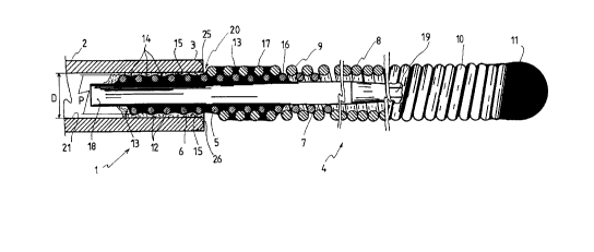
The guide wire 1 comprises an elongated flexible shaft 2
having a proximal portion (not shown3 and a distal
portion 3. As shown, the distal portion 3 is tubular.
CA 02238097 1998-0~-20
Preferably, the shaft is made of an elastic Nickel
Titanium alloy. Other materials such as for example
plastic materials are also possible.
A coaxial coil assembly 4 is affixed to the distal
portion 3 of shaft 2. This coil assembly comprises a
first coil 5 having a proximal portion 6 and a distal
portion 7, and a second coil 8 having a proximal portion
9 and a distal portion 10 ending into a brazed tip 11.
Preferably, both coils 5 and 8 are made of a high
density metal, such as for example Tungsten, for
radiopacity purposes.
The proximal portion 6 of the first coil 5 has a
peripheral size P smaller than the inner diameter D of
the distal portion 3 of shaft 2, thereby providing an
unstressed fit for the proximal portion 6 of the first
coil 5 within the distal portion 3 of shaft 2.
The consecutive turns 12 of the proximal portion 6 of
the first coil 5 are spaced apart from one another and a
solder filler 13 between said consecutive turns forms
outwardly oriented tight recesses 14 around and integral
with the proximal portion 6 of first coil 5. An adhesive
15 is inserted in recesses 14 which hold the adhesive 15
between the periphery of the proximal portion 6 of the
first coil 5 and the inner wall 21 of distal tubular
portion 3 of shaft 2.
The consecutive turns 16 of the distal portion 7 of
first coil 5 are spaced apart from one another and the
consecutive turns 17 of the proximal portion 9 of the
second coil 8, also spaced apart from one another, are
in threaded engagement with the turns 16 of first coil
5. The solder filler 13 extends through the distal
CA 02238097 1998-0~-20
portion 7 of first coil 5 and through the proximal
portion 9 of second coil 8 thereby bonding the second
coil to the first coil.
A cylindrical flexible core 18, for example of stainless
steel, extends through the first coil S which is bonded
thereto by the solder filler 13. The core 18 also
extends through the second coil 8 where it tapers as at
19 for termination (not shown) in brazed tip 11.
As shown in Figure 2, the assembly of the two coils 5
and 8 via solder filler 13 and core 18 forms a unit
ready for fixture to the shaft 2 by means of adhesive
15.
Variants are available without departing from the scope
of the invention.
For example, the consecutive turns 12 of the proximal
portion 6 of first coil 5 need not be spaced apart from
one another to form the tight recesses 14; they can be
close to one another. Same, the consecutive turns 16 of
the distal portion 7 of first coil 5 and the consecutive
turns 17 of the proximal portion 9 of second coil 8 may
be close to one another.
The pocket effect for the adhesive 15 assured by the
solder filler 13 between the turns of coil 5 may be
achieved by a tubular layer of tight material, for
example a plastic material, affixed within coil 5. Also
the pocket effect assured by recesses 14 may be obtained
by a recessed layer of tight material affixed to and
surrounding the first coil 5.
CA 02238097 1998-0~-20
The core 18 may be suppressed or limited to the first
coil or to the first coil and area of bonding of the two
coils.
The solder filler 13 may be replaced by a glue filler.
The shaft 2 may be completely tubular or tubular only at
its distal end 3.
As shown in Figure 1, there is a gap 20 between the
proximal portion 9 of second coil 8 and the distal
portion 3 of shaft 2. This gap may be reduced.
In the example shown, coil 8 has a smaller outer
diameter than the outer diameter of shaft 2. Both
elements could have substantially the same outer
diameter for a smooth transition at the junction area.
In the example shown, the distal inner and outer edges
of shaft 2 are square. It would be however preferable to
have the outer edge of shaft 2 rounded as shown in
dotted lines at 25 in Figure 1, and also to have the
inner edge of shaft 2 chamfered as shown in dotted lines
at 26 in Figure 1, whereas a better repartition of the
adhesive 15 at that level.
The peripheral size P of first coil 5 may be equal to or
slightly less than the inner diameter D of the distal
portion 3 of shaft 2.
The two coils 5 and 8 may not be in overlapping
condition.