Note: Descriptions are shown in the official language in which they were submitted.
CA 02238223 1998-OS-21
APPARATUS FOR CONTROLLING CLOSING MOTION
OF VEHICULAR SLIDING DOOR
BACKGROUND OF THE INVENTION
Field of the Invention:
The present invention relates to an apparatus for
controlling the closing motion of a vehicular sliding
door from an open position to a closed position with an
actuator.
Description of the Related Art:
Some motor vehicles incorporate a so-called power
sliding door which can be opened and closed by an
actuator such as an electric motor. The power sliding
door includes a motor unit for opening and closing a door
panel, the motor unit being mounted on a vehicle body and
operatively coupled to the door panel by an endlessly
looped cable.
If the motor unit is supplied with electric energy
at all times, then it makes the power sliding door
relatively costly because of its energy consumption even
when the door panel remains closed. To avoid the above
drawback, the power sliding door is generally of such a
type that only when the door panel is closed, electric
energy is supplied to the motor unit in response to a
signal from the door panel. Therefore, an external
switch is required to energize the motor unit when the
door panel is to move from the open position to the
- 1 -
CA 02238223 1998-OS-21
closed position.
In order to eliminate an external switch and allow
the door panel to start being power-operated with a
manual initiating action from outside of the motor
vehicle, there has been developed a vehicular door
controller as disclosed in Japanese laid-open patent
publication No. 6-344773, for example. The disclosed
vehicular door controller has an electric power unit for
selectively moving the door panel in an opening direction
to an open position or in a closing direction to a closed
position, a detector for detecting a door motion in
either the opening direction or the closing direction,
and an operating unit for energizing the electric power
unit to move the door in either the opening direction or
the closing direction depending on the detected door
motion.
While the detector can detect a door motion in
either the opening direction or the closing direction, it
is unable to identify whether the door motion is manually
triggered or caused by an accidental force such as a
shock. Usually, therefore, the operating unit starts
energizing the electric power unit after the door panel
has continuously moved a certain distance. As a result,
a person who wants to open or close the door panel needs
to move the door panel, which is relatively heavy, for a
relatively long distance until the electric power unit
starts being turned on. The person is thus subject to an
- 2 -
CA 02238223 2000-11-02
excessive load in opening or closing the door panel.
SUMMARY OF THE INVENTION
It is an object of the present invention to provide an
apparatus for controlling the closing motion of a vehicular
sliding door based on reliable detection of a manually
triggered door motion.
In a first aspect, the present invention provides an
apparatus for controlling closing motion of a vehicular
sliding door, the apparatus comprising a track positioned
below a door opening in a motor vehicle body and extending
in a longitudinal direction of the motor vehicle body, a
sliding door panel movable in opening and closing
directions along the track, and actuating means for moving
the sliding door panel.
The apparatus also comprises an operating unit mounted
on an inner lower side of the sliding door panel and
operable in response to movement of a handle on the sliding
door panel for closing the sliding door panel, a drive-
signal generator mounted on the track at an open position
of the sliding door panel, for generating a drive signal to
energize the actuating means to move the sliding door panel
in a closing direction when the operating unit operates,
and a cable, the operating unit being connected to the
handle by the cable.
The operating unit comprises a trip lever connected to
the cable and angularly movable in the longitudinal
direction within the track when the handle is moved. The
drive-signal generator comprises a sensor disposed outside
of the track, and an actuating lever inserted in the track
and angularly movable in the longitudinal direction for
actuating the sensor in response to being pressed by the
trip lever.
In a second aspect, the present invention provides
an apparatus for controlling closing motion of a vehicular
sliding door, the apparatus comprising a track positioned below
a door opening in a motor vehicle body and extending in-a
- 3 -
CA 02238223 2000-11-02
longitudinal direction of the motor vehicle body, a sliding
door panel movable in opening and closing directions along
the track, and actuating means for moving said sliding door
panel.
The apparatus also comprises an operating unit mounted
on an inner lower side of the sliding door panel and
operable in response to movement of a handle on said
sliding door panel for closing the sliding door panel, a
drive-signal generator mounted on said track at an open
position of the sliding door panel, for generating a drive
signal to energize the actuating means to move the sliding
door panel in a closing direction when the operating unit
operates, and a cable, the operating unit being connected
to the handle by the cable.
The operating unit comprises a first pusher movable in
the track when the handle is moved. The drive-signal
generator comprises a sensor disposed outside of the track,
and a second pusher disposed outside of the track and
movable for actuating the sensor in response to being
pressed by the first pusher.
The above and other objects, features, and advantages
of the present invention will become more apparent from the
following description when taken in conjunction with the
accompanying drawings in which preferred embodiments of the
present invention are shown by way of illustrative example.
BRIEF DESCRIPTION OF THE DRAWINGS
FIG. 1 is a perspective view of a motor vehicle body
which incorporates a closing motion control apparatus
according to a first embodiment of the present invention;
FIG. 2 is a perspective view of an operating unit and
a drive signal generator of the closing motion control
apparatus according to the first embodiment;
FIG. 3 is an enlarged perspective view of the
operating unit and the drive signal generator;
FIG. 4 is an enlarged perspective view of an internal
structure of the operating unit and the drive signal
generator;
- 3a -
CA 02238223 1998-OS-21
FIG. 5 is a plan view, partly cut away, showing the
manner in which the operating unit operates;
FIG. 6 is a side elevational view, partly cut away,
showing the manner in which the drive signal generator
operates;
FIG. 7 is a plan view, partly cut away, of a closing
motion control apparatus according to a second embodiment
of the present invention; and
FIG. 8 is a perspective view of an operating unit
and a drive signal generator of a closing motion control
apparatus according to a third embodiment of the present
invention.
DETAILED DESCRIPTION OF THE PREFERRED EMBODIMENTS
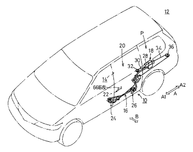
FIG. 1 shows a motor vehicle body 12 which
incorporates a closing motion control apparatus 10
according to a first embodiment of the present invention.
As shown in FIG. 1, the closing motion control
apparatus 10 comprises a track 16 positioned below a door
opening 14 in the motor vehicle body 12 and extending in
the longitudinal direction (indicated by the arrow A) of
the motor vehicle body 12, a sliding door panel 20
movable in opening and closing directions indicated by
the arrows A1, A2 along the track 16 with an actuator
unit (actuating means) 18, an operating unit 24 mounted
on an inner lower side of the sliding door panel 20 and
operable in response to movement of a handle 22 on the
- 4 -
CA 02238223 1998-OS-21
sliding door panel 20 for opening and closing the sliding
door panel 20, and a drive signal generator 26 mounted on
the track 16 at an open position P of the sliding door
panel 20, for generating a drive signal to energize the
actuator unit 18 to move the sliding door panel 20 in a
closing direction indicated by the arrow A1 when the
operating unit 24 operates.
The actuator unit 18 comprises an electric motor 28
having an output shaft on which a pair of reels is
coupled. One of the reels is connected to an end of a
cable 30 which is trained around a pulley 32 and has an
opposite end fixed to the sliding door panel 20. The
other reel is connected to an end of a cable 34 which is
trained around a pulley 36 and has an opposite end fixed
to the sliding door panel 20. When the cable 30 is wound
around the reel connected thereto which is rotated by the
electric motor 28, the sliding door panel 20 moves in the
closing direction indicated by the arrow A1. When the
cable 34 is wound around the reel connected thereto which
is rotated by the electric motor 28, the sliding door
panel 20 moves in the opening direction indicated by the
arrow A2.
The track 16 is curved transversely outwardly in a
direction indicated by the arrow B from its tip end in
the direction indicated by the arrow A1 toward the
rearward direction indicated by the arrow A2, and extends
rearward to a certain position in the longitudinal
- 5 -
CA 02238223 1998-OS-21
direction of the motor vehicle body 12. As shown in FIG.
3, the track 16 comprises a lower roller engagement plate
44 extending horizontally and an upper rail 46 extending
in the direction indicated by the arrow A and having a
substantially channel-shaped cross section.
As shown in FIGS. 2 and 3, the operating unit 24 has
a roller bracket 50 fixed to the inner lower side of the
sliding door panel 20. On an inner end of the roller
bracket 50, there are rotatably supported a first roller
52 held in rolling engagement with the roller engagement
plate 44 of the track 16 and a second roller 54 held in
rolling engagement with the rail 46 of the track 16.
As shown in FIGS. 4 and 5, a trip lever 58 is
swingably mounted by a shaft 56 in the inner end of the
roller bracket 50. The trip lever 58 is angularly
movable about the shaft 56 in the direction indicated by
the arrow A. The trip lever 58 is made of a metal such
as iron, and includes a longer arm having an end portion
of U-shaped cross section which has a curved surface 60
facing and engageable with a switch actuating lever 76
(described later on) of the drive signal generator 26.
The trip lever 58 also has a shorter arm disposed in
the roller bracket 50 and fixed to an end of the cable 64
which extends through the roller bracket 50 upwardly in
the sliding door panel 20. As shown in FIG. 2, the cable
64 has an opposite end connected to an outer handle knob
66 of the handle 22 which is mounted on an outer surface
- 6 -
CA 02238223 1998-OS-21
of the sliding door panel 22 and an inner handle knob 68
of the handle 22 which is mounted on an inner surface of
the sliding door panel 22.
A bracket 70 is mounted on the track 16 at the open
position P of the sliding door panel 20. As shown in FIG.
5, a leaf-spring stop 72 is fastened to an outer surface
of the bracket 70 by a screw, and has a bent portion 72a
projecting into the track 16. When the second roller 54
mounted on the roller bracket 50 contacts the bent
portion 72a, the sliding door panel 20 is prevented from
moving unnecessarily in the closing direction indicated
by the arrow A1.
The drive signal generator 26 is mounted in the
bracket 70. The drive signal generator 26 comprises a
microswitch (sensor) 74 disposed in an upper portion of
the bracket 70, and a switch actuating lever 76 angularly
movably mounted in the bracket 70 and extending into the
track 16. When the switch actuating lever 76 is pushed
by the trip lever 58, the switch actuating lever 76 moves
in the direction indicated by the arrow A to turn on the
microswitch 74. As shown in FIG. 4, the switch actuating
lever 76 is angularly movably supported in the bracket 70
by a shaft 78, and comprises a long arm 80 extending
downwardly and a dog 82 extending substantially upwardly
for turning on the microswitch 74. The switch actuating
lever 76 is made of a material softer than the trip lever
58, such as a resin material, for example.
_ 7 _
CA 02238223 1998-OS-21
Operation of the closing motion control apparatus 10
according to the first embodiment will be described below.
For opening the sliding door panel 20 from the
closed position, the outer handle knob 66 or the inner
handle knob 68 is manually turned. The cable 64 is
pulled in the direction indicated by arrow C (see FIGS. 4
and 5), angularly moving the trip lever 58 about the
shaft 56 in the direction indicated by the arrow D. When
the trip lever 58 is turned in the direction indicated by
the arrow D, the switch actuating lever 76 on the motor
vehicle body 12 at the open position P is pushed in the
direction indicated by the arrow A2, and turned about the
shaft 78 in the direction indicated by the arrow E,
causing the dog 82 to turn on the microswitch 74 (see FIG.
6). The microswitch 74 generates a drive signal to
energize the electric motor 28 of the actuator unit 18 to
wind the cable 34 around the reel connected thereto,
moving the sliding door panel 20 connected to the cable
34 in the opening direction indicated by the arrow A2.
For closing the sliding door panel 20 from the open
position P, the outer handle knob 66 or the inner handle
knob 68 is manually turned. The cable 64 is pulled in
the direction indicated by arrow C (see FIGS. 4 and 5),
angularly moving the trip lever 58 about the shaft 56 in
the direction indicated by the arrow D. When the trip
lever 58 is turned in the direction indicated by the
arrow D, the switch actuating lever 76 on the motor
_ g _
CA 02238223 1998-OS-21
vehicle body 12 at the open position P is pushed in the
direction indicated by the arrow A2, and turned about the
shaft 78 in the direction indicated by the arrow E,
causing the dog 82 to turn on the microswitch 74 (see FIG.
6).
The microswitch 74 transmits a drive signal to the
electric motor 28, which winds the cable 30 around the
reel connected thereto. The sliding door panel 20
connected to the cable 30 is now moved in the closing
direction indicated by the arrow Al, and hence is
smoothly closed on the motor vehicle body 12.
The electric motor 28 is automatically controlled to
reverse its direction of rotation after the sliding door
panel 20 has moved in one direction, i.e., the closing
direction or the opening direction.
In the first embodiment, when the handle 22 is
turned while the sliding door panel 20 is being closed,
the trip lever 58 and the switch actuating lever 76 are
operated to turn on the microswitch 74, which then
energizes the actuator unit 18 to open the sliding door
panel 20. Therefore, even when the sliding door panel 20
is moved in the closing direction from the open position
P under an accidental force such as an external shock,
the microswitch 74 is not turned on, and hence the
actuator unit 18 is not energized.
Accordingly, the closing motion control apparatus 10
can immediately and reliably distinguish between a
- 9 -
CA 02238223 1998-OS-21
movement of the sliding door panel 20 initiated by a
manual action and a movement of the sliding door panel 20
under an accidental external force. The actuator unit 18
can thus be accurately energized to cause the sliding
door panel 20 to be opened and closed smoothly and
reliably on the basis of the intention of a person who
wants to open and close the sliding door panel 20.
In the first embodiment, furthermore, the operating
unit 24 is housed in the roller bracket 50 on the inner
lower surface of the sliding door panel 20, and the trip
lever 58 projects into the track 16. The switch
actuating lever 76 of the drive signal generator 26 fixed
to the track 16 projects into the track 16. Therefore,
insofar as the sliding door panel 20 is closed on the
motor vehicle body 12, the operating unit 24 and the
drive signal generator 26 are isolated from the exterior
by the track 16 and the sliding door panel 20, and hence
are free from rainwater, mud, and dust while the motor
vehicle body 12 is running. As a consequence, the
operating unit 24 and the drive signal generator 26 are
protected from damage, and the microswitch 74 is also
protected from short-circuiting or the like.
The operating unit 24 has the trip lever 58
angularly movable by the handle 22, and the drive signal
generator 26 has the switch actuating lever 76 angularly
movable when pressed by the trip lever 58 and the
microswitch 74 actuatable by the switch actuating lever
- 10 -
CA 02238223 1998-OS-21
76. Therefore, the closing motion control apparatus 10
is highly simple in its entirety, and can operate
reliably with minimum failure possibilities. The trip
lever 58 and the switch actuating lever 76 which are
angularly movable do not need to be positioned highly
accurately.
The trip lever 58 includes the end portion of U-
shaped cross section which has the curved surface 60
engageable with the switch actuating lever 76. The
curved surface 60 is effective to avoid appreciable
damage to the switch actuating lever 76 when in contact
therewith. While the trip lever 58 is made of a metal,
the switch actuating lever 76 is made of a material
softer than the trip lever 58. Therefore, impact noise
produced when the trip lever 58 hits the switch actuating
lever 76 is very low in level.
The bracket 70 with the stop 72 fixed thereto is
secured to the track 16, and the drive signal generator
26 is mounted in the bracket 70. Therefore, the drive
signal generator 26 can easily be positioned without
positional errors simply when the bracket 70 is secured
to the track 16.
FIG. 7 shows a closing motion control apparatus 100
according to a second embodiment of the present invention.
Those parts shown in FIG. 7 which are identical to those
of the closing motion control apparatus 10 according to
the first embodiment are denoted by identical reference
- 11 -
CA 02238223 1998-OS-21
characters, and will not be described in detail below.
The closing motion control apparatus 100 includes an
operating unit 102 and a drive signal generator 104. The
operating unit 102 has an angularly movable link 106
connected to the cable 64. The link 106 is operatively
connected to a first pusher 110 having a pressing surface
108 which is pushed in the direction indicated by the
arrow F when the cable 64 is pulled in the direction
indicated by the arrow C by the handle 22 on the sliding
door panel 20. The drive signal generator 104 has a
second pusher 112 disposed outside of the track 16 for
actuating a sensor such as the microswitch 74 disposed
outside of the track 16 when the pressing surface 108 is
pushed in the direction indicated by the arrow F.
When the handle 22 on the sliding door panel 20 is
turned while the sliding door panel 20 is in the open
position P, the cable 64 is pulled in the direction
indicated by the arrow C. The link 106 of the operating
unit 102 is angularly moved to move the first pusher 110
toward the drive signal generator 104 in the direction
indicated by the arrow F. The pressing surface 108 of
the first pusher 110 presses the second pusher 112 in the
direction indicated by the arrow F, causing the second
pusher 112 to turn on the microswitch 74.
In the second embodiment, only when the handle 22 is
turned to turn on the microswitch 74, the actuator unit
18 is supplied with a drive signal and energized to close
- 12 -
CA 02238223 1998-OS-21
the sliding door panel 20. The actuator unit 18 is not
energized when the sliding door panel 20 is accidentally
moved under external forces due to shocks or the like.
The closing motion control apparatus 100 according to the
second embodiment offers the same advantages as those of
the closing motion control apparatus 10 according to the
first embodiment.
According to the second embodiment, particularly,
the closing motion control apparatus 100 has the first
pusher 110 having the pressing surface 108 movable in the
direction indicated by the arrow F when the handle 22 is
turned, and the second pusher 112 movable by the pressing
surface 108 in the direction indicated by the arrow F to
turn on the microswitch 74. The operating unit 102 and
the drive signal generator 104 are relatively small in
overall size and are prevented from operating in error.
FIG. 8 shows a closing motion control apparatus 120
according to a third embodiment of the present invention.
Those parts shown in FIG. 8 which are identical to those
of the closing motion control apparatus 10 according to
the first embodiment are denoted by identical reference
characters, and will not be described in detail below.
The closing motion control apparatus 120 includes an
operating unit 122 and a drive signal generator 124. The
operating unit 122 is mounted on the sliding door panel
20 and has a signal transmitter 126 disposed in the
roller bracket 50 for generating a door closing drive
- 13 -
CA 02238223 1998-OS-21
signal when the handle 22 is turned. The drive signal
generator 124 has a signal receiver 128 for detecting a
door closing drive signal generated by the signal
transmitter 126. The sliding door panel 20 houses
therein a power supply 130 such as a battery or a charger
for supplying electric energy to the signal transmitter
126.
The closing motion control apparatus 120 thus has a
signal transmission and reception system including the
signal transmitter 126 which generates a door closing
drive signal when the handle 22 is turned, and the signal
receiver 128 which detects a door closing drive signal
generated by the signal transmitter 126. Consequently,
the closing motion control apparatus 120 is highly small
in size, and prevented from operating in error. The
closing motion control apparatus 120 according to the
third embodiment offers the same advantages as those of
the closing motion control apparatus 10, 100 according to
the first and second embodiments.
As described above, the closing motion control
apparatus according to the present invention has the
operating unit mounted on the sliding door panel movable
back and forth on the track and operable when the handle
on the sliding door panel is turned, and the drive signal
generator mounted on the track at the open position of
the sliding door panel, for generating a drive signal to
energize the actuator unit to move the sliding door panel
- 14 -
CA 02238223 1998-OS-21
in the closing direction when the operating unit operates.
Since the actuator unit is energized only on the basis of
the intention of a person who turns the handle, the
actuator unit will not be energized even when the sliding
door panel is accidentally moved under external forces.
Therefore, the sliding door panel can be opened and
closed smoothly and reliably based on the intention of a
person who wants to open and close the sliding door panel.
Although certain preferred embodiments of the present
invention have been shown and described in detail, it
should be understood that various changes and modifica-
tions may be made therein without departing from the scope
of the appended claims.
- 15 -