Note: Descriptions are shown in the official language in which they were submitted.
CA 02238268 1998-OS-21 - w
- 1 -
POWER DRI7~h HOUSING EXTENSION COUPhING
Scope of the Invention
This invention relates to power tools and,
more particularly, to a ~QUpling mechanism for
securing a housing extension to a housing of a power
drill.
Bac7cground of the Invention .
Screwdriving apparatus are Known for driving
collated screws. Typical apparatus adapted to drive
collated screws include U.S. Patent 4,146,071 to
Mueller et al, issued March 27, 1979, U.S. Patent
3,930,297 to Potucel~ et al, issued January 6, 1976 and
U.S. Patent 4,404,877 to Mizuno et 'al, issued
September 20, 1993.
Each of these patents disclose a power tool
comprising a screw gun to which a driver attachment.is
removably coupled by clamping of the driver attachment
onto a forwardly extending extension of the housing
which is coaxial about a rotatable shaft. The driver
attachments are adapted to receive and successively
drive screws such as those collated together in a
plastic strip in spaced parallel relation. A useful
example of such collated screws are disclosed in U.S.
Patent 4,167,229 to Keusch et al, issued September 11,
1979 and related Canadian Patents 1,040,600 and
1,054,982 as well as U.S. Patent 4,930,630 to
Habermehl, issued June 5, 1990.
Screw guns are known which have an extension
of the housing comprising a cylindrical surface
Ap~G»L~ED SHEET
r r
CA 02238268 1998-OS-21
- 2 -
disposed coaxially about the rotating shaft of the
screw gun and onto which attachments can be clamped.
These attachments can include the driver attachments
referred to above and the mandrel extension attachment
taught by DE-A-43 25 995. Of course, this requires
complementary sizing of the cylindrical extension of
the housing and a clamp mechanism provided as part of
the attachment. Other complementary attachment systems
can be provided and are known including those in which .
the attachment is adapted for threaded engagement onto
a threaded cylindrical extension of the housing.
It is desired to secure driver attachments
to power drills having chucks which are adjustable to
coaxially clamp drill bits and the like therein:
However, power drills typically do not have a housing.
configuration which permits ease of securing of the
driver attachment. Most conventionally available
power drills do not, in fact, provide any specific
surfaces on the drill to permit securing of a driver
attachment. Moreover, the configurations of the front
portions of known power drills vary widely from
manufacturer to manufacturer and from drill to drill
with any manufacturer's line of , products. A
disadvantage thereby arises that there is no universal
coupling which is adapted to couple a driver extension
to a variety of power drills.
Typical screw guns incorporate a friction
clutch mechanism to stop rotation of a threaded
fastener to be driven when the torque exceeds a preset
amount. Power drills with chucks have the disadvantage
that they typically do not provide a clutch mechanism.
. vai~i ~~.~~ ,r
~rn ~~~FZ
CA 02238268 1998-OS-21
WO 97124205 PCT/CA96/00877
- 3 -
Summary of the Invention
To at least partially overcome these
disadvantages of previously known devices, the present
invention provides a housing extension adapted to be
coupled to the front end of a drill for securing the
housing extension fixed to the housing. The present
invention provides a mandrel to be received in a chuck
of a power drill with the mandrel carrying a thrust
bushing which is secured on the mandrel against
movement forwardly on the mandrel. A sleeve member is
provided to be sandwiched between a rearwardly
directed surface on the bearing and a forwardiy
directed surface on the housing of the drill so as to
cause the sleeve member to frictionally engage to the
housing against movement relative the housing.
An object of the present invention is to
provide a combination of a tool and a coupling for a
housing extension to be secured to a housing of the
tool.
Another object of the present invention is
to provide an improved coupling for driver attachments
for collated screwdrivers which permits the driver
attachment to be secured to a wide range of power
drills of different configurations.
Another object is to provide a driver
attachment for driving collated screws having a
universal coupling adapting the driver attachment to
be secured to many different power tools.
Another object is to provide a coupling
mechanism for attaching driver attachments to power
drills which coupling mechanism incorporates a clutch
mechanism.
CA 02238268 1998-OS-21
WO 97/24205 PCT/CA96/00877
2n one aspect, the present invention
provides a combination of a power tool having a
housing and a coupling mechanism for securing to the
housing against movement relative the housing, the
housing including a forwardly directed surface, the
power tool including:
a shaft extending forwardly from the housing
beyond the forward directed surface; and
a chuck carried on the shaft forward of the
housing,
the coupling mechanism including:
an elongate mandrel secured in the chuck for
rotation coaxially with the shaft;
a thrust bearing carried on the mandrel
preventing sliding of the bearing forwardly relative
the shaft and having a rearwardly directed surface;
and
a sleeve member disposed about the chuck
wherein the sleeve member is sandwiched between the
forwardly directed surface on the housing and the
rearwardly directed surface on the bearing such that
the sleeve is secured to the housing against movement
relative the housing.
In another aspect, the present invention
provides a coupling mechanism for securing to the
housing of a power tool about a chuck carried on a
rotatable shaft extending from a forwardly directed
surface of the tool housing, the mechanism comprising:
an elongate mandrel having a rear end
adapted to be secured in the chuck for rotation
coaxially with the shaft,
a thrust bearing carried on the mandrel
CA 02238268 1998-05-21
WO 97/24205 PCT/CA96/00877
- 5 -
forward of the rear end permitting rotation of the
mandrel within the bearing yet preventing sliding of
the bearing forwardly relative the shaft,
the thrust bearing having a rearwardiy
directed surface,
a sleeve member providing a central
cylindrical cavity adapted to be disposed about the
chuck, the sleeve member comprising inner and outer
telescoping cylindrical sections, threadably coupled
together for relative rotation to adjust the length of
the sleeve member,
a forwardmost of the cylindrical sections
engaging a rearwardly directed shoulder of the bearing
and a forwardmost of the telescoping cylindrical
section adapted to engage the forwardiy directed
surface of the tool housing whereby by adjustment of
the length of the sleeve member, the sleeve member may
be sandwiched between the forwardly directed shoulder
of the housing and the rearwardly directed surface on
the bearing to frictionally secure the sleeve member
to the housing against movement relative the housing.
Brief Description of the Drawings
Further aspects and advantages of the
present invention will become apparent from the
following description taken together with the
accompanying drawings in which:
Figure 1 is a pictorial view of the power
drill of Figure 13 shown with a coupling mechanism in
accordance with the present invention securing a
driver attachment to the drill for driving screws
collated in a strip;
CA 02238268 1998-OS-21
W~ 97/24205 PCTICA96/00877
- 6 -
Figure 2 is a schematic cross-section along
the axis of the shaft of the drill in Figure 1 and
showing the entirety of the coupling mechanism as well
as a forward portion of the drill and a rear portion
of the driver attachment;
Figure 3 is a cross-sectional view similar
to Figure 2 but showing a coupling mechanism similar
to that of Figure 2 but incorporating a clutch
mechanism;
Figure 4 shows a side cross-section similar
to that of Figure 2, however, illustrating a second
embodiment of a coupling mechanism secured to the
front of a drill having a different configuration to
that shown in Figure 1;
Figure 5 comprises a top cross-section
through the device shown in Figure 4;
Figure 6 comprises a front view of the
loclting plate illustrated in Figures 4 and 5;
Figure 7 shows a front view of the pressure
plate illustrated in Figures 4 and 5;
Figure 8 is an exploded pictorial view of
the driver attachment shown in Figure 6;
Figure 9 is a pictorial view of the opposite
side of the slide body of the driver attachment shown
in Figure 8 but with a screwstrip positioned therein;
Figure to is a schematic partially cross-
sectional view of the driver attachment of Figure 8 in
a fully extended position as seen in Figure 8 to a
plane passing through a longitudinal axis of the drive
shaft and centrally of the screws in the screwstrip;
Figure 11 is a view identical to Figure 10
but with the driver attachment in a partially
CA 02238268 1998-OS-21
WO 97!24205 PCT/CA96100877
7
retracted position in driving a screw into a
workpiece;
Figure 12 is an end view of the nose
posrtion of Figure 8; and
Figure 13 is a pictorial view of a typical
prior art power drill.
Detailed Description of the Drawings
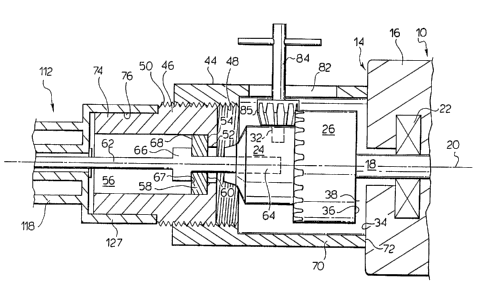
Reference is made first to Figure 13 which
shows a prior art power drill 10 having a chuck 12
which extends forwardly from a forward end 14 of the
drill housing 16.
As seen in Figure 2 which includes a cross-
section through the front end of the drill and chuck,
amongst other things, the chuck is mounted on the
forward end of a shaft 18 for rotation with the shaft
about a shaft axis 20. The shaft is schematically
illustrated as journalled by shaft bearing 22 within
the schematically indicated housing 16. As is well
known, the shaft 18 is journalled for rotation about
the shaft axis 20 in the housing 16 but is otherwise
fixed against movement relative the housing 16.
As is well known, the chuck 12 includes a
fixed chuck head 24 fixedly secured to the shaft 18
and a collar 26 which is rotatable about the shaft 18.
The collar 26 is coupled to movable clamping tong
members 28 such that rotation of the collar 26 results
~ in the tong members moving towards or away from the
shaft axis 20 so as to engage and clamp an item such
. as a drill bit in the chuck. Collar 26 carries a
toothed end face 30 and the chuck head 24 carries a
keyhole 32 such that in a known manner, a key chuck 84
CA 02238268 1998-OS-21
WO 97/24205 PCT/CA96/00877
_ g _
can have an end received in the keyhole 32 such that
on rotation of the chuck key, a toothed gear 85 on the
chuck key engages the toothed end face 30 and rotates
the collar 26 relative the chuck head 24 to release or
clamp items such as screw bits within the tong members
28.
As best seen in Figure 2, the housing 16 has
a forward end 14 with a forwardly directed housing
surface 34. The chuck has a rearmost surface 36 which
is spaced forwardly of the forwardly directed housing
surface 34 such that a gap 38 is provided therebetween
and by which the rear surface 36 of the chuck is
spaced from the forwardly directed housing surface 34.
The gap extends radially outwardly relative the shaft
axis 20.
Reference is made to Figure 1 which shows a
coupling mechanism 40 secured, on one hand, to the
power drill 10 and, on the other hand, to a driver
attachment 112 adapted to drive collated screws.
Figure 2 shows a schematic, partially cross-section
view in a plane passing through the axis of the shaft
20 of the drill and illustrating the entirety of the
coupling mechanism 40, a forward portion of the drill
to and a rear portion of the driver attachment 112.
The coupling mechanism 40 comprises a collar member
formed by rear collar segment 44 and forward collar
segment 46. Each, in effect, comprises a cylindrical
sleeve_ The rear collar segment 44 carries near its
forward end inwardly directed cylindrical threaded
surface 48 which is complementary to and threadably
engages outwardly directed cylindrical threaded
surface 50 on the forward collar segment 46. The
CA 02238268 1998-OS-21
WO 97/24205 PCT/CA96100877
_ g
collar member is thus, effectively, length adjustable
by relative rotation of the rear collar segment 44 and
forward collar segment 46 to increase or decrease the
extent to which the threaded surfaces 48 and 50
overlap.
Forward collar segment 46 has a radially
inwardly extending flange 52 at its rear end which
provides a forwardly directed shoulder 54 directed
forwardly into the cylindrical bore 56 of the forward
collar segment 46. A thrust bearing 58 is provided
within bore 56 with a rearwardly directed bearing
surface 60 engaging the shoulder 54 of the forward
collar segment 46 to prevent movement of the collar
member forwardly relative the thrust bearing 58.
An elongate mandrel 62 has its rear end 64
clamped within the chuck 12 for rotation of the
mandrel 62 with the shaft 18 about the axis 20 and
with the mandrel secured to the chuck against movement
forwardly relative the chuck, the shaft 18 and,
therefore, the drill l0.
The mandrel carries an enlarged boss 66
providing a rearwardly directed shoulder 67 which
engages a forwardly directed bearing surface 68 of
thrust bearing 58. It is clear that with the mandrel
62 secured in the chuck against movement forwardly
relative the chuck, the thrust bearing 58 is prevented
by the enlarged boss 66 from moving forwardly on the
. mandrel and the forward collar segment 46 is prevented
from forward movement by the thrust bearing 58.
With forward collar segment 46 secured to
the chuck against forward movement, by relative
rotation of the rear collar segment 44 relative the
CA 02238268 1998-05-21
WO 97/24205 PCT/CA96/0~877
- 10 -
forward collar segment 46, a rearward end 70 of the
rearward collar segment 44 carrying rearwardly
directed collar surface 72 may be urged rearwardly
into engagement with the forwardly directed housing
surface 34 with sufficient forces directed parallel
the shaft axis 20 so as to have the rearward end 70 of
the rear collar segment 44 fractionally engage the
housing 16 and secure the rearward collar segment 44
and, thus, the coupling mechanism 40 to the housing 16
of the drill against relative movement. 2n effect,
the collar member is sandwiched between the rearwardly
directed bearing surface 60 of the thrust bearing 58
and the forwardly directed housing surface 34 of the
drill.
Forward collar segment 46 is provided with
a forwardmost portion 74 having a cylindrical outer
clamp surface 76 adapted to have a complementary
cylindrical socket-forming clamp member 127 of a
housing extension 118 of the driver attachment 112
secured to the coupling mechanism 40 and, hence, to
the housing 16 of the power drill against movement
relative the power drill housing.
As shown, the collar member and,
particularly, the rear collar segment 44 is disposed
coaxially about the chuck 12 clear of engagement with
the chuck 12 so as to permit free rotation of the
chuck 12 about the shaft axis 20. The mandrel 62 is
clamped into chuck 12 and is rotatable therewith With
the thrust bearing 58 permitting the mandrel 62 to
rotate freely with the chuck. The thrust bearing 58 -
has outward radially directed surfaces which are sized
to be closely received within the bore 56 of the
CA 02238268 1998-OS-21
WO 97124205 PCT/CA96/00877
- 11 -
forward collar segment 46 and, thus, coaxially locate
the forward collar segment 46 and the coupling
mechanism 40 about the shaft axis 20.
In Figures 1 and 2, the rear collar segment
44 is shown as provided with a chuck key slot 82
provided to permit a chuck key 82 as shown to extend
radially through the slot 82 for engagement with the
keyhole 32 and the toothed end face 30 of the chuck
for tightening and loosening of the chuck. Slot 82 is
elongate in a direction parallel the axis of the shaft
so as to accommodate different locations of keyholes
in chucks of different drills.
The coupling mechanism 40, as illustrated in
Figure 2, can be secured to the drill by the coupling
mechanism including the thrust bearing 58 and the
mandrel 62 slid rearwardly coaxially relative to the
chuck such that the mandrel slides inside the chuck
and with the rear end 70 of the rear collar segment 46
to loosely engage the front end 14 of the housing 16.
In this position, the chuck key may be inserted
radially through the slot 82 and used to tighten the
chuck onto the mandrel. The chuck key is then
withdrawn. Next, by relative rotation of the forward
collar segment 46 and the rear collar segment 44, the
length of the collar member may be slightly increased
so as to frictionally urge the rearwardly directed
collar surface 72 into frictional engagement with the
forwardly directed housing surface 34 and thereby
frictionally couple the collar member and, thereby,
- the coupling mechanism 40 to the housing 16 against
relative movement. Removal can be effected by a
reverse step, notably, by reducing the length of the
CA 02238268 1998-OS-21
WO 97/24205 PCT/CA96/00877
- I2 -
collar member, rotating the loose collar member to a
position in which the slot 82 overlies the keyhole 32
and using the key chuck to release the mandrel.
It is not necessary that the slot 82 be
provided. For example, with the rear collar segment
44 removed from engagement with the forward collar
segment 46, the mandrel 62 carrying the thrust bearing
58 and the forward collar segment 46 may be clamped in
the chuck using the chuck key. Thereafter, the
forward collar segment 44 may be slid coaxially
rearwardly about the rear collar segment 46 and
threaded rearwardly relative the rear collar segment
46 into engagement with the front end 14 of the
housing 16. While the invention has been illustrated
with a chuck operative with a chuck key, the invention
is equally operative with keyless chucks.
Reference is now made to Figure 3 which
shows a cross-section similar in many respects to
Figure 2, however, showing a modified form of the
forward collar segment 46 adapted so as to provide a
clutch mechanism.
Figure 3 schematically shows a socket-
forming member 86 journalled in bore 56 for rotation
about axis 20 by bearings generally indicated 88 and
90. The socket-forming member 86 has at its front
end, a hexagonal socket 87 adapted to receive known
hexagonal bits for screwdrivers therein. A rearward
end of the socket-forming member 86 is provided with
frustoconical surfaces 92. The socket-forming member
86 is fixed within the forward collar segment 46 -
against movement forwardly or rearwardly.
The mandrel 62 carries axially extending
CA 02238268 1998-OS-21
WO 97/24205 PCT/CA96/00877
- 13 -
splines 94. A clutch member 96 is provided on the
mandrel axially slidable relative the mandrel by
reason of the clutch member having axially extending
keyways corresponding to the splines 92. Clutch
member 96 has a forwardmost frustoconical surface 97
adapted to mate with and to be complementary to the
rear conical surface 92 of the socket-forming member
86.
A disc spring 98 engages a rearwardly
directed shoulder 100 formed in the forward collar
segment 46 so as to bias the clutch member 96
forwardly into engagement with the socket-forming
member 86. The disc spring 98 urges the clutch member
96 into the socket-forming member 86 with sufficient
pressure such that the frictional engagement between
the conical surfaces 92 and 97 transmit rotational
forces from the clutch member 96 to the socket-forming
member 86 and, hence, on, for example, to a bit
engaging a screw to be driven into a workpiece. To
the extent that a screw may be fully driven into a
workpiece and the torque required to continue to
rotate the screw substantially increases, the
frictional engagement between the clutch member 96 and
the socket-forming member 86 will not be sufficient
for continued rotation of the socket-forming member 86
having regard, amongst other things, to the forces
applied by the disc spring 98. Thus, on a screw being
_ fully driven into a workpiece, the clutch mechanism
serves to disengage a bit engaging the screw from
_ rotation with the shaft 18.
The embodiment of the coupling mechanism 40,
illustrated in Figure 3 and including a clutch
CA 02238268 1998-05-21
WO 97/24205 PCT/CA96/00877
- 14 -
mechanism, is particularly adapted to be secured to a
power drill and, in effect, convert the power drill
into a screw gun which incorporates a clutch
mechanism. While only one form of a clutch mechanism
is shown, many other forms of clutch mechanisms may be
utilized.
The forward end of the forward collar
segment 46 is provided with outer cylindrical surface
76 about which a driver attachment such as illustrated
in Figure 1 can be attached.
Reference is now made to Figures 4, 5, 6 and
7 which show a second embodiment of a coupling
mechanism 4o in accordance with the present invention
and in which similar reference elements are also used
to refer to similar elements.
Figure 4 illustrates a schematic cross-
sectional side view, somewhat similar to that shown in
Figure 2, while Figure 5 shows a top view in a plane
perpendicular to the view of Figure 4.
As seen, the rear collar segment 44 is
provided radially inwardly of the forward collar
segment 46 with the rear collar segment 44 having
external cylindrical threaded surfaces 48 and the
forward collar segment 46 having internal cylindrical
threaded surfaces 50. The forward collar segment 46
has a rearwardly opening cylindrical bore sized to
receive the thrust bearing 58 therein. As best seen
by a comparison of Figures 5 and 6, a bearing locking ,
pressure 12o plate is provided rearward of the thrust
bearing 58 and, in effect, the bearing plate 120
provides forwarding directed shoulder surfaces 54 to
be engaged by the rearwardly directed bearing surface
CA 02238268 1998-OS-21
WO 97/24205 PCT/CA96l00877
- 15 -
60. The bearing plate 120 is illustrated in a front
view in Figure 7 and is provided with a central
opening 122 adapted to be disposed about the mandrel
62 and with the opening 122 extending as a slot 124 to
one side. The forward collar segment 46, in effect,
has a radially extending slotway 126 sized to receive
the bearing plate 120 and to permit the bearing plate
120 to be removed or inserted by sliding inward and
outward of the slotway 126 in directions indicated by
the arrow 128 in Figure 5. Bearing plats 120 is
provided with a small opening 130 to assist in
engagement of the bearing plate for removal.
In the embodiment of Figures 5 and 6, the
thrust bearing 58 is secured as in a forced fit
relation about the mandrel 62 so as to prevent the
thrust bearing from being moved forwardly relative the
mandrel.
Figures 5 and 6 show a configuration of the
front end of the housing of a drill 10 which differs
from that in shown in Figures 3 and 4. In Figures 5
and 6, the housing 16 does not extend radially of the
shaft axis beyond an outermost radius of the chuclt_
To permit the rear end 70 of the rear collar segment
44 to engage the forwardly directed housing surfaces
of the housing 16 about the shaft, a pressure plate
132 is provided disposed in the gap 38 between the
rear surface 36 of the chuck and the forwardly
directed housing surface 34. The pressure plate 132
has a central opening 134 adapted to be coaxially
- received about the shaft 18 radially spaced therefrom.
The opening 134 opens radially as a slot 136 open to
the side of the pressure plate 132 so as to permit the
CA 02238268 1998-OS-21
WO 97/24205 PCT/CA96/00877
- 16 -
pressure plate I32 to be located in a desired position
by sliding radially into the gap 38. The pressure
plate 132 is of a thickness which is less than the
thickness of the gap as measured parallel the shaft
axis 20 such that on the pressure plate 32 being urged
rearwardly into the housing 16, the pressure plate is
free and clear of the chuck 12 and the shaft 18 which
are free to rotate.
As seen in Figures 5 and 6, the front end 14
of the rear collar segment 44 is provided with a
recessed annular step shoulder 138 sized to match the
outer perimeter of the pressure plate 132 and assist
in coupling the pressure plate 132 to the rear collar
segment 44.
In use of the coupling mechanism 40 of
Figures 5 and 6, with the mandrel 62 coupled in the
chuck and the plates 120 and 132 positioned as shown
in Figures 5 and 6, by relative rotation of the rear
collar segment 44 and the forward collar segment 46,
the collar member is sandwiched between the thrust
bearing 58 and the housing 16 by reason of transfer of
pressures from the bearing plate 120 to the forward
collar segment 46 to the rear collar segment 44 and to
the pressure plate 132. In this manner, the pressure
plate 132 and, hence, the entire coupling mechanism
may be frictionally urged into the forwardly directing
housing surfaces of the housing 16 so as to secure the
coupling mechanism 40 to the housing 16 against .
relative movement.
Securing of the coupling mechanism 40 to a
drill may be accomplished in the following steps.
Firstly, the mandrel 62 carrying merely the thrust
CA 02238268 1998-OS-21
WO 97/24205 PCT/CA96/00877
- I7 -
bearing 58 may be secured in the chuck in a known
manner. Next, the forward collar segment 46 with the
rear collar segment 44 is readily coupled about the
mandrel by sliding axially about the mandrel
rearwardly until the thrust bearing is suitably
engaged within the bore 56 in the forward collar
segment 46. In this position, the bearing plate 120
may be slid radially into the slotway 126 to be
disposed rearward of the thrust bearing 58 as shown in
Figures 4 and 5. Next, the pressure plate 132 may be
slid radially into the gap 38 between the chuck 12 and
the housing 16 and located in the step shoulder 238 of
the rear collar segment 44. Subsequently, by
increasing the length of the collar member by relative
rotation of the forward collar segment 46 and the rear
collar segment 44, the coupling mechanism may be urged
into frictional engagement with the housing 16.
The coupling mechanism 40 illustrated in
Figure 4 also includes a clamp surface 76 about which
driver attachment 112 as illustrated in Figures 2 may
be secured.
It is to be appreciated that a pressure
plate 132 as illustrated in Figures 5, 6 and 8 may
also be adapted for use with a coupling mechanism as
illustrated in Figure 4. Preferably, the coupling
mechanism of either Figure 2 or Figure 4 would be
provided with suitable pressure plates which pressure
- plates, such that the coupling mechanism 40, with or
without the pressure plates, is adapted for coupling
- to a wide variety of configurations of drill housings.
It is to be appreciated that with some drill housing
configurations, even though the front end of the drill
CA 02238268 1998-OS-21
WO 97/24205 PCT/CA96/00877
- 18 -
housing may extend radially beyond a maximum diameter
of the chuck, it may be advantageous or necessary to
use a pressure plate 132 so as to permit engagement
with forwardly directed housing surfaces 34 which
assist in transferring forces between the rear collar
segment 44 and the housing 16 parallel the shaft axis
2o and without tending to place the forward collar
segment 44 in an orientation which is not disposed
coaxially relative the shaft axis 20.
The preferred pressure plate 136 illustrated
is merely a flat plate, preferably of metal. Such
pressure plates could have a rearwardly directed
surface which is customized for particular drills and
provide a three-dimensional mirror image of the
forwardly directed surface 34 of the drill with a rear
surface adapted to engage with the rear sleeve segment
44.
The illustrated coupling members each
provide a cylindrical clamp surface 76 for coupling,
for example, of a driver attachment illustrated as
112. It is to be appreciated that many other
mechanisms may be provided on the coupling mechanism
4o to permit various power takeoff devices to be
attached to the coupling mechanism 4o and thereby form
extensions of the housing 16 of the drill which
extensions are fixed to the housing 16 of the drill
against relative rotation. In the embodiments shown
in Figures 2 and 4, not only could the surfaces -
indicated as 76 provide a clamp surface but, also, the
outermost cylindrical surface indicated as 140 could
also provide a clamp surface. of course, any clamping
surfaces need not be cylindrical but merely need to be
CA 02238268 1998-OS-21
WO 97/24205 PCT/CA96/00877
- 19 -
complementary to coupling sockets or other mechanisms
of any housing extensions desired to be secured.
Figures 1 and 2 illustrate an embodiment in
which a driver attachment 112 is secured via the
coupling mechanism 40 to the power drill 10. It is to
be appreciated that the coupling mechanism could be
provided as an integral part of the driver attachment.
Such a configuration is, of course, illustrated in
Figure 3 in which the coupling mechanism includes as
a functional component, a clutch mechanism. It is to
be appreciated that a unitary element could be
provided incorporating driver attachment 112, the
clutch mechanism and the coupling mechanism 40.
Preferred driver attachments which may be
secured to a power drill using the coupling mechanism
in accordance with the present invention are
attachments which are relatively lightweight. It is
to be appreciated that in use of a driver attachment
such as 112, the coupling mechanism principally needs
to provide a sufficiently strong to the coupling of
the housing as to support the weight of the driver
attachment 112. In use of a driver attachment 112 to
drive screws, principal forces being applied between,
for example, a screw to be driven and the tool, are
applied directly through the shaft, chuck and mandrel
without substantially any forces- fending-~o--urge-the
coupling mechanism 40 forwardly off the housing 16 or
- tending to rotate the coupling mechanism 40 relative
the housing 16. However, preferred driver attachments
112 would be those attachments which are relatively
lightweight. The coupling mechanism may be used for
coupling attachments which translate the rotary motion
CA 02238268 1998-OS-21
WO 97/24205 PCT/CA96/00877
into other motions such as' orbital sanding and
reciprocal sawing motions.
Reference is now made to Figure 7 which
shows a driver attachment 112. The driver attachment
112 is adapted to receive a collated screwstrip 114
with spaced screws 116 to be advanced by the driver
attachment 112, located in alignment with a
screwdriver bit and subsequently driven into a
workpiece on the user urging the drill 1o into a
workpiece. The structure of the preferred driver
attachment 112, shown in Figure 1, is described below
with reference to Figures 8, 9, 10, 11 and 12.
In overview, the driver attachment 112 has
a rearwardly directed socket 127 complementary to the
cylindrical surface 76 on the coupling mechanism for
coupling of the driver attachment 112 to the drill lo
and with a driver shaft 134 to be received in the
chuck 12. The driver attachment has a housing 118
which is secured to the housing 16 of the drill 10 via
the socket 127. A slide body 120 is slidable relative
the housing coaxially about the drive shaft 134 for
reciprocal inward and outward movement and i.s biased
by a spring 138 outwardly away from the housing 118.
The slide body carries a guide mechanism for guiding
screws in the screwstrip into and maintaining a screw
to be driven in axial alignment with the drive shaft
134 and a mechanism for successively advancing screws
in the screwstrip.
Dr3.ver Attachment
Reference is made to Figure 8 showing an
exploded view of major components of the driver
CA 02238268 1998-OS-21
WO 97/24205 PCT/CA96/00877
- 21 -
attachment 112 as housing 118 and a slide body
comprising a rear portion 122 and a removable nose
portion 124. Figures 10 and 11 show in cross-section
the interaction of these components.
As seen in Figure 10, the rearmost end 126
of the housing 118 has a rearwardly directed socket
127 with a longitudinal slot 128 in its side wall to
receive and securely clamp the housing 118 onto the
cylindrical surface 76 of the coupling mechanism 40 so
as to secure the housing 118 of the driver attachment
to the housing 16 of the drill 10 against relative
movement. The chuck 12 of the drill releasably
engages a hexagonally shaped end of the driver shaft
134 in known manner. The housing 118 is provided with
a lateral flange 136 at its rear end to which a known
screwstrip containing cartridge 119 may optionally be
secured in a conventional manner as shown in Figure
10.
As seen in Figure 30, the slide body 120 is
slidably received in the housing 118 with the driver
shaft 134 received in a bore passing through the rear
portion 122 and nose portion 124 of the slide body
120. A compression spring 138 disposed between the
housing 118 and the rear portion 122 coaxially about
the driver shaft 134 biases the slide body away from
the housing 118 from a retracted position towards an
extended position. As shown, the spring 138 is
disposed between the housing 118 and the rear portion
122. Slide stops 125, best shown in Figure 8, are
secured to the rear portion 122 of the slide body.
Two slide stops 125 slide in two longitudinal slots
140 on each side of the part cylindrical side wall 142
CA 02238268 1998-OS-21
WO 97!24205 PCT/CA96/00877
- 22 -
of the housing 118 to key the rear portion 122 of the
slide body to the housing 118 against relative
rotation and to prevent the slide body being moved out
of the housing 118 past a fully extended position.
The rear portion 122 comprises a generally
cylindrical element 144 with a radially extending
flange element 146 on one side. A lever 148 is
pivotally mounted to the flange element 146 by bolt
150 normal to a longitudinal axis 152 which passes
centrally through the drive shaft 134 and about which
the drive shaft is rotatable. Lever 148 has a forward
arm 154 extending forwardly to its front end 156 and
a rear arm 158 extending rearwardly to its rear end
160. A cam follower 162 has its forward end 163
mounted to the rear end 160 of the rear arnt 158 by a
bolt 164 being received in a slot 165 extending
longitudinally in the rear end of the rear arm 158.
The cam follower 162 has at its rear end 166 two cam
rollers 167 and 168 rotatable on pins parallel to the
axis of bolts 150 and 164.
As seen in Figures 8 and l0, the housing 118
carries a caroming channel 170 in which the cam rollers
167 and 168 are received. The caroming channel 170 is
disposed to one side of the driver shaft 134 and
extends generally parallel thereto. The .caroming
channel 170 has opposed caroming surfaces 171 and 172
at least partially closed by side walls 173 and 174.
The caroming channel 170 extends rearwardly
beside the socket 127 of housing 118 and, thus,
rearwardly past the cylindrical support surface 82 of .
the screw gun 10 to one side thereof. This
configuration permits the use of a housing 118 which
CA 02238268 1998-OS-21
WO 97/24205 PCT/CA96/00877
- 23
is of a lesser length parallel longitudinal axis 152
for a given length of the cam follower 162 and of the
lever 148, rearward of bolt 150.
A spring 169 wound about bolt I50 is
disposed between the flange element 146 and the
forward arm 154 of the lever I48 to bias the lever in
a clockwise direction as seen in Figure 10. The
effect of spring 169 is to urge the cam roller 167
into engagement with cam surface 171 and to urge cam
roller 168 into engagement with cam surface 172.
With relative sliding of the slide body 120
and the housing 118 between the extended and the
retracted positions, the cam follower 62 translates
the relative movement and positioning of the slide
body 120 and housing 118 into relative pivoting and
positioning of the lever 48 about the axis 151. The
ability of bolt 164 to slide longitudinally in the
longitudinal slot 65 provides a lost motion linl~age as
is known and has advantages such that the relative
timing of pivoting of the lever 148 varies as compared
to the relative location of the slide body 120 and
housing 118 in moving towards an extended position as
contrasted with moving towards a retracted position.
The nose portion 124' has a generally
cylindrical screw guide element or guide tube 175
arranged- cgenera-fly -coaxia3l~ ai~out - lonr~itudinal- -axis
152 and a flange°lil~e screw feed channel element 176
extending radially from the guide tube 175.
The guide tube 175 has a cylindrical portion
177 at its rear end with a cylindrical exterior
surface sized to be closely received, preferably in a
friction fit, within a forwardly opening cylindrical
CA 02238268 1998-OS-21
WO 97124205 PCT/CA96/00877
- 24 -
bore 178 in the forward end of the rear portion 122.
A radially extending key 18o is provided to extend
from the cylindrical portion 177 of the nose portion
124 to be received in a correspondingly sized keyway
slot 182 in the rear portion 122 as best seen in
Figure 1o to secure the nose portion 124 to the rear
portion 122 against relative pivoting about the
longitudinal axis 152.
The guide tube 175 has a cylindrical bore or
guideway 182 extending axially through the guide tube
with the guideway 182 delineated and bordered by a
radially extending cylindrical sidewall 183 and open
at its forward axial end 184 and at its rearward axial
end 185.
The guide tube 175 has a rearward section
adjacent its rear end 185 in which the side wall 183
extends 360° about the guideway 182. Forward of the
rearward section, the guide tube has a forward section
best seen in Figure to and which has an access opening
86, shown in the drawings as being on the right hand
side of the guide tube 175. Screw access opening 286
is provided to permit the screwstrip 114 including
retaining strip 113 and screws 116 to move radially
inwardly into the guideway 182 from the right as seen
in Figures l0 and 1I. Each screw, preferably, has a
head 117 with a diameter marginally smaller than the
diameter of the side wall 183. It follows that where
the head of the screw is to enter the guideway 182,
the screw access opening must have a circumferential
extent of at least 180°. Where the shank 208 of the
screw is to enter the guideway, the screw access
opening may have a lesser circumferential extent.
CA 02238268 1998-OS-21
WO 97/24205 PCT/CA96/00877
- 25 -
In the forward section, the side wall 183 of
the guide tube 175 engages the radially outermost
periphery of the head 117 of the screw 116, to axially
locate the screw head 117 coaxially within the
guideway 182 in axial alignment with the drive shaft
134. In this regard, the side wall 183 preferably
extends about the screw sufficiently to coaxially
locate the screw head and thus, preferably, extend
about the screw head at least 120°, more preferably,
at least 150° and, most preferably, about 180°.
An exit opening 187, shown towards the left
hand side of the guide tube 175 in Figures 10 and 11,
is provided of a size to permit the spend plastic
strip 113 from which the screws 116 have been driven
to exit from the guideway 182. Forwardly of the exit
opening 187, the side wall 183 of the guide tube 175
is shown as extending greater than about 180° about
the longitudinal axis 152 so as to continue to provide
a side wall 183 which can assist and positively
coaxially guiding the head 117 of a screw 116 being
driven.
The screw feed channel element 176 is best
seen in Figures 9 and 10 as providing a channelway 188
which extends radially relative the longitudinal axis
152 to intersect with the guideway 182 in the guide
tube 175. In this regard, the channelway 188 opens to
the guideway 182 as the screw access opening 186. The
channelway 188 provides a channel of a cross-section
similar to that of the screw access opening 186 from
_ the screw access opening 186 to a remote entranceway
opening 190. The channelway 188 is defined between
two side walls 191 and 192 joined by a top wall 193.
CA 02238268 1998-OS-21
WO 97/24205 PCT/CA96/00877
- 26 -
The major side wall 191 is shown as extending from the
heads 117 of the screws 116 forwardly to at least
partially behind the plastic retaining strip 213. The
lesser side wall 192 is shown as extending from the
heads 117 of the screws 116 forwardly to above the
plastic strip 113. The side walls 191 and 192 define
the channelway 188 with a cross-section conforming
closely to that of the screwstrip 114 and its strip
213 and screws 116 with an enlarged Width where the
heads of the screws are located and an enlarged width
where the retaining strip 113 is provided about the
screws. The side walls 191 and 192 also have a
enlarged funnelling section at the entranceway opening
19o which tapers inwardly to assist in guiding the
screw strip to enter the channelway.
As best seen in Figure 9, the major side
wall 191 is provided on its exterior back surface with
a raceway 194 extending parallel the channelway 188
and in which a shuttle 196 is captured to be slidable
towards and away from the guide tube 175 between an
advanced position near the guide tube and a withdrawn
position remote from the guide tube. The shuttle 296
has a rear surface 197 in which there is provided a
rearwardly directed opening 198 adapted to receive the
front end 156 of the forward arm 154 of lever 148 so
as to couple the shuttle 196 to the lever 148 for
movement therewith.
Shuttle 196 carries a pawl 199 to engage the .
screwstrip 114 and with movement of the shuttle 196 to
successively advance the strip one screw at a time.
As seen in Figure 12, the shuttle 196 has a fixed post
200 on which the pawl 199 is journalled about an axis
CA 02238268 1998-OS-21
WO 97/24205 PCT/CA96/00877
- 27 -
parallel the longitudinal axis 152 about which the
driver shaft 34 rotates. The pawl 199 has a strip
pusher arm 201 which extends through a slot 203 in the
major side wall 191 to engage and advance the
screwstrip. The pawl 199 has a manual release arm 202
away from pusher arm 201 and which extends out through
a slot 204 in the shuttle 199. A torsional spring is
disposed about post 200 between pawl 199 and shuttle
196 and urges the pusher arm 201 clockwise as seen in
Figure 12. The spring biases the pusher arm 201 into
the screwstrip 114. The engagement of release arm 202
on the right hand end of slot 204 limits the pivoting
of the pawl 199 clockwise to the position shown in
Figure 12.
The pusher arm 2 O1 of the pawl 19 9 has a cam
face 207. On the shuttle moving away from the guide
tube 175 towards the withdrawn position, i.e., to the
left in Figure 12, the cam face 207 will engage the
screws 116 and/or the strip 113 and permit the pusher
arm 201 to pivot about post 200 against the bias of
spring so that the pusher arm 201 may move with the
shuttle to the left.
The pusher arm 201 has an engagement face
208 to engage the screws 116 and/or strip 113. On the
shuttle moving towards the guide tube 175 towards the
advanced position, i.e., to the right in Figure 12,
the engagement face 208 will engage the screws 116
and/or strip 113 and advance the screwstrip to the
right as seen in Figure 12 so as to position a screw
116 into the guideway 182 in a position to be driven
and to hold the screwstrip 114 against movement
towards the left.
CA 02238268 1998-OS-21
WO 97/24205 PCT/CA96/00877
- 28 -
The release arm 202 permits manual
withdrawal of the screwstrip 114. A user may, with
his finger or thumb, manually pivot the release arm
202 against the bias of spring so that the pusher arm
201 and its engagement face 208 is moved away from and
clear of the screwstrip 114 whereby the screwstrip may
manually be withdrawn as may be useful to clear jams
or change screwstrips.
With the nose portion 124 coupled to the
rear portion 122, the lever 148 couples to the shuttle
196 with the forward arm 154 of lever 148 received in
the opening 198 of the shuttle 196. Sliding of the
slide body 12o and the housing 118 in a cycle from an
extended position to a retracted position and then
back to an extended position results in reciprocal
pivoting of the lever 148 about axis 151 which slides
the shuttle 196 between the advanced and withdrawn
position in its raceway 194 and hence results in the
pawl 199 first retracting from engagement with a first
screw to be driven to behind the next screw 116 and
then advancing this next screw into a position to be
driven.
The nose portion 124 is removable from the
rear portion 122. The nose portion 124 and rear
portion 122 may be coupled together by axially
inserting the cylindrical portion 77 of the guide tube
175 into the bore 178 in the rear portion 122 with the
key 280 aligned with the keyway slot 182 and with the
front end 156 of the forward arm 154 of the lever 148
aligned with the opening 198 in the shuttle 196.
Thus, the removable nose portion 124 may be coupled to
the rear portion 122 merely by axially aligning the
CA 02238268 1998-OS-21
WO 97/24205 PCTlCA96/00877
- 29 -
nose portion and the rear portion and moving the two
elements together in a direction parallel the
longitudinal axis 152.
With the nose portion 124 held on the rear
portion 122 by a friction fit, the nose portion 124
can manually be removed by a user merely by the manual
application of force. The nose portion 124 is
removable from the rear portion 122 without
disassembly or uncoupling of any of the remainder of
the screwdriver assembly 110. Thus, the nose portion
124 is removable without uncoupling of the rear
portion 122 relative any of the housing 118, spring
138, drill 10, driver shaft 134 or the screw feed
activation mechanism comprising, amongst other things,
the lever 148 and cam follower 162 and without
uncoupling of the cam follower 162 in caroming channel
170 of the housing 118.
The nose portion 124 carries the guide tube
17.5 with its screw locating guideway 182, the screw
feed channel element 176 with its channelway 188, and
screw feed advance mechanism with the reciprocating
shuttle 196 and pawl 199 to advance the screwstrip 114
via the channelway 188 into the guideway 182. Each of
the guideway 182, channeiway 88 and shuttle 196 are
preferably customized for screwstrips and screws or
other fasteners of a corresponding size. In this
context, size includes shape, head diameter, shaft
diameter, retaining strip configuration, length,
spacing of screws along the retaining strip and the
presence or absence of washers, amongst other things.
Different nose portions 124 are to be configured for
different screwstrips and screws. The different nose
CA 02238268 1998-OS-21
WO 97/24205 PCT/CA96/U0877
- 30
portions 124 are each compatible with the same rear
portion 122 and are readily exchangeable so as to
permit the driver attachment to be readily adapted to
drive different screwstrips and screws.
Many changes can be made to the physical
arrangement of the nose portion 124 to accommodate
different screws and fasteners. For example, the
cross-sectional shape of the channelway 288 can be
changed as can the diameter of the guideway 182. The
length of the side walls 191 and 192 about the
channelway 188 can be varied to accommodate different
size screws which may require greater or lesser
engagement.
To adjust for different spacing between
screws in different screwstrips, the stroke of the
shuttle 196 in reciprocating back and forth can be
shortened or lengthened by varying the distance from
the axis 151 of the lever 148 to where the shuttle 196
engages the forward arm 154 of the lever 148. For
example, placing the same shuttle 196 in a raceway 194
spaced further from the axis 151 will increase the
length of the stroke of the shuttle 196 for the same
arc of pivoting of lever 148. Similarly, using the
same shuttle 196 in the same raceway 194 but having
the opening 198 in the shuttle 196 to engage the lever
148 farther from the axis 151 will also increase the
length of the stroke of the shuttle 196 for the same
arc of pivoting of lever 148.
In contrast with the removable nose portion
124 which is intended to be provided in many different
replaceable configurations, the remainder of the
driver attachment is preferably of a constant
CA 02238268 1998-OS-21
WO 97124205 PCT/CA96/00877
- 31 -
unchanged configuration. In this regard, the
remainder of the driver attachment may be
characterized by the housing 118, rear portion 122 of
the slide body 120, drive shaft 134 and spring 138
together with a screw feed activation mechanism
comprising the lever 148 and cam follower 162
interacting between the rear portion 122 and the
housing 118. This screw feed activation mechanism is
activated by relative movement of the housing 118 and
rear portion 122 and serves to engage and move the
screw feed advance mechanism comprising the shuttle
196 and pawl 199 carried on the nose portion 124.
The construction of the housing 118 and
slide body 120 provide for a compact driver
attachment.
The housing 118 has a part cylindrical
portion formed by side wall 401.
The slide body 120, as been seen in Figure
9, comprising the rear portion 122 and nose portion
I24, has a part cylindrical portion of a uniform
radius sized to be marginally smaller than the side
wall 401 of the housing 118. The side wall 401
extends circumferentially about the part cylindrical
portion of the slide body 120 to retain the slide body
120 therein.
The housing has a flange portion 402 which
extends radially from one side of the part cylindrical
portion and is adapted to house the radially extending
flange 146 of the rear portion 122 and the screw feed
activation mechanism comprising the caroming channel
170 interacting with the lever 148 and cam follower
162. The flame portion 402 is open at its front end
CA 02238268 1998-OS-21
WO 97124205 PCT/CA96/00877
- 32 -
and side to permit the screw feed channel element 176 ,
to slide into and out of the housing 118.
Concentrically located about the drive shaft 134 is
the spring 138, the part cylindrical portions of the
slide body 120, and the part cylindrical portions of
the housing 118.
The driver attachment is provided with an
adjustable depth stop mechanism which can be used to
adjust the fully retracted position, that is, the
extent to which the slide body 12o may slide into the
housing 118. The adjustable depth stop mechanism is
best seen in Figures 8 and 9 as comprising an elongate
rod 210 siidably received in an elongate open ended
bore 211 provided in the side wall 142 of the housing
1I8 and extending parallel to longitudinal axis 152.
A depth setting cam member 214 is secured to
the housing 118 for rotation about a pin 216 parallel
the longitudinal axis 152. The cam member 214 has a
cam surface 215 which varies in depth, parallel the
longitudinal axis 152, circumferentially about the cam
member 214. A portion of the cam surface 215 is
always axially in line with the rod 210. A spring 212
biases the rod 210 rearwardly such that the rear end
217 of the rod engages the cam surface 215. The
spring 212 is disposed between the housing and a pin
213 on the rod. By rotation of the cam member 214,
the extent to which the rod 210 may slide rearwardly
is adjusted. '
The rod 21o has a front end 218 which
extends forwardly from bore 211 for engagement with a '
rearwardly directed annular stop surface 219 provided
on the nose portion 124 of the slide body. The slide
CA 02238268 1998-OS-21
WO 97!24205 PCT/CA96/00877
- 33 -
body 120 is prevented from further sliding into the
housing 118 when the front end 218 of the rod 210
engages the stop surface 219. The extent the slide
body 120 may slide into the housing 118 is determined
by the length of the rod 21o and the depth of the cam
member 214 axially in line with the rod. The cam
member 214 is preferably provided with a ratchet-life
arrangement to have the cam member 214 remain at any
selected position biased against movement from the
selected position and with circular indents or
depressions in the cam surface 215 to assist in
positive engagement by the rear end 217 of the rod.
The cam member 214 is accessible by a user, yet is
provided to be out of the way and not interfere with
use of the driver attachment. The nose portion 124
may be customized for use in respect of different size
screws by having the location of the stop surface 219
suitably provided axially an the nose portion 124 as
may be advantageous for use of different size screws.
The driver shaft 134 is shown in Figures 10
and 11 as carrying a split washer 220 engaged in an
annular groove near its rear end 221 to assist in
retaining the rear end of the driver shaft in the
socket 127 of the housing 118. The driver shaft 134
is provided with a removable bit 222 at its forward
end which bit can readily be removed for replacement
by another bit as for different size screws. Such
- bits include sockets and the like and any replacement
bits will preferably be of an outside diameter
- complementary to the inside diameter of the guideway
182 in a corresponding replacement nose portion
adapted for use with the corresponding sized screws.
CA 02238268 1998-OS-21
WO 97/24205 PCT/CA96/00877
- 34 -
To accommodate bits of increased diameter over the bit ,
shown in Figures 10 and 11, the guideway 182 of the
guide tube 175 may be provided with an increased
radius, at least commencing at the location where the
bit may have an enlarged diameter and extending
forwardly therefrom. The guideway 182 in the guide
tubes 175 may thus have a step configuration with the
side wall 183 being of a reduced diameter where the
driver shaft 134 enters the rear of the guide tube 175
and the side wall 183 may then increase to an enlarged
diameter forwardly to accommodate an enlarged bit such
as a socl~et .
The rear portion 122 is shown in Figures 10
and 11 as having a radially inwardly extending annular
flange 119 which provides the end of the forwardly
opening bore 178 as well as the end of a rearwardly
opening bore 179 within which the spring 138 is
received. The annular flange 119 has an opening
therethrough of a diameter slightly larger than the
diameter of the driver shaft 134 so as to assist in
journalling the driver shaft therein. The opening
through the annular flange 119 may, however, be
increased so as to facilitate the use of driver shafts
134 ,having enlarged diameters as well as driver shafts
134 having reduced diameters.
Insofar as the driver shaft 134 has a
removable bit 222, it is preferred that, as shown,
when the driver attachment 112 is in the fully
extended position and the nose portion 124 is removed,
the bit 222 be readily accessible for removal and
replacement. In this regard, it is preferred that the
nose portion 224 have a guideway 182 of a minimum
CA 02238268 1998-OS-21
WO 97/24205 PCTlCA96100877
- 35 -
diameter throughout its length at least equal to the
diameter of the bit 222 such that the nose portion 124
may be removed from the rear portion 222 without the
need to remove the bit 222 as may otherwise be the
case in the event the guideway 182 may have a stepped
configuration.
Operation of the driver attachment is now
explained with particular reference to Figures 10 and
11. As seen in Figure 10, the screws 116 to be driven
are collated to be held parallel and spaced from each
other by the plastic retaining strip 113.
In operation, a screwstrip 114 containing a
number of screws 116 collated in the plastic retaining
strip 113 is inserted into the channelway 188 with the
first screw to be driven received within the guideway
182. To drive the first screw into the workpiece 224,
the power driver to is activated to rotate the driver
shaft 134. The driver shaft 134 and its bit 222,
while they are rotated, are reciprocally movable in
the guideway 182 towards and away from the workpiece
224. In a driving stroke, manual pressure of the user
pushes the housing 118 towards the workpiece 224.
With initial manual pressure, the forward end 125 of
the nose portion engages the workpiece 224 to compress
spring 138 so as to move slide body 12o relative the
housing 118 into the housing 118 from an extnded
position shown in Figure 10 to a retracted position.
On release of this manual pressure, in a return
stroke, the compressed spring 138 moves the slide body
I20 back to the extended position thereby moving the
housing 118 and the driver shaft 134 away from the
workpiece.
CA 02238268 1998-OS-21
WO 97/24205 PCT/CA96/00877
- 36
In a driving stroke, as the driver shaft 134
is axially moved towards the workpiece, the bit 222
engages the screw head 117 to rotate the first screw
to be driven. As is known, the plastic strip 113 is
formed to release the screw 116 as the screw 126
advances forwardly rotated by the driver shaft 134.
Preferably, on release of the screw 116, the plastic
strip 113 deflects away from the screw 116 outwardly
so as to not interfere with the screw 116 in its
movement into the workpiece. After the screw 116 is
driven into the workpiece 224, the driver shaft 134
axially moves away from the workpiece under the force
of the spring 138 and a successive screw 116 is moved
via the screw feed advance mechanism from the
channelway 188 through the access opening 186 into the
guideway 182 and into axial alignment in the guideway
with the driver shaft 134.
The screw 116 to be driven is held in
position in axial alignment with the driver shaft 134
with its screw head 117 abutting the side wall 183 in
the guideway 182. As a screw 116 to be driven is
moved into the cylindrical guideway 182, a leading
portion of the strip 113' from which screws have
previously been driven extends outwardly from the
guidway 183 through the exit opening 187 permitting
substantially unhindered advance of the screwstrip
114.
To assist in location of a screw to be
driven within the guide tube 175, in the preferred
embodiment the exit opening 187 is provided with a
rearwardly facing locating surface 225 adapted to
engage and support a forward surface 222 of the strip
CA 02238268 1998-OS-21
WO 97!24205 PCT/CA96/00877
- 37 -
113. Thus, on the bit 222 engaging the head of the
screw and urging the screw forwardly, the screw may be
axially located within the guide tube 175 by reason no
only of the head of the screw engaging the side wall
183 of the guideway but also with the forward surface
322 of the strip 113 engaging the locating surface 225
of the exit opening 187. In this regard, it is
advantageous that the forward surface 322 of the
retaining strip 113 be accurately formed having regard
to the relative location of the screws lib and,
particularly, the location of their heads 117. The
forward surface 322 of the strip 113 may be
complementary formed to the locating surface 225 and,
if desired, indexing notches or the like may be
provided in the forward surface 322 of the strip 113
to engage with complementary notches or indents on the
locating surface 225 of the entranceway to assist in
indexing location of the strip 113 relative the
locating surface and enhance the location thereby of
the screw 116 within the guide tube 175.
A preferred collated screwstrip 114 for use
in accordance with the present invention is as
illustrated in the drawings and, particularly, Figure
9 and are substantially in accordance with Canadian
Patent 1,054,982. The screwstrip 114 comprises a
retaining strip 113 and a plurality of screws 116.
The retaining strip 113 comprises an elongate thin
band formed of a plurality of identical sleeves
interconnected by lands 206. A screw 116 is received
within each sleeve. Each screw 116 has a head 117, a
shank 308 carrying external threads 314 and a tip 115.
As shown, the external threads extend from below the
CA 02238268 1998-OS-21
WD 97!24205 PCT/CA96/00877
- 38 -
head 1I7 to the tip 115. ,
Each screw is substantially symmetrical
about a central longitudinal axis 312. The head 117
has in its top surface a recess 313 for engagement by
the screwdriver bit.
Each screw is received with its threaded
shank 308 engaged within a sleeve. In forming the
sleeves about the screw as in the manner, for example,
described in Canadian Patent 1,040,600, the exterior
surfaces of the sleeves come to be formed with
complementary threaded portions which engage the
external thread 314 of the screw 116. Each sleeve has
a reduced protion between the lands 306 on one first
side of the strip 113. This reduced strength portion
is shown where the strip extends about each screw
merely as a thin strap-like portion or strap 320.
The strip 113 holds the screw 116 in
parallel spaced relation a uniform distance apart.
The strip 113 has a forward surface 322 and a rear
surface 323. The lands 206 extend both between
adjacent screws 216, that is, horizontally as seen in
Figure 9, and axially of the screws 116, that is, in
the direction of the longitudinal axes 312 of the
screws. Thus, the lands comprise webs of plastic
material provided over an area extending between
sleeves holding the screws and between the forward
surface 322 and the rear surface 323. A land 306
effectively is disposed about a plane which is
parallel to a plane in which the axes 312 of all the
screws lies. Thus, the lands 306 comprise a web which
is disposed substantially vertically compared to the
vertically oriented screws as shown in the figures.
CA 02238268 1998-OS-21
WO 97/24205 PCT/CA96I00877
- 39 -
The lands 306 and the sleeves, in effect, are disposed
as a continuous, vertically disposed strip 213 along
the rear of the screws 116 , that is , as a strip 113
which is substantially disposed about a plane which is
parallel to a plane containing the axes of all screws.
A preferred feature of the screwstrip 114 is
that it may bend to assume a coil-like configuration
due to flexibility of the lands 306 such that, for
example, the screwstrip could be disposed with the
heads of the screws disposed into a helical coil, that
is, the plane in which all the axes 312 of the screws
lie may assume a coiled, helical configuration to
closely pack the screws for use. Having the lands 306
and sleeves as a vertically extending web lying in the
plane parallel that in which the axes 312 permits such
coiling.
The invention is not limited to use of the
collated screwstrips illustrated. Many other forms of
screwstrips may be used such as those illustrated in
U.S. Patents 3,910,324 to Nasiatka; 5,083,483 to
Takagi; 4,019,632 to Lejdegard et al and 4,018,254 to
Decarlo.
The present invention has been described
with reference to preferred embodiments. Many
modifications and variations will now occur to persons
skilled in the art. For a definition of the
invention, reference is made to the appended claims