Note: Descriptions are shown in the official language in which they were submitted.
CA 02238600 1998-06-18
ROTARY ELECTRIC MACHINE
BACKGROUND OF THE INVENTION
1. Field of the Invention
The present invention relates to a rotary electric
machine driven by an internal combustion engine which is
mounted in a vehicle such as a passenger car, a truck, or boat.
2. Description of the Related Art
As noises of vehicles have been reduced, requirement
for reducing noises of engine accessories becomes severe. For
example, reduction in noises of an alternator, which always
operates while vehicle is running, is severely required.
Because the alternator is also required to reduce the weight by
reducing the thickness of the housing, which may increases
magnetic vibrations, the noise reduction of the alternator was
very difficult.
In general, the magnetic noise is generated when
magnetic change in the gap between a stator and a rotor
vibrates the stator core, windings and also frames supporting
the stator core thereby to make air wave of condensation and
rarefaction. It is well known that if the weight of the stator
increases, the noises can be reduced.
JP-B-5-50969 proposes to suppress the magnetic
vibration of the stator by increasing stiffness of the aluminum
frame supporting the stator. However, the aluminum frame can
not increase stiffness of the stator directly, and the effect
is limited.
CA 02238600 1998-06-18
JP-A-62-225140 proposes to form variety of magnetic
reluctances in the stator core to moderate the vibration
frequency generated in the operation, thereby reducing the
magnetic noise. This does not reduce the vibration amplitude,
and may vibrate various parts surrounding the alternator. Thus,
there was no effective structure for reducing the magnetic
noise.
The magnetic vibration of the stator may be generated
due to resonation although the amplitude of the vibration is
rather small. Such vibration may be transmitted to portions of
the stator winding extending from the stator core, which
amplify noises.
SUMMARY OF THE INVENTION
The present invention is to provide a rotary electric
machine which can suppress the vibration of the stator and the
magnetic noise.
Another object of the present invention is to suppress
resonance of the stator.
Another object of the present invention is to increase
an occupation ratio of the conductor members in the slots.
In a rotary electric machine according to the present
invention, a stator winding is composed of a conductor member
extending in the axial direction of a rotor, and the conductor
member has hardness changing along the length thereof.
Accordingly, resonance amplitude of the stator can be
decreased.
CA 02238600 1998-06-18
BRIEF DESCRIPTION OF THE DRAWINGS
Other ob~ects, features and characteristics of the
present invention as well as the functions of related parts of
the present invention will become clear from a study of the
5following detailed description, the appended claims and the
drawings. In the drawings:
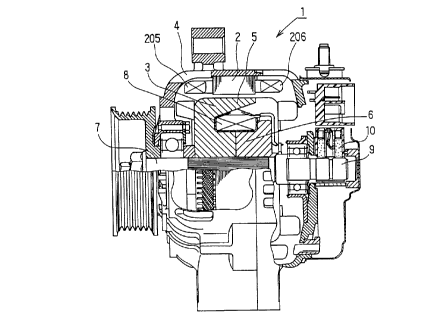
Fig. 1 is a cross-sectional view of an alternator for
a vehicle according to a first embodiment of the present
invention;
10Fig. 2 is a fragmentary perspective view illustrating
U-turn portions of a winding;
Fig. 3 is a cross-sectional view illustrating the
stator shown in Fig. l;
Fig. 4 is a graph showing a distribution of hardness of
15the U-turn portions of the winding of the first embodiment in
the axial direction;
Fig. 5 is a graph showing a difference in the resonant
characteristics between the stator according to the first
embodiment and a conventional stator;
20Fig. 6 is a graph showing comparing the magnetic noise
of the stator core according to the first embodiment with that
of a conventional stator;
Fig. 7 is a perspective view of an axial end of the
stator according to a second embodiment of the present
25invention;
Fig. 8 is a perspective view of the other end of the
stator according to the second embodiment;
CA 02238600 1998-06-18
Fig. 9 is a perspective view of a conductor segment of
the stator according to the second embodiment; and
Fig. 10 is a perspective view of a conductor segment
according to another embodiment of the present invention.
DETAILED DESCRIPTION OF PREFERRED EMBODIMENTS
[First Embodiment]
A 100-ampere-class alternator for a vehicle according
to a first embodiment of the invention is described with
reference to the drawings.
In Fig. 1, alternator 1 is composed of stator 2 as an
armature, rotor 3 as a magnetic field and frame 4 for
supporting stator 2 and rotor 3. Frame 4 contains therein a
regulator and a rectifier for converting ac power to dc power,
which are not shown.
Rotor 3 is composed of pole core 6 having twelve claw
poles 5 and shaft 7 which is press-fitted into pole core 6 via
serrated surface thereof. The left end of shaft 7 in Fig. 1
carries a pulley for inputting driving power. The center boss
portion of pole core 6 has a field coil wound therearound.
Field coil 8 is connected to the regulator through slip rings
9 and brushes 10. Rotor provides N and S poles alternately from
claw poles.
Stator 2 has stator core 201 provided with 36 slots
202. Stator core 201 is composed of laminated electric steel
sheets having thickness of 0.5 mm. The axial thickness of
stator core 201 is about 30 mm and outside diameter thereof is
CA 02238600 1998-06-18
about 120 mm.
A portion of continuous copper wire 20 is inserted each
one of slots 202 to form a multi-phase stator winding. As shown
in Fig. 2, copper wire 20 has U-turn portions extending axially
from different slots 202. Electric insulating members 204 are
disposed between copper wire 20 and the walls of slots 202.
Copper wire 20 is inserted into each slot 202 to hold insulator
204 and is fixed therein by adhesive agent 207. Copper wire 20
has a rectangular cross-section and is coated with resinous
insulation material.
Copper wire 20 is processed to have the area of the
rectangular cross-section of about 2 mm2 all over the length
and also to increase the hardness thereof.
A plurality of U-turn portions or coil ends 205, 206
are disposed U-turn portions 205, 206 are disposed annularly
along the circumferences on the opposite axial ends of stator
core 201. U-turn portions 205 on the pulley-side are heated and
softened above the edge of U-turn portions 205 through the
insulation coating or after removing the insulation coating, as
shown in Fig. 2.
As a result, the hardness of the hardened portions
after the above shaping process are reduced, and so that
different portions of wire 20 can have different hardness as
shown in Fig. 4. Thus, the edge of U-turn portions 205 become
softer than others, and portions closer to the slots becomes
harder. In other words, U-turn portions 205 on the pulley-side
become softer at portions closer to the edge and harder at
CA 02238600 1998-06-18
portions closer to the slots. Further, U-turn portions 205 of
the pulley-side are softer than the other U-turn portions 206.
As a result, stator 2 has low vibration-stiffness on
the pulley-side thereof and high vibration-stiffness on the
5opposite side, thereby providing a difference in the vibration
phase therebetween. This moderates and reduces the amplitude of
the vibration and reduces the magnetic noise.
Because hardness of the U-turn portions are changed,
the transmission of the vibration from stator core 201 to U-
10turn portions is suppressed so that the magnetic noise, which
is generated due to vibration of U-turn portions, can be
suppressed.
Since copper wire is heated after it is processed for
shaping, the difference in the hardness can be made bigger than
15the round wire. This is effective for the reduction of the
vibration and magnetic noise.
The above described shaping process and heating-and-
softening process are very simple and can dispense with special
and expensive processes for changing composition of a wire
20material along the axis of the stator. Moreover, the heating-
and-softening process can be carried out very simply above the
edge of U-turn portions 205.
The shaping process of copper wire 20 can be carried
out very easily, and the hardness of copper wire 20 can be
25changed as desired.
Copper wire 20 can be formed from a flat wire on the
market if it has a desirable hardness after the shaping process
CA 02238600 1998-06-18
and is not annealed to be softened.
The effect of the above structure is shown in Fig. 5.
ratios of resonance amplitude are compared between the stator
of the alternator according to the first embodiment and a
stator of a conventional 100-ampere-type alternator under the
same vibration amplitude. It was found that the ratio of the
stator according to the first embodiment was less than 1/6 of
the ratio of the conventional stator.
Fig. 6 shows distribution of the magnetic noises over
the number of revolutions per minutes. It is clear that the
magnetic noise generated by the alternator according to the
first embodiment of the present invention is smaller than a
conventional alternator. In general, the magnetic noise
generated in the engine speed range from the idling speed to
1500 rpm, which corresponds to the speed range of the
alternator from 1000 to 4000 with the pulley ratio being 2.5,
is particularly harsh. However, the magnetic noise in this
speed range is 5-7 dB less than the noise of the conventional
alternator. The alternators according to the first embodiment
of types other than 200-ampere-type have the same effect.
[Second Embodiment]
A stator core according to a second embodiment of the
present invention is described with reference to Figs. 7-9. A
stator winding is composed of a plurality of conductor segments
203 connected one another as shown in Fig. 9.
Conductor segments 203 are formed by shaping round
wires into flat segments. The shaping process hardens conductor
CA 02238600 1998-06-18
segments 203. The shape of conductor segments 203 corresponds
to the shape of the cross-section of the slots. Conductor
segments 203 are inserted into the slots and connected to form
a winding having a high occupation ratio of conductors.
Each of conductor segments 203 has two straight
conductor members 203 A and a U-turn portion 203B. As shown in
Figs. 7 and 8, straight conductor members 203A of conductor
segments 203 are aligned in slot 202 in the radial direction.
U-turn portion 203B are disposed on an axial end of stator core
201. Straight conductor members 203A extending from the other
axial end of stator core 201 are bent and connected to ends of
other segments 203 as shown in Fig. 7 to form the stator
winding as a whole.
In Fig. 7, conductor members 2031, 2032 of conductor
segments 203 are welded at edge portion 2051. This welding also
softens the conductor members. Thus, the welding at edge
portions 2052, 2053 and others connect and soften the conductor
members of all the conductor segments 203 very easily.
As shown in Fig. 7, a half of straight conductor
members 203A extends from the outer layer of slots 202 in one
circumferential direction and the other half conductor members
203A extend from the inner layer of slots 202 in the other
circumferential direction so that those conductor members 203A,
203B can be welded at the ends thereof. Accordingly, all the
coil ends are spaced apart from one another in the
circumferential and radial directions.
As shown in Fig. 8, the coil ends having U-turn
CA 02238600 1998-06-18
portions 203B extend from slot 202 and are spaced apart from
one another.
In the second embodiment, all segments 203 are
connected and softened only by the welding to have different
hardnesses, thereby reducing vibration effectively
As stated the coil ends are disposed on an axial end of
stator core 201 to be heated and softened by welding and other
coil ends having U-turn portion are disposed on the other end
of stator core 201 with the hardness unchanged, so that
difference in the hardness in the axial direction can be
provided to reduce the vibration effectively.
As shown in Fig. 9, U-turn portions 203B of conductor
segments 203 once hardened by the shaping process are further
hardened when the U-turn shape is formed by the bending
process, and the vibration can be further reduced. If stator
core 201 and the stator winding are deemed a cylindrical
member, portions having the same hardness are disposed on the
same circumferential plane, and axially different portions have
different hardnesses, thereby providing a high vibration
reduction effect. As shown in Fig. 7, welded portions 2051,
2052, 2053 and others can be easily inspected to know the
result of heating-and-softening process.
[Other embodiments]
The coil ends on the side opposite the pulley can be
heated instead of the coil ends on the pulley side according to
the first embodiment.
In the first and second embodimentsj the edge or end
CA 02238600 1998-06-18
portions can be heated at a comparatively low temperature to
prevent damage of the coating of conductor segments 203 by
cooling the coil ends on the other side of stator core.
Conductor segments 213 shown in Fig. 10 can be also
used. Each of conductor segments 213 has a straight conductor
member 213A, which is inserted into a slot in an axial
direction from one end and is bent to cover a certain pitch at
the other end thereof. Then each conductor member 213 is heated
and connected by a welder to form a winding
The distribution of different hardnesses can be changed
from that shown in Fig. 4. For example, it is also possible
that the hardness of points b, c are not lowered as shown in
Fig. 4 and only point a is softened as shown in Fig. 4.
In the foregoing description of the present invention,
the invention has been disclosed with reference to specific
embodiments thereof. It will, however, be evident that various
modifications and changes may be made to the specific
embodiments of the present invention without departing from the
broader spirit and scope of the invention as set forth in the
appended claims. Accordingly, the description of the present
invention in this document is to be regarded in an
illustrative, rather than restrictive, sense.