Note: Descriptions are shown in the official language in which they were submitted.
CA ~2238728 l998-~s-27
Method and device for milling three-~;m~ional workpieces
Description
The invention is related to a method for milling three-
dimensional workpieces, in which a geometric description of the
workpiece, preferably in the form of 3D CAD data, is numerical-
ly broken down into 2D or 3D data of a plurality of layers of
equal or differing thickness and, starting therefrom, is trans-
formed into NC milling programs which are to be executed layer-
by-layer. For the production of the workpiece plate-shaped
blanks having a predetermined wall thickness are machined ac-
cording to the NC-milling programm applicable to the correspon-
ding layer and are joined to each other at their facing broad
side surfaces, for instance by means of an adhesive. In this
manner it is possible to produce and assemble layer-by-layer
complex three-dimensional workpieces by means of comparatively
simple automated production steps. When using this method,
though, it is necessary to very carefully assemble the machined
blanks in order to achieve precisely fitting joints between the
blanks without protruding excess adhesive. Furthermore, dif-
ficulties concerning chip removal may arise especially for deep
and narrow contours in the workpiece.
Based on this it is the object of the invention to develop a
method and a device of the type described above, with which the
joining operation is simplified and the chip removal during the
machining is improved.
For the solution of this object the combinations of features of
patent claims l and 15 are suggested. Advantageous embodiments,
further developments and preferred applications result from the
dependent claims.
The solution according to the invention is based on the idea
~hat plate-shaped blanks having a predetermined, optionally va-
riable, wall thickness are joined successively in a laminar
CA 02238728 1998-0~-27
manner to a base structure or a previously machined blank and
machined according to the NC-milling programm applicable to the
corresponding layer at their lower exposed broad side from be-
low with upwardly directed milling tools.
The method according to the invention is suited especially for
producing workpieces having a preferred orientaion, for instan-
ce casting moulds or erosion electrodes, in the contours of
which the direction of removal from the mould defines the pre-
ferred orientation. The laminar technique according to the in-
vention makes possible a standardized choise of tools, since it
is always relatively thin, similar layers which have to be ma-
chined. The milling data can be optimized for a given material.
In particular, always the same milling parameters, such as feed
speed and offset step, result for a given layer thickness and
equal material. The overhead milling according to the invention
ensures a good removal of chips and material. This advantage
becomes apparent especially for deep contours, in which other=
wise surplus material and chips could collect, which are dif-
ficult to remove. Furthermore, the overhead milling ensuresthat adhesive protruding from a joint flows in the direction o~
the last added, not yet machined blank and is removed together
with the chips during the following machining operation. The
coolant and lubricant fed to the place of machining by way of
the milling tool may also easily flow downward during overhead
milling, carrying along the chips.
Accordi~g to a preferred embodiment of the invention it is pro-
vided that the plate-shaped blanks are taken from a stack of
blanks or pulled of a supply roll and cut to length. The not-
yet-machined blanks are then glued, welded or soldered with
their upwardly oriented broad side surface to the downwardly
oriented broad side sur~ace of the previously machined blank.
In order to save adhesive, the not-yet-machined blanks are only
partially covered with glue at the points of contact with the
previously machined blank.
CA 02238728 1998-0~-27
In order to ensure an exact alignment of the plane surface for
the following lamination and a high degree of dimensional pre-
cision, it is of advantage when the blanks which are added last
are plane-milled before or after the contour machining under
settlng of a defined thickness measure.
The transformation of the geometric data into the NC programs
for the individual layers is performed taking into considerati-
on a predetermined milling strategy. In this, especially theline offset during the milling operation has to be preset,
which determines the precision and the surface quality of the
workpiece. In the interest of a smooth transition at the joint
between two layers it is of advantage when the first lines are
not fully milled but milled away together with the adhesive
when machining the following layer. In this case the region of
the joint between two blanks is therefore machined in an over-
lapping manner. The line offset can also be chosen to be varia-
ble, especially in the instance of slanted contours, in order
to achieve a defined surface roughness. In this case the NC
program automatically determines additional intermediate steps
which ensure that the line offset is matched to the variable
angle of attack.
For graphite workpieces which are mainly used as electrodes for
the cavity-sinking erosion technique it is important that the
workpieces are continuously electracally conducting. In this
instance an electrically conductive adhesive is expediently
used. Furthermore, scavenging bores are needed in this case,
which facilitate the removal of material and at the same time
serve a cooling function. These scavenging bores can be created
by the milling process in that portions which are overlapped by
higher layers are removed in deeper layers. The milling chan-
nels can be led to the outside by means o~ sink bores.
In order to lncrease the conductivity between the individual
layers it can be necessary to provide openings created by the
~ CA 02238728 1998-0~-27
milling process, which may be fitted with conductive pins after
completion of the workpiece.
An especially advantageous device for implementing the method
according to the invention has at least one milling head for
accepting milling tools, a workpiece holder, and a multiple
axis CNC control for the relative movement of the milling head
with respect to the workpiece holder, wherein the workpiece
holder is disposed above the milling head and is adapted to be
supplied ~rom below with plate-shaped blanks, one after the
other, which blanks are adapted to be joined to each other at
their broad side surfaces and which blanks are machined from
below layer-by-layer with the aid of the CNC-control. Further,
the device advantageously comprises a storage space for blanks
which is preferably formed to be a plate stack or supply roll,
a device for applying an adhesive to at least one broad side
surface of the blanks to be joined to each other, and a manipu-
lating device ~or the blanks to be joined to each other.
The method according to the invention is suited in particular
for manufacturing casting moulds made of metal, ceramic materi-
al or synthetic material, for manufacturing cavity-sinking ero-
sion electrodes made of graphite, and for manufacturing models
or protDtypes made of metal, ceramic material, synthetic mate-
rial or wood.
In the following the invention is further described with refe-
rence to the accompanying drawing, in which:
~0 Fig. la and b show a schematic graphic representation of a
workpiece geometry with two examples of a layer divi-
sion, having a constant and a variable layer thick-
nessi
~5 Fig. 2 schematically shows a feeding device in a milling
station for manufacturing three-dimensional work-
pleces i
~ CA 02238728 1998-0~-27
s
Fig. 3a to c show three typical stages of the milling
process;
~ Fig. 4a to f show a schematic representation of a series of
intermediate steps when machining a workpiece accor-
ding to Fig. lb.
The method described hereafter with reference to the drawing is
intended for milling complex three-dimensional workpieces, for
instance casting moulds or erosion electrodes. The geometry of
the workpiece 1 is ~irst measured as 3D CAD data with the aid
of a suitable computer software. These geometries are usually
geometries which are not suited to be milled from stock due to
the complexness and deeply undercut contours. The manufacturing
is therefore performed by means of the layer process, in which
the workpiece 1 is successively assembled from plate-shaped ma-
terial layers 10, 12, 14, 16, 18, 20 having equal (Fig. la) or
variable (Fig. lb) layer thicknesses. The layer thickness is
chosen such that in each layer a sufficient amount of material
is present for the milling operation at the places to be ma-
chined. In the instance of equal layer thicknesses as in Fig.
la, this is not the case at points 22 and 24, which is why in
this example the configuration of Fig. lb, in which the thick-
ness of layer 16 is less than that of the other layers, is pre-
ferred. Moreover, in the configuration shown in Fig. lb support
areas 30 are provided outside the outer edge 26 of the work-
piece, which areas are separated from the outer edge 26 by a
gap 28 and which ensure an exact positioning of the joining
planes 32 between the layers at all stages of the process.
After determining the layers 10 to 20 the 3D CAD data-set of
the workpiece geometry is broken down into 2D or 3D data of in-
dividual layers 10 to 20 by means of a software routine. With
the additional predetermination of the milling strategy (in
particular the choice of milling tool for pre-milling and ~ine
milling, fee~ speed, and line offset), the NC programs to be
-
~ . CA 02238728 1998-0~-27
performed layer-by-layer can be created from the layer-speciflc
contour data thus obtained.
The actual application of the milling programs to the workpiece
takes place in a CNC milling machine 34 which comprises a mil-
ling head which is adapted to accept milling tools 36, 38, 40,
a blank supply magazine 44 which is filled with plate-shaped
blanks 42, a device 46 for applying an adhesive, and a handling
facility for the blanks 42, which has a displacement member 48
and a pressure member 50.
For the production of the workpiece 1 the top broad side sur-
face 52 o~ the uppermost blank 42 is coated with adhesive with
the aid of the coating device 46, and is then glued to a base
plate 54, which is disposed on a tool holder (not shown), as
layer 10 by means of the displacement member 48 and the pressu-
re member 50. Thereafter, the NC milling program allocated to
layer 10 is performed, and the contours 56, 58 which are shown
in Fig. 4a are milled into the layer 10 from the broad side 60.
When the contour-milling of the first layer 10 is finished, a
further blank 42 is taken from the magazine 44 and joined to
the free broad side surface 60 of the layer 10 with its adhesi-
ve-coated broad side surface 52 (Fig. 4b). This blank is milled
from the free broad side surface 60 according to the NC program
allocated to layer 12, forming the contours 56, 58. This
process is repeated for the layers 14, 16, 18, and 20 (Fig. 4c
to f), until the workpiece 1 is completed.
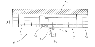
As can be seen from Fig. 3a and b for the milling step of Fig.
4d, the milling is performed overhead with upwardly oriented
end-milling cutters 36, 38, wherein the milling tool 36 is used
for pre-milling and the milling tool 38 is used for fine mil-
ling. The surplus pieces 62 and chips 64 created during the
milling process fall downward according to gravity. Chip remo-
val is further aided by coolant and lubricant sprayed upward
through the milling head in the direction of the workpiece 1
and de~lected downward at the workpiece. As can be seen espe-
~ CA 02238728 1998-0~-27
cially in Fig. 3b, the contour machining is performed in steps
along progressing milling paths from bottom to top, for example
in steps of 0.5 mm, wherei~ the final milling path crosses into
the previously machined layer 14, overlapping the plane 32 of
the joint, and ensures that a smooth, adhesive-free transition
between the layers 14, 16 results.
In order to avoid incremental errors during the layer build-up,
the free broad side surface 60 is machined to a predefined di-
stance value using a plane milling tool 40 before or after eachcontour machining step. The support areas 30 at the outer edges
ensure that the following blank 42 is aligned precisely in the
joint plane 32 and can be ~oined to the previously machined
blank. After completion of the workpiece 1 the portions forming
the support areas 30 are removed from the base plate 54, and
the workpiece is put to its use after optional finishing and
tempering.
In summary the following is to be stated: The invention is re-
lated to a method for milling three-dimensional workpieces,
especially for manufacturing casting moulds and erosion
electrodes. According to the method a geometric description o~
the workpiece 1, preferably in the form o~ 3D CAD data, is nu-
merically broken down into 2D or 3D data of a plurality of
layers 10 to 20 of equal or dif~ering thickness and, starting
there~rom, is transformed into NC milling programs which are to
be executed layer-by-layer. For the production o~ the workpiece
1 plate-shaped blanks 42 having a predetermined, optionally va-
riable, wall thickness are ~oined successively in a laminar
manner to a base structure 54 or a previously machined blank 42
and machined according to the NC-milling programm applicable to
the corresponding layer 10 to 20 at their lower exposed broad
side 6Q ~rom below with upwardly directed milling tools 36, 38,
40.