Language selection

Search

Patent 2238947 Summary

Third-party information liability

Some of the information on this Web page has been provided by external sources. The Government of Canada is not responsible for the accuracy, reliability or currency of the information supplied by external sources. Users wishing to rely upon this information should consult directly with the source of the information. Content provided by external sources is not subject to official languages, privacy and accessibility requirements.

Claims and Abstract availability

Any discrepancies in the text and image of the Claims and Abstract are due to differing posting times. Text of the Claims and Abstract are posted:

  • At the time the application is open to public inspection;
  • At the time of issue of the patent (grant).
(12) Patent Application: (11) CA 2238947
(54) English Title: TOILET PAPER DISPENSER
(54) French Title: PORTE-PAPIER HYGIENIQUE
Status: Deemed Abandoned and Beyond the Period of Reinstatement - Pending Response to Notice of Disregarded Communication
Bibliographic Data
(51) International Patent Classification (IPC):
  • A47K 10/34 (2006.01)
  • A47K 10/32 (2006.01)
  • A47K 10/38 (2006.01)
(72) Inventors :
  • MICKLICH, BRIAN MICHAEL (Canada)
(73) Owners :
  • BRIAN MICHAEL MICKLICH
(71) Applicants :
  • BRIAN MICHAEL MICKLICH (Canada)
(74) Agent: DOUGLAS B. THOMPSONTHOMPSON, DOUGLAS B.
(74) Associate agent:
(45) Issued:
(22) Filed Date: 1998-05-26
(41) Open to Public Inspection: 1999-11-26
Examination requested: 1999-01-15
Availability of licence: N/A
Dedicated to the Public: N/A
(25) Language of filing: English

Patent Cooperation Treaty (PCT): No

(30) Application Priority Data: None

Abstracts

English Abstract


A toilet paper dispenser which includes a housing having
a first housing portion pivotally connected to a second housing
portion. At least one gripping pad is positioned on one of the
first housing portion and the second housing portion. A toilet
paper roll is mounted within the housing with a free end of the
toilet paper roll extending from the housing. By selectively
causing relative pivotal movement of the first housing portion
and the second housing portion, the gripping pad is caused to
grip either the toilet paper roll or toilet paper extending
from the toilet paper roll so that the free end of the toilet
paper roll may be detached.


Claims

Note: Claims are shown in the official language in which they were submitted.

6
THE EMBODIMENTS OF THE INVENTION IN WHICH AN EXCLUSIVE PROPERTY
OR PRIVILEGE IS CLAIMED ARE DEFINED AS FOLLOWS:
1. A toilet paper dispenser, including:
a housing having a first housing portion and a second
housing portion that define an interior cavity, the first
portion being pivotally connected to the second portion for
pivotal movement about a substantially horizontal axis, each
of the first housing portion and the second housing portion
having a pivotally connected end and a remote end;
at least one gripping means on at least one of the first
housing portion and the second housing portion;
means for rotatably mounting a toilet paper roll within
the interior cavity of the housing with a free end of the
toilet paper roll extending from the housing; and
means for selectively causing relative pivotal movement
of the first housing portion and the second housing portion to
bring the at least one gripping means into engagement with one
of the toilet paper roll and toilet paper extending from the
toilet paper roll when a desired quantity of toilet paper has
been fed from the toilet paper roll so that the free end of the
toilet paper roll may be detached.
2. The toilet paper dispenser as defined in Claim 1, wherein
there is first gripping means at the remote end of the first
housing portion and second gripping means at the remote end of
the second housing portion.
3. The toilet paper dispenser as defined in Claim 1, wherein
means is provided for maintaining the at least one gripping
means spaced from the toilet paper roll and the toilet paper
extending from the toilet paper roll.
4. The toilet paper dispenser as defined in Claim 2, wherein
the means for maintaining the at least one gripping means in
spaced relation is a spring biased member.

7
5. The toilet paper dispenser as defined in Claim 1, wherein
the at least one gripping means is in the form of a gripping
pad.

8
6. A toilet paper dispenser, including:
a housing having a first housing portion and a second
housing portion that define an interior cavity, the first
portion being pivotally connected to the second portion for
pivotal movement about a substantially horizontal axis, each
of the first housing portion and the second housing portion
having a pivotally connected end and a remote end;
a first gripping pad at a remote end of the first housing
portion;
a second gripping pad at a remote end of the second
housing portion;
a pin mounted on one of the first housing portion and the
second housing portion and engaging the other of the first
housing portion and the second housing portion to maintain the
first gripping pad and the second gripping pad in spaced
relation, the pin being moveable between a retracted position
and an extended position, a biasing spring maintaining the pin
in a normally extended position;
a pair of spaced apart brackets for rotatably mounting a
toilet paper roll on a cylindrical support within the interior
cavity of the housing with a free end of the toilet paper roll
extending from the housing and a mid-portion of toilet paper
extending from the toilet paper roll positioned between the
first gripping pad and the second gripping pad; and
a handle for selectively causing relative pivotal of the
first housing portion relative to the second housing portion
to bring the first gripping pad and the second gripping pad
together to grip the mid-portion of the toilet paper extending
from the toilet paper roll when a desired quantity of toilet
paper has been fed from the toilet paper roll so that the free
end of the toilet paper roll may be detached.

Description

Note: Descriptions are shown in the official language in which they were submitted.


CA 02238947 1998-OS-26
1
TITLE OF THE INVENTION:
toilet paper dispenser
NAME ( S ) OF INVENTOR ( S )
Brian Michael Micklich
FIELD OF THE INVENTION
The present invention relates to a toilet paper dispenser
and, in particular, a toilet paper roll dispenser that has a
cover which either totally or partially conceals a toilet paper
roll from which toilet paper is dispensed.
BACKGROUND OF THE INVENTION
There are numerous toilet paper dispensers that have
covers which either totally or partially conceal a toilet paper
roll from which toilet paper is dispensed. While the presence
of a cover improves the aesthetic appearance of the toilet
area, it also makes it more difficult for the user to control
the quantity of toilet paper being dispensed. For this reason,
toilet paper dispensers that have covers tend to have complex
mechanisms to perform the task of regulating the quantity of
toilet paper dispensed.
An example of such a toilet paper dispenser is United
States Patent 4,089,481 which issued to Cluci in 1978. The
Cluci reference discloses a covered toilet paper dispenser
having a slot through which the toilet paper protrudes . A pair
of rollers are positioned in close relation of either side of
the slot. One roller is an idler roller, the other roller has
a knob and is a drive roller which is used to feed toilet paper
from the toilet paper roll.
SUMMARY OF THE INVENTION
What is required is a less complex form of covered toilet
paper dispenser.
According to the present invention there is provided a

CA 02238947 1998-OS-26
2
toilet paper dispenser which includes a housing having a first
housing portion and a second housing portion that define an
interior cavity. The first portion is pivotally connected to
the second portion for pivotal movement about a substantially
horizontal axis. Each of the first housing portion and the
second housing portion have a pivotally connected end and a
remote end. At least one gripping means on at least one of the
first housing portion and the second housing portion. Means
are provided for rotatably mounting a toilet paper roll within
the interior cavity of the housing with a free end of the
toilet paper roll extending from the housing. Means are
provided for selectively causing relative pivotal movement of
the first housing portion and the second housing portion to
bring the at least one gripping means into engagement with one
of the toilet paper roll and toilet paper extending from the
toilet paper roll when a desired quantity of toilet paper has
been fed from the toilet paper roll so that the free end of the
toilet paper roll may be detached.
The toilet paper dispenser, as described above, has a
simple and yet effective means for temporarily exerting
pressure upon either the toilet paper roll or the toilet paper
extending from the toilet paper roll. The pressure exerted
prevents further toilet paper from being dispensed from the
roll as a force is exerted to detach the free end of the toilet
paper roll which extends from the housing. There are a variety
of gripping means which could be provided. Beneficial results
have been obtained through the use of a first gripping pad at
the remote end of the first housing portion and a second
gripping pad at the remote end of the second housing portion.
Although beneficial results may be obtained through the
use of the toilet paper dispenser, as described above, should
the first gripping pad and the second gripping pad prematurely
come together, the dispensing of toilet paper from the toilet
paper roll would be impeded. Even more beneficial results may,
therefore be obtained when means is provided for maintaining

CA 02238947 1998-OS-26
3
the first gripping means and the second gripping means in
spaced relation. One form of means that can be used is a
spring biased member, such as a pin.
BRIEF DESCRIPTION OF THE DRAWINGS
These and other features of the invention will become more
apparent from the following description in which reference is
made to the appended drawings, wherein:
FIGURE 1 is a perspective view of a toilet paper dispenser
constructed in accordance with the teachings of the present
invention.
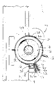
FIGURE 2 is a side elevation view, in section, of the
toilet paper dispenser illustrated in FIGURE 1, with first
housing portion pivoted relative to second housing portion to
allow for insertion of a toilet paper roll.
FIGURE 3 is a side elevation view, in section, of the
toilet paper dispenser illustrated in FIGURE 1, with the first
gripping pad and the second gripping pad in spaced relation.
FIGURE 4 is a side elevation view, in section, of the
toilet paper dispenser illustrated in FIGURE 1, with the first
gripping pad and the second gripping pad engaged.
FIGURE 5 is a front elevation view of the toilet paper
dispenser illustrated in FIGURE 1.
DETAILED DESCRIPTION OF THE PREFERRED EMBODIMENT
The preferred embodiment, a toilet paper dispenser
generally identified by reference numeral 10, will now be
described with reference to FIGURES 1 through 5.
Referring to FIGURE 1, toilet paper dispenser 10 includes
a housing 12. Referring to FIGURE 2, housing 12 includes a
first housing portion 14 and a second housing portion 16 that
define an interior cavity 18. Second housing portion 16 is
adapted to be secured within an opening 17 in an interior wall
19 by means of screws 21. Second housing portion 16 has
shoulders 23 which limit the penetration of second housing

CA 02238947 1998-OS-26
4
portion 16 into opening 17. First housing portion 14 is
pivotally connected by hinge 20 to second housing portion 16
for pivotal movement about a substantially horizontal axis
defined by hinge pin 22. First housing portion 14 has a
pivotally connected end 24 and a remote end 26. Second housing
portion 16 has a pivotally connected end 28 and a remote end
30. A first gripping pad 32 is positioned at remote end 26 of
first housing portion 14. A second gripping pad 34 is
positioned at remote end 30 of second housing portion 16.
Referring to FIGURE 5, a pair of pins 36 are mounted on second
housing portion 16 on either side of second gripping pad 34.
Referring to FIGURE 3, pins 36 engage first housing portion 14
to maintain first gripping pad 32 and second gripping pad 34
in spaced relation. Pins 36 are moveable between a retracted
position illustrated in FIGURE 4 and an extended position
illustrated in FIGURE 3. Referring to FIGURES 2 and 3, biasing
springs 38 maintain pins 36 in a normally extended position.
Referring to FIGURE 5, a pair of spaced apart brackets 40 are
positioned within interior cavity 18 of second housing portion
16. Referring to FIGURE 2, brackets 40 are used for rotatably
mounting a toilet paper roll 42 within interior cavity 18 of
housing 12. Referring to FIGURE 3, a free end 44 of toilet
paper roll 42 is extended from housing 12. A mid-portion 46
of toilet paper extending from toilet paper roll 42 is
positioned between first gripping pad 32 and second gripping
pad 34. A handle 48 is attached to first housing portion 14.
The use and operation of toilet paper dispenser 10 will
now be described with reference to FIGURES 1 through 5.
Referring to FIGURE 2, a toilet paper roll 42 is positioned on
a cylindrical support 49 and positioned within interior cavity
18 of housing 12 with cylindrical support 49 held by brackets
40. Referring to FIGURE 3, free end 44 of toilet paper roll
42 is extended from housing 12 with a mid-portion 46 of toilet
paper extending from toilet paper roll 42 positioned between
first gripping pad 32 and second gripping pad 34. Pins 36
positioned on either side of second gripping pad 34, maintain

CA 02238947 1998-OS-26
first housing portion 14 spaced from second housing portion 16.
Referring to FIGURE 4, a person using toilet paper dispenser
grips with a first hand 50 free end 44 of toilet paper roll
42 which extends from housing 12 and pulls upon free end 44 to
5 dispense a desired quantity of toilet paper from housing 12.
When a desired quantity of toilet paper has been dispensed, the
person takes a second hand 52 and exerts pressure upon handle
48 to cause pivotal movement of first housing portion 14
relative to second housing portion 16. This brings first
10 gripping pad 32 and second gripping pad 34 together to grip
mid-portion 46 of the toilet paper extending from toilet paper
roll 42. The desired quantity of toilet paper from free end
44 that has been fed from toilet paper roll 42 is then readily
detached by exerting a shearing force with first hand 50.
It will be apparent to one skilled in the art that
modifications may be made to the illustrated embodiment without
departing from the spirit and scope of the invention as
hereinafter defined in the Claims. One modification that may
be made is to use just gripping pad on first housing portion
14 and have that gripping pad act directly against toilet paper
roll 42.

Representative Drawing
A single figure which represents the drawing illustrating the invention.
Administrative Status

2024-08-01:As part of the Next Generation Patents (NGP) transition, the Canadian Patents Database (CPD) now contains a more detailed Event History, which replicates the Event Log of our new back-office solution.

Please note that "Inactive:" events refers to events no longer in use in our new back-office solution.

For a clearer understanding of the status of the application/patent presented on this page, the site Disclaimer , as well as the definitions for Patent , Event History , Maintenance Fee  and Payment History  should be consulted.

Event History

Description Date
Inactive: IPC from MCD 2006-03-12
Application Not Reinstated by Deadline 2003-05-26
Time Limit for Reversal Expired 2003-05-26
Deemed Abandoned - Conditions for Grant Determined Not Compliant 2002-10-03
Deemed Abandoned - Failure to Respond to Maintenance Fee Notice 2002-05-27
Letter Sent 2002-04-03
Notice of Allowance is Issued 2002-04-03
Inactive: Approved for allowance (AFA) 2002-03-22
Amendment Received - Voluntary Amendment 2002-02-19
Inactive: S.30(2) Rules - Examiner requisition 2001-08-28
Inactive: Cover page published 1999-11-26
Application Published (Open to Public Inspection) 1999-11-26
Amendment Received - Voluntary Amendment 1999-03-16
Request for Examination Received 1999-01-15
Request for Examination Requirements Determined Compliant 1999-01-15
Letter Sent 1999-01-15
All Requirements for Examination Determined Compliant 1999-01-15
Inactive: First IPC assigned 1998-08-28
Classification Modified 1998-08-28
Inactive: IPC assigned 1998-08-28
Inactive: Filing certificate - No RFE (English) 1998-08-13
Filing Requirements Determined Compliant 1998-08-13
Application Received - Regular National 1998-08-07

Abandonment History

Abandonment Date Reason Reinstatement Date
2002-10-03
2002-05-27

Maintenance Fee

The last payment was received on 2001-03-14

Note : If the full payment has not been received on or before the date indicated, a further fee may be required which may be one of the following

  • the reinstatement fee;
  • the late payment fee; or
  • additional fee to reverse deemed expiry.

Please refer to the CIPO Patent Fees web page to see all current fee amounts.

Fee History

Fee Type Anniversary Year Due Date Paid Date
Application fee - small 1998-05-26
Request for examination - small 1999-01-15
MF (application, 2nd anniv.) - small 02 2000-05-26 2000-04-27
MF (application, 3rd anniv.) - small 03 2001-05-28 2001-03-14
Owners on Record

Note: Records showing the ownership history in alphabetical order.

Current Owners on Record
BRIAN MICHAEL MICKLICH
Past Owners on Record
None
Past Owners that do not appear in the "Owners on Record" listing will appear in other documentation within the application.
Documents

To view selected files, please enter reCAPTCHA code :


To view images, click a link in the Document Description column. To download the documents, select one or more checkboxes in the first column and then click the "Download Selected in PDF format (Zip Archive)" or the "Download Selected as Single PDF" button.

List of published and non-published patent-specific documents on the CPD .

If you have any difficulty accessing content, you can call the Client Service Centre at 1-866-997-1936 or send them an e-mail at CIPO Client Service Centre.


Document
Description 
Date
(yyyy-mm-dd) 
Number of pages   Size of Image (KB) 
Representative drawing 1999-11-05 1 16
Representative drawing 2002-03-22 1 14
Claims 1998-05-26 3 91
Description 1998-05-26 5 218
Abstract 1998-05-26 1 19
Drawings 1998-05-26 5 133
Cover Page 1999-11-05 1 39
Filing Certificate (English) 1998-08-13 1 174
Acknowledgement of Request for Examination 1999-02-18 1 177
Reminder of maintenance fee due 2000-01-27 1 113
Commissioner's Notice - Application Found Allowable 2002-04-03 1 166
Courtesy - Abandonment Letter (Maintenance Fee) 2002-06-25 1 183
Courtesy - Abandonment Letter (NOA) 2002-12-12 1 166