Note: Descriptions are shown in the official language in which they were submitted.
CA 02239086 1998-OS-28
WO 97!20298 PCT/CTS96119310
- 1 -
DIGITAL ANTI-COUNTERFEITING SOFTWARE METHOD AND APPARATUS
FIELD OF THE INVENTION
This invention relates generally to a method and apparatus,
as implemented by a software program on a computer system, for
' producing counterfeit-deterring scrambled or coded indicia
images, typically in a printed form. This method and system are
capable of combining a source image with a latent image so the
latent image is visible only when viewed through a special
decoder lens.
HACF~G~tOUND INFORMATION
To prevent unauthorized duplication or alteration of
_0 documents, frequently there is special indicia or a background
pattern provided for sheet materials such as tickets, checks,
currency, and the like. The indicia or background pattern is
imposed upon the sheet material usually by some type of printing
process such as offset printing, lithography, letterpress or
.5 other like mechanical systems, by a variety of photographic
methods, by xeroprinting, and a host of other methods. The
pattern or indicia may be produced with ordinary inks, from
special inks which may be magnetic, fluorescent, or the like,
from powders which may be baked on, from light sensitive
'0 materials such as silver salts or azo dyes, and the like. Most
of these patterns placed on sheet materials depend upon
complexity and resolution to avoid ready duplication.
Consequently, they add an increment of cost to the sheet
material without being fully effective in many instances in
'S providing the desired protection from unauthorized duplication
or alteration.
Various methods of counterfeit-deterrent strategies have
been suggested including Moire-inducing line structures,
variable-sized dot patterns, latent images, see-throughs, bar-
;0 codes, and diffraction based holograms. However, none of these
methods employs a true scrambled image or the added security
benefits deriving therefrom.
SUBSTITUTE SHEET (RULE 26)
CA 02239086 2002-05-09
- 2 -
This same inventor earlier disclosed a novel system for
coding and decoding indicia on printed matter by producing a
parallax panoramagram image. These principles and embodiments
of U.S. Patent No. 3,937,565, issued February 10, 1976 which
may be referred to for further details. The indicia were
preferably produced photographically using a lenticular line
screen (i.e. a lenticular screen) with a known spatial lens
density (e. g. 69 lines per inch). A specialized auto-
stereoscopic camera might be used to produce 'the parallax
image such as the one described in this inventor' s U . S . Patent
No. 3-,524,395, issued August 18, 1970, and U.S. Patent No.
3,769,890, issued November 6, 1973.
:. Photographic, or analog, production of coded indicia images '
has the drawback of requiring a specialized camera. Also, the .~ -
an.alog images are limited in their versatility in that an area ' :.
of scrambled indicia is generally noticeable when surrounded by
non-scrambled images. Also, it is difficult to combine several
latent images, with potentially different scrambling parameters,
due to the inability to effectively re-expose film segments in
generating the scrambled, photographic image.
Accordingly, a method and apparatus are needed whereby the
photographic process and its results are essentially simulated
digitally via a computer system and related software. w
Additionally, a system is needed whereby scrambled latent images : ~ ~ =
can be integrated into a source image, or ind3.vidual color
components thereof, so that the source image is visible to the
unaided eye and the latent image is visible only upon decoding.
Also needed is the ability to incorporate multiple latent
images, representing different "phases", into the source image
for added security. . ...
~U~RY OF THE IIB'V'~N~~"QN.
The present invention provides a software method and ,.
apparatus for digitally scrambling and incorporating latent , ,y
images into a source image. The latent image -- in digitized
form -- can be scrambled for decoding by a variety of lenticular . -
lenses as selected by the user, with each lens having different
optical properties such as different line densities per inch,
CA 02239086 1998-OS-28
WO 97/20298 PCT/US96/i9310
- 3 -
and/or a different radius of curvature for the lenticulas.
Different degrees of scrambling might also be selected wherein
the latent image is divided up into a higher multiplicity of
lines or elements. For decoding purposes, the multiplicity of
'5 elements would be a function of the lens density.
The source image is then rasterized, or divided up into a
series of lines equal in number to the lines making up the
scrambled latent images. Generally, when hard copy images are
printed, the image is made up of a series of 'sprinters dots"
which vary in density according to the colors found in the
various component parts of the image. The software method and
apparatus of the present invention, takes the rasterized lines
of the source image and reforms them into the same general
pattern as the lines of the scrambled latent image. Hence,
where the source image is darker, the scrambled lines are formed
proportionately thicker; where the source image is lighter, the
scrambled lines are formed proportionately thinner. The
resulting combined image appears to the unaided eye.like the
original source image. However, since the component rasterized
lines are formed in the coded pattern of the scrambled latent
image, a decoder will reveal the underlying latent image. Due
to the high printing resolution needed for such complex
scrambled lines, attempts to copy the printed image by
electromechanical means, or otherwise, are most often
unsuccessful in reproducing the underlying latent image.
As a result of this digital approach, several different
latent images can be scrambled and combined into an overall
latent image, which can then be reformed into the rasterized
source image. This is achieved by dividing the rasterized lines
into the appropriate number of images (or phases) and
interlacing the phased images in each raster line element . Each
individual latent image might be oriented at any angle and
scrambled to a different degree, so long as the scrambling of
each image is a functional multiple of the known decoder
frequency. Alternatively, the grey scale source image might be
divided up into primary component printing colors (e. g. cyan,
SUBSTITUTE SHEET (RULE 26)
CA 02239086 1998-OS-28
WO 97/2~298 PCT/US96/19310
- 4 -
magenta, yellow, and black, or CMYK; red, green, blue, or RGB?.
Single color bitmap formats might also be used for certain
applications. A scrambled latent image, or a mufti-phased
image, could then be individually reformed into each component
color. Upon rejoining of the colors to form the final source
image, the decoder will reveal the different latent images
hidden in the different color segments.
The present invention also allows the option of flipping
each of the elements of the latent image after it 'has been
divided or scrambled into its elemental line parts . As has been
discovered by the inventor, this unique step produces relatively
sharper decoded images when each of the elements is flipped
about its axis by one-hundred and eighty (180) degrees. This
same effect was achieved by the process of U.S. Patent No.
3,937,565, and the cited stereographic cameras therein, through
the inherent flipping of an object when viewed past the focal
point of a lens. The flipped elemental lines are then reformed
into the rasterized source image. While enhancing the sharpness
of the latent image, the flipping of the elements has no
adverse, or even noticeable, effect on the appearance of the
final coded source image. Moreover, by combining two images
consisting of one image where the elements are flipped and
another where they are not flipped, the appearance of a spatial
separation of the two images will occur upon decoding.
As needed, the source image might simply consist of a solid
color tint or a textured background which would contain hidden
latent images when viewed through the proper decoder. Such
solid, tinted areas might frequently be found on checks,
currency, tickets, etc.
Other useful applications might include the latent encoding
of a person' s signature inside a source image consisting of that
person's photograph. Such a technique would make it virtually
impossible to produce fake ID' s or driver' s licenses through the
common technique of replacing an existing picture with a false
one. Other vital information besides the person's signature
SUBSTITUTE SHEET (RULE 26)
CA 02239086 2003-05-09
- 5 -
(e.g. height, weight, identification number, etc,) might also be
included in the latent image for encoding into the source image.
Still other useful applications might include, for example,
the following: credit cards, passports, photo-identification
cards, currency, special. event tickets, stocks and bond
certificates, bank and travelers checks, anti-counterfeiting
labels (e. g. for designer clothe:a, drugs, liquors, video tapes,
audio CD's, cosmetics, machine parts, <~nd pharmaceuticals), tax
and postage stamps, birth certificates, vehicle restoration
cards, land deed titles, and visas.
Thus, the present invention seeps to provide a counterfeit-
deterrent method and apparatus, as implemented by a software
program on a computer system, for producing scrambled or coded
indicia images, typically in a printed form. The coded image can
then be decoded and viewed through ~ special lens which is
matched to the software coding process parameters.
Further, the present invention seeks to provide a
counterfeit-deterrent method and apparatu:~, as implemented by a
software program on a computer system, wherein a source image is
rasterized, and the latent image :is broken up into corresponding
elemental lines, and the rasterized source image is reconstructed
according to the coded pattern of the scrambled image.
Yet further, the present a.nvention seeks to provide a
counterfeit-deterrent method and apparatus, as implemented by a
software program on a computer system, wherein the source image
is converted into a grey scale image for incorporation of a
latent scrambled image.
Still further, the present invention seeks to provide a
counterfeit-deterrent method and apparatus, as implemented by a
software program on a computer system, wherein the grey scale
source image is further separated out. into its component color
parts for possible incorporation of latent scrambled images into
each component color part, with the parts being rejoined to form
the final encoded source image.
CA 02239086 2003-05-09
A related aspect of the pz°esent. invention seeks to provide
a counterfeit-deterrent method and apparatus, as implemented by
a software program on a computer system, wherein th,e elemental
lines of the scrambled image may be rotated or flipped about
their axis as necessary, or as selected by the user.
Further still, the present invention seeks to provide a
counterfeit-deterrent method and ~pparatu:~, as implemented by a
software program on a cc3mputer system, wherein t:he "single
phased" the scrambled image consists of a first latent image
which has been sliced and scrambled as a function of a user
selected decoder density and scrambling factor.
Yet further, the present invention seeks to provide a
counterfeit-deterrent method and apparatus, as implemented by a
software program on a computer system, wherein the "two phased"
scrambled image is sliced as s. function of a user selected
decoder density, and each slice is halved into two sub-slices,
and the first and second latent images are alternately interlaced
in the sub-slices, with each latent image scrambled by a user
selected scrambling factor.
Still further the present inventian seeks to provide a
counterfeit-deterrent method and apparatus, as implemented by a
software program on a computer system, wherein the "three phased"
scrambled image is sliced as a function of a user selected
decoder density, and each slice is divided into three sub-slices,
and the first, second, and third :Y.atent images are alternatively
interlaced in the sub-slices, with ea~°h latent image scrambled
by a user selected scrambling fa~aor.
Yet further the present invention seeks to provide a
counterfeit-deterrent method and apparatus, as implemented by a
software program on a computer system, wherein an "indicia tint"
is produced which. is similar to a two phased SI, but with one
source file, and every second srb-slice of the input image is the
complimenter of the first sub-slice.
CA 02239086 2003-05-09
- 7 _
Further still, the present invention seeks to provide a
counterfeit-deterrent method and apparatus, as implemented by a
software program on a camguter system, wherein the source image
consists of a solid color or. ta.nt pattern with the scrambled
image incorporated therein, but the elemental lines are flipped
only where a letter or object occurs in underlying latent image.
Still further, the present invention seeks to provide a
counterfeit-deterrent method and apparatus, as implemented by a
software program on a camputer system, wherein the latent image
is encoded directly into a certain visible figure on the source
image, thus creating a "hidden image" effect.
Yet further, the present invention seeks to provide a
counterfeit-deterrent method and apparatus, as implemented by a
software program on a computer system, wherein a bitmap source
image is used (instead of a grey scale image) to create hidden
images behind single color source images ox sections of source
images.
Still further, the present invention seeks to provide a
counterfeit-deterrent method and apparatus, as implemented by a
software program on a computer system, wherein a zmultilevel, 3-
dimensional relief effect: x.s created by applying different
scrambling parameters to an image axed its background.
Another related aspect of the present invention is to
provide a counterfeit-deterrent method and apparatus, as
implemented by a software pragram on a computer system, wherein
"void tint" sections might be produced and the word "void," or
similar such words, would appear across documents if attempts are
made to photocopy them.
Yet another aspect of the present invention seeks to provide
for the possible use of the software program and computer system
to produce the equivalent of "wager marks"" on paper products.
CA 02239086 2003-05-09
Still another aspect of t:he present. invention is the
possible use of the software program anal computer system to
produce, or to aid in producing, hol.ograph:ic images through line
diffraction techniques.
Other aspects and advantages of this invention will become
apparent from the following description taken in conjunction with
the accompanying drawings wherein are set. forth, by way of
illustration and example, certain. embodiments of this invention.
The drawings constitute a part of this specification and include
exemplary embodiments of the present invention and illustrate
various objects and features thereof.
BRIEF DESCRIPTION OF TfiE DRAWINGS
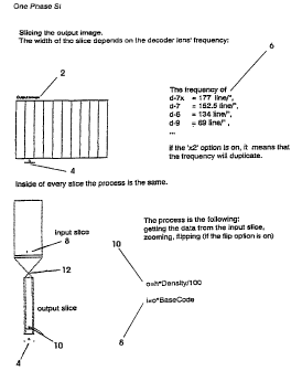
Figure 1 shows a "one ghase" example of the Scrambled
Indicia (SI) proc;ess wherein an output image is. sliced into
elements as a function of the frequency of the decoding lens and
the scrambling factor (or zoom factor, or base code) as selected
by the user.
Figure 2(a) shows a scrambled "P" (above) with its
resulting elements enlarged x:00% (below) wherein the elements
have been flipped 180 degrees about their vertical axes.
Figure ~(b) :ahOWS the scrambled "'P" (above) of Figure 9(a)
with its resulting elements enlarged ~t~0p i;below) wherein the
elements have not been flipped or alteredA.
Figure 3 shows a "two phase" S1 example of slicing the
output image, wherein the wxdt~a of the slice is one half of the
one phase example, with every odd slice being from a 'source
one' file, and every even slice being from a 'source two' file.
Figure 4 shows a "three phase" S1: example of slicing the
output image, wherein the width of the slice is one third of the
one phase example, with every third slice being from the same
source input file.
Figure 5 shows a comparison of the one, two, and three
phase scrambled and coded results.
CA 02239086 1998-OS-28
WO 97/20298 PCT/US96/19310
_ g _
Figure 6 shows a series comparison of scrambled images as
a function of increasing lens frequency (or line density per
inch) from 10 through 200.
Figure 7 shows a series comparison of scrambled images as
'5 a function of increasing zoom factor (or base code) ranging from
30 through 250, for a given lens frequency.
Figure 8 shows a series comparison of two phased scrambled
images wherein the first latent image and the second latent
image are rotated with respect to each other ranging from 10
?0 through 90 degrees.
Figure 9 shows the steps involved to encode, as hidden
images, two separate scrambled indicia patterns into two
separate base colors as extracted from the original source
image.
L5 Figure 10 shows a flow chart of the steps relating to the
process as shown in Figure 9.
Figure 11 shows an example hardware configuration for
running the S.I. software and performing the SI process.
Figure 13 the introductory screen for the scrambled indicia
30 software (SIS).
Figure 14 shows the series of options appearing on the
generalized screen for a one phase type SI selection.
Figure 14(a) shows the choices resulting from clicking on
the File Menu option.
35 Figure 14 (b) shows the resulting screen when either load or
save is selected from the File Menu option.
Figure 15 shows and details further options of the
generalized screen for a one phase SI selection.
Figure 15(a) shows the Browse option screen as selected
30 from the screen shown in Figure 15.
Figure 16 shows the generalized screen for a two phase type
SI selection.
Figure 17 shows the generalized screen for a three phase
type SI selection.
35 Figure 18 shows the generalized screen for an indicia tint
type SI selection_
SUBSTITUTE SHEET (RULE 26)
CA 02239086 1998-OS-28
WO 97/20298 PCT/US96/19310
- 10 -
Figure 18 (a) shows an "~ indicia tint ~~ example of slicing the
output image, wherein the width of the slice is one half of the
one phase example, with every other sub-slice being the
complimenter of the previous sub-slice input.
Figure 19 shows the generalized screen for a hidden image
type SI selection.
Figure 20 shows the generalized screen for a multilevel
type SI selection.
Figure 21 shows the generalized screen for an S.I. Raster
type selection.
Figure 22 shows examples of rastering techniques with the
accompanying circles indicating an enlarged view of a portion of
the overall pattern.
NAILED DESCRIPTION OF TFiE PREFERREDEMBODIMENT
Although the invention has been described in terms a
specific embodiment with certain alternatives, it will be
readily apparent to those skilled in this art that various
modifications, rearrangements and substitutions can be made
?0 without departing from the spirit of the invention. The scope
of the invention is defined by the claims appended hereto.
The Scrambled Indicia (SI) process involves rasterizing, or
dividing up into lines, a source or visible image according to
the frequency (or density) of a lenticular decoder lens. The
35 number of lines is also a function of the scrambling factor, or
zoom factor, as applied to a latent or secondary image. After
the latent image is processed and scrambled, a set of scrambled
lines exists which can then be combined into the rasterized
lines of the visible image. The visible image is thus reformed,
30 or re-rasterized, according to the pattern of the scrambled
latent image lines. Where the visible image is darker, the
scrambled lines are made proportionately thicker in re-forming
the rasterized lines of the visible image; similarly, where the
visible image is lighter, the scrambled lines are made
35 proportionately thinner. As a result, a new visible image a.s
SUBSTITUTE SHEET (RULE 26)
CA 02239086 1998-OS-28
WO 97/20298 PCT/US96/19310
- 11 -
created, but with the encoded, latent, SI pattern being visible
"underneath" when viewed through a transparent decoder lens.
Referring now to Figure l, certain example details of the
process are shown. In this example, one latent image is
processed into a visible source image, and this process is
generally referred to as a "one phase" SI operation. In any SI
operation, an output image is a function of the decoder lens
density. An output image 2 is shown which is sliced up into
elemental slices, or segments, of width h. (See reference 4).
Each slice width h is a function of several factors such as
density and base code.
As for lens density, the inventor has assigned reference
names to lenses with various frequencies (or line densities per
inch), including for instance, the following: D-7X with 177
lines/inch; D-7 with 152.5 lines/inch; D-6 with 134 lines/inch;
D-9 with 69 lines/inch. (See reference 6). The software for
performing this process also provides an "x2" for doubling
factor, df) option which doubles the effective line density, and
hence divides the output image up into twice as many slices .
The resulting SI image will still be decodable by the selected
lens because the number of lines is an even multiple of the
frequency of the lens.
The output image slice, having width h, is processed as a
function of the input slice width I (see reference 8). In turn,
width I is a function of width h, the lens density, and a base
code factor (or scrambling factor) as selected by the user.
These formulas are as follows:
df = 2 (if "x2" selected) ; 1 (by default)
o = h*density/100 (See reference 10)
I = o*base code(B) (See reference 8)
Rearranging these formulas, the value for h becomes:
(1/B)*100
h = ____________
z Density*df
SUBSTITUTE SHEET (RULE 26)
CA 02239086 1998-OS-28
WO 97/20298 PCT/US96/193I0
- 12 -
Hence, as the value for the base code and/or the density is
increased, the width h will decrease. A larger base code, or ,
scrambling factor, therefore creates more lines and results in
a more distorted or scrambled image. "
Additionally, the SI process allows the option of flipping
12 the input slice to affect the sharpness of the image.
Referring now to Figure 2(a), the letter "P" is shown scrambled
30 according to the S.I. process. An image 34 enlarge by 400%
further shows the characteristic elements 38. In this instance
the elements have each been individually flipped 180 degrees
about their vertical axis. Figure 2(b) shows the same example
"P" 32, and enlarged version 36 where the elements have not been
flipped. When viewed through the proper decoder lens for these
particular S.I. parameters, the flipped "P" will appear sharper,
or more visually distinct, than the unflipped "P". For any
scrambled image, the software provides the user the option of
flipping or not flipping the elements, as further detailed
below.
Referring now to Figure 3, a "two phase" SI process is
shown whereby the method is similar to that for the one phase
SI. In this case, however, each slice of width h is further
divided into a first and second sub-slice. The elemental lines
of first and second scrambled images will be stored by the
software program in ' source one' and ' source two' files . In the
resulting output image, the odd slices I4 are composed of
elemental lines from the source one file, and the even slices 16
SUBSTITUTE SI-IEET (RULE 26)
CA 02239086 1998-OS-28
WO 97/20298 PCTlUS96/19310
- 13 -
are from the source two file. Upon decoding, the first and
second scrambled images will appear independently discernable.
Referring now to Figure 4, a "three phase'" SI process is
shown as similar to the one and two phase SI processes . In this
case, width h is divided into three parts. The first, second,
and third scrambled images are stored in three computer source
files. In the resulting output image, every third slice 18, 20,
and 22 comes from the same respective first, second, or third
source file. Again upon decoding, the first, second, and third
LO scrambled images will appear independently discernable.
Referring to Figure 5, a comparison is shown of the one, two,
and three phase scrambled results for a given lens density and
base code. Figure 6 shows a comparison of the scrambled results
for a given base code and a varying set of lens densities
L5 ranging from 10 through 100 lines per inch. As the lens density
increases, the relatively width of each elemental line decreases
and causes the scrambled image to be harder to discern. In
Figure 7, the lens density is fixed while the zoom factor, or
base code, is increased through a series of values ranging from
ZO 30 - 250. Similarly as per the formulas above, as the base code
is increased, the relative width of each elemental line
decreases and causes the scrambled image to be harder to
discern. As shown, the discernability of the scrambled image
for a zoom factor of 30 is far greater than for a zoom factor of
35 250.
SUBSTITUTE SHEET (RULE 26j
CA 02239086 1998-OS-28
WO 97/20298 PCT//1JS96/I9310
- 14 -
Another benefit or feature of multiple phasing is that each
latent image can be oriented at a different angle for added
security. Referring now to Figure 8, a series of two phase
images is shown where the first latent image remains fixed and
the second latent image is rotated, relative to the first image,
through a series of angles ranging from 10 - 90 degrees.
Referring now to Figure 9, an example of the versatility
offered by a software version of the S.I. process is shown. In
this example, a postage stamp is created whereby the S.I.
process incorporates two different latent images, oriented 90
degrees to each other, into two different base colors of the
visible source image. The visible source image -- as comprised
of its original RGB colors -- is scanned, as a digital high
resolution image, into a program such as ADOBE PHOTOSHOP. The
image is then divided into its component color "plates" in yet
another commonly used color format CMYK, wherein the component
images of Cyan 42, Magenta 44, Yellow 46, and Black 48 are
shown. The versatility of the S.I. software allows for the easy
combination of a latent S.I. image with any one component color
of the visible image. In this case, the latent invisible image
50 with the repeated symbol USPS is scrambled and merged with
the Cyan color plate 42. The resulting Cyan color plate 52 --
as described above -- will show the original visible image in a
rasterized pattern to the unaided eye, but the latent invisible
image will be encoded into the rasterized pattern. A second
latent invisible image 54 with the repeated trademark SCRAMBLED
INDICIA (of this inventor) is merged with the Magenta color
SUBSTITUTE SHEET (RULE 26)
CA 02239086 1998-OS-28
WO 97/20298 PCT/US96/193I0
_ 15 _
plate 44 to produce the encoded Magenta image 56. The final
visible image (similar to 40) will then be re-composed using the
original Yellow and Black plates along with the encoded Cyan and
' Magenta plates.
Referring now to Figure 10, an example flow chart of the
steps performed by the S.I. software in Figure 10 are shown.
The source image is first digitized 41 and then divided out into
its component CMYK colors 43. Each color plate 45, 47, 49, and
51 can be independently operated on by any of the S.I. process
~0 implemented. In this case, a hidden image technique (or
rasterization in single color) is performed. The target color
plates are rasterized 53, 55 and the S.I. scrambling process is
applied to the first latent image 57 and the second latent image
59. The first scrambled image is then merged with the
rasterized Cyan color plate 61 and the second scrambled image is
merged with the rasterized Magenta color plate 63. The final
output image is a created by re-joining the encoded Cyan and
Magenta color plates with the unaltered Yellow and Black color
plates 65. In this example, only the Cyan and Magenta colors
were encoded. Other examples might choose to encode one color,
three colors, or all four colors.
While this process might be implemented on any computer
system, the preferred embodiment uses a setup as shown in Figure
11. Various image files, as stored in «tif« format 60, are fed
into a SILICON GRAPHICS INC. (SGI) workstation 62 which runs the
S.I. software. While the software might run on any computer
capable of handling high resolution graphics, the SGI machine is
SUBSTITUTE SHEET (RULE 26)
CA 02239086 1998-OS-28
WO 97/20298 PCT/US96/I9310
_ 16 _
used because of its superior speed and graphical abilities. The
files are opened by the S.I. software and the scrambled indicia
types, values, and parameters are set by the program user 64.
Encoding algorithms are applied by the S.I. software to merge '
S latent images with visible images to create a new scrambled
"tif" file 66. The new '"tif" file is then fed into a MACINTOSH
computer 68 for implementation into the final design program,
wherein the file is converted into an Encapsulated PostScript
(EPS) file format 70. The finished design is then sent to an
_0 output device of choice 72 which is capable of printing the
final image with the resolution necessary to maintain and reveal
the hidden latent images upon decoding. The preferred output
device is manufactured by SCITEX DOLVE.
Referring now to Figure 12, a flow chart of the overall
_5 operation of the S.I. Software is shown. Upon entering the
program 80, a set of interface settings are either created 82,
or read 86 from a default file 84. The user is then presented
with a series of input screens for selecting the type of S.I.
process to perform, along with the related parameters for
:0 performing such an operation. One option might be to save the
settings already selected 90 into a user selected file 92. A
related option would be to load settings already saved 94 into
a user selected file 96.
As already described, the user might choose to perform a
S one, two, or three phase S.I. process. Accordingly, the user
would indicate the appropriate source files on which to perform
the S.I. process and indicate that such a one, two, or three
SUBSTITUTE SHEET (RULE 2G)
CA 02239086 1998-OS-28
WO 97/20298 PCT/US96/19310
- 17 -
phase calculation (shown as 98, 100, and 102) should be
performed. Other S.I. operations which could be selected for
calculation, would include a "tint" method 104, a "hidden"
' method 106, a "multilevel" method 108, and a "raster" method
110. Otherwise, the user might choose to exit the program 112,
or re-enter the selection process 114.
Upon transitioning past the selection process, the program
checks 166-128 the various input settings selected the user.
The program detects errors 117-129 relating to each selection,
and displays an appropriate error message 131 as appropriate.
Based upon the input settings selected, the various operations
will be performed, e.g. scramble with one phase method 130 and
save the one phase results to an output file 132; scramble with
two phase method 134 and save the two phase results to an output
Z5 file 136; scramble with three phase method and save the three
phase results to an output file 140; scramble with tint method
142 and save the tint method results to an output file 144;
scramble with hidden method 146 and save the hidden results to
an output file 148; scramble with multilevel method 15o and
save the multilevel results to an output file 152; or scramble
with raster method 154 and save the raster results into an
output file 156. The results of any of these methods can then
be displayed and viewed 160 (if desired) via a resulting viewer
window 162. Tonal sound indicators 166 can also indicate the
progress of the software if selected 164.
SUBSTITUTE SHEET (RULE 26j
CA 02239086 1998-OS-28
WO 97/20298 PCT/CJS96/19310
_ 18 _
The S.I. software uses a variety of user interface screens
which facilitates choosing which type of S.I. process will be
performed, and under which parametric conditions. Figure 13
shows the introductory screen upon entering the SIS program
which shows the user the ownership rights associated with the
program. The user interface for the SIS is based upon the "X
window" environment. It is similar to most GUI (Graphical User
Interfaces). When the user moves the mouse pointer to a choice
field and holds the mouse button down, the user will get a pop
down or pop up window. This window will allow the user to make
even more choices.
Figure 14 shows the basic user interface screen associated
with performing an SI operation. When the user clicks on the
File Menu option, the choices in Figure 14(a) will appear (e. g.
About SIS, Load Settings, Save Settings, Sound, and Quit). When
the user chooses either load or save from the file menu, the
screen in Figure 14(b) will appear. The user may drag the
slider bar 200 or click on the arrow keys 201 to move through
the list of available files. Moreover, the user can use the
directory bar buttons 202 to shift backwards in the shown
directory hierarchy. The "filter" button 203 brings up another
window 204 which allows the user to specify which type of files
to view; for instance the "wildcard" designator "*" could be
used with "*.tif" to bring up all "tif" files for possible
selection from among the listed files . Once the desired file is
found, the "OK" button 205 accepts and loads/saves the file.
Either cancel button 206 ends the current operation.
SUBSTITUTE SHEET (RULE 26)
CA 02239086 1998-OS-28
WO 97/20298 PCT/CTS96/i9310
_ 19 _
Furthermore, if the user activates the Sound setting, the SIS
program will provide verbal cues to let the user know what' s
going on; otherwise, the SIS program will remain silent during
operation. The user can quit the SIS software at anytime by
selecting quit, or executing an Alt-Q keystroke.
Referring again to Figure 14, the "decoder" box 170 shows
the type of decoder selected (e. g. D-7X). The "type" box shows
the scramble type 176 selected (e. g. one phase S.I., two phase
S.I., hidden image S.I., etc.). The "density" slider bar I72
_0 allows the user to control the line weight of the image that is
created during the encoding process. The feature will affect
both the "positive" (darkened) and "negative" (white) space of
the object being encoded. This value can be adjusted based upon
what you are encoding and what the final print destination will
be. The "base code" slider bar 174 allows the user to control
the amount of scramble that is applied during the encoding
stage, as described above. The "flip" box allows the user to
turn each individual scrambled element by 1.80 degrees about its
vertical axis. This option helps hide the original item when
that item is of a simple enough nature to see even after the
scramble. In other wards, sometimes when scrambling a single
ward or a few characters, the letters are still discernible
despite the scrambling process applied. By flipping the
elements, a deeper scramble can often be achieved which can
still be decoded by the same lens. Also, as mentioned before,
flipping the elements often produces a sharper decoded
character.
SUBSTITUTE SHEET (RULE 26)
CA 02239086 1998-OS-28
WO 97/20298 PCT/US96l19310
- 20 -
Figure 15 shows the same basic user interface screen with
further explanations of user interface boxes . The "source file"
hox 278 allows the user to directly enter the file name to which
the program is applying the scramble. The "destination file"
box 180 allows the user to directly enter the name of the file
for the finished output. Both the source file and destination
file boxes have "browse" buttons 182 which pull up yet another
box 184 (Figure 15(a)) for selecting possible source and
destination files. In the browse box, the user may use arrows,
_0 or the slider bar, to scroll through the file directories and
locate and select a particular file. The "filter" box 185
allows the user to select a specific file name and have the
program search for it. The "resolution's box 186 indicates the
resolution of the final output image. This number should be
matched to the resolution of the destination printing device.
The "view" option box 188 allows the user to decide whether or
not to see the scrambled image upon completion of the S.I.
calculation. The "LZW" option box 190 allows the user to save
files using compression. Compression keeps the overall size of
~0 the files smaller and conserves disk storage space. The
"calculate" button 192 allows the user to click on this bar when
ready to finally apply the S.I. scrambling process.
Figure 16 shows a similar screen far performing a two phase
S.I. operation. However, this screen provides entry boxes for -
~5 two source files 210, where the latent images are interlaced
into a two phased scrambled image. With the two phased example,
the user can select a different base code for each image. This
SUBSTITUTE SHEET (RULE 26)
CA 02239086 1998-OS-28
WO 97/20298 PCT/US96/19310
- 21 -
is especially useful when the user wants to create an overlay of
two different sets of text that will be viewed together, yet be
seen as separate words when decoded. A "restraint" option box
r 212 is provided for linking the first and second images together
whereby the same base code will be applied to each image. The
remainder of the options are similar to those described above.
Figure 17 shows a similar screen for performing a three
phase S.I. operation. This screen provides three source file
input boxes 214 wherein each input image can have a different
base code applied, or the same base code can be applied to all
by activating the restraint option 216.
Referring now to Figure 18 the interface screen for
performing an "indicia tint" operation is shown. Unlike the
hidden image S.I. (below), the indicia tint will flow as
I5 smoothly as possible through the image, ignoring tonal
variations. This image might be thought of as a "monotone
scramble." Referring now to Figure 18(a), an output image is
shown (similar to Figure 2) which is similar to a two phase
S.I., but with only one input file. In this instance, every
second sub-slice 222, 224 of the output image is the
complimenter of the immediate previous input sub-slice. The
complimenter means, for example, that when the input is black,
the cornplimenter is white, if the input is red, the complimenter
- is cyan, etc.
SUBSTITUTE SHEET (RULE 26)
CA 02239086 1998-OS-28
WO 97/2Q298 PCT/ETS96/19310
22
Figure I9 shows the interface screen for a «hidden image's
S.I. operation which provides input boxes for a latent image 218 ,
and a visible image 220. This operation allows the user to mix
two images together where one of the images becomes latent to
the other which is visible. This effect will allow the latent
image to be visible only when viewed through the decoder.
Hidden image S.I. also allows use of an additional file to
compensate for image offset. The hidden image S.I. is similar
to the two phase S.I. (described above) and the indicia tint
.0 (below) except that the output background is a picture instead
of white. The first step is to copy the visible image to the
output image. After this, the method is similar to the indicia
tint, but the density parameter controls the visibility of the
image. Also, the hidden image technique is similar to the S.I.
Raster (below), but a bitmap (single color) image is used
instead of a grey scale image.
Figure 20 shows the user interface screen for multilevel
B.I. operation. The multilevel S.I. creates a scrambled image
that contains a sense of depth perception. This type of
scramble allows the user to set both a minimum base code 226 and
a maximum base code 228. This particular version of the SIS
program uses two images, one image called the texture image 222
and another called a depth image 224. During encoding, the
tonal values of the depth image elements will cause a scrambling ,
variant in the elements of the texture image. This variant will
give the decoded image the illusion of depth, hence the name
multilevel S.I.
SUBSTITUTE SHEET (RULE 26)
CA 02239086 1998-OS-28
WO 97/20298 PCT/US96/I9310
- 23 -
For example, this multilevel technique can simulate a 3-
dimensional ( "3-D" ) camera effect by placing a face in the depth
image and applying less base code, while flipping the elements
' for added sharpness. The background would be placed in the
texture file which would have more base code applied for more
scrambling effect, and with no flipping of the elements. By
superimposing these two scrambled images upon each other, the
decoded face would appear to be sharper and have more depth than
the surrounding background. Hence the face would appear to
"float", thereby creating a 3-D effect.
Referring now to Figure 21, the interface screen for an
S . I . Raster operation is shown . The S . I . Raster allows the user
to mix two images together where one of the images becomes
latent 230 to the other which is visible 232. The latent image
i5 will interlace with the visible image following the grey scale
values of that image. This effect will allow the latent image
to be visible only when viewed through a decoder. Additionally,
the latent image might consist of a one, two, or three multi-
phased image as created using previous interface screens for
multi-phased images and saved in an appropriate file.
One of the most useful applications for the S.I. Rastering
technique is where the visible image is a photograph and the
latent image might be a signature of that person. Using the SIS
- program, the visible image can be rasterized and then the
signature image can be scrambled and merged into the visible
image raster pattern. The resulting encoded image will be a
visible image of a person's photograph, which when decoded will
SUBSTITUTE SHEET (RULE 26)
CA 02239086 1998-OS-28
WO 97/Z0298 PCT/US96/193I0
- 24 -
reveal that person's signature. The latent image might include
other vital statistics such as height, weight, etc. This high
security encoded image would prove to be extremely useful on
such items as passports, licenses, photo ID's, etc. '
The processes described above have used Line rastering
techniques as derived from the suggested Ienticular structure of
the decoding lens. Other rastering techniques might also be
used, which would be accompanied by corresponding decoder lenses
capable of decoding such rastered and scrambled patterns.
~0 Referring now to Figure 22, a series of example rastering
techniques are shown which could similarly be used to encode
scrambled imac;es into rasterized visible source images.
Accompanying each type of rastering is a circle showing an
enlarged portion of the raster. The example types include:
double line thickness modulation; line thickness modulation II;
emboss line rastering; relief; double relief; emboss round
raster; cross raster; latent round raster; oval raster; and
cross line raster. Another technique, cross embossed rastering,
might use one frequency of lens density on the vertical plane
end yet another frequency on the horizontal plane. The user
would then check each latent image by rotating the lens. Yet
another techniaue would include lenses which varying in
frequency and/or refractive characteristics across the face of
a single lens. Hence different parts of the printed matter -
could be encoded at different frequencies and still be decoded
by a single lens for convenience. Undoubtedly many other
SUBSTITUTE SHEET (RULE 26)
CA 02239086 2002-05-09
WO 97IZ0298 PCTlUS96I19310
rastering types exist which are easily adaptable to the SIS
encoding techniques.
Regardless of the type of rastering used, a variety of
other security measures could be performed using the SIS
program and the underlying principles involved. For instance,
the consecutive numbering system found on tickets or money
might be scrambled to insure further security against copying.
The SIS program might also digitally generate scrambled bar
encoding. A Method and Apparatus For Scrambling and
Unscrambling Har Code Symbols has been earlier described in
this inventors U.S. Patent 4,914,700, the disclosure of which
may be referred to for further details on the principles
thereof .
Yet another common security printing technique includes
using complex printed lines, borders, guilloches, and/or buttons
wraich are difficult to forge or electronically reproduce. The
S3:S program can introduce scrambled patterns which follow
certain lines on the printed matter, hence the inventor refers
to this technique as Scrambled Micro Lines:
The security of the Scrambled Indicia might be further
enhanced by making 3 color separations in Cyan,,Magenta, and
Yellow of the image after the S.I. process has been performed.
These colors~would then be adjusted to each other so that a
natural grey could be obtained on the printed sheet when the
colors are recombined. The inventor refers to this process as
"grey match.° Hence, while the printed image would appear grey __
to the unaided eye, the decoded image would appear in color:
The adjustment of the separations to maintain a neutral grey
CA 02239086 1998-OS-28
WO 97/20298 PCT/US96/19310
- 26 -
becomes yet another factor to be controlled when using different
combinations of ink, paper, and press. Maintaining these
combinations adds another level of security to valuable document
and currency. -
Still another possible use of the SIS program would be to
create interference, or void tint, combinations on printed
matter. This technique will conceal certain words, like "void"
or "invalid" on items such as concert tickets. If the ticket is
photocopied, the underlying word "void" will appear on the copy
and hence render it invalid to a ticket inspector. The SIS
software would provide an efficient and low cost alternative to
producing such void tint patterns.
The SIS program might also be adapted to produce watermark
type patterns which are typically introduced to paper via
penetrating oil or varnish. Furthermore, the SIS program might
be applicable to producing holograms via line diffraction
methods. Again, the SIS program would prove to be more
efficient and cost effective for producing such results.
It is to be understood that while I have illustrated and
described certain forms of my invention, it is not to be limited
to the specific forms or arrangement of parts herein describe
and shown. It will be apparent to those skilled in the art that
various changes may be made without departing from the scope of
the invention and the invention is not to be considered limited
?5 to what is shown in the drawings and described in the
specification.
SUBSTITUTE SHEET (RULE 2B)