Note: Descriptions are shown in the official language in which they were submitted.
CA 02239189 1998-06-O1
WO 98/17862 PCT/FI97/00621
1
A TUBULAR ROLL PROVTDED WITH HYDRAULICALLY LOADED GLIDE BEARTNGS
S
The invention concerns a method for providing the tubular roll mantle of a
roll in a
paper machine or equivalent with glide bearings, in which method the roll
mantle is
supported on the stationary roll axle by means of hydraulic glide bearing
elements
acting upon the roll mantle or upon the roll ends, which glide bearing
elements are
loaded hydraulically by means of the pressure of a pressure medium, and which
roll
is loaded from outside radially at least in the direction of one plane, i.e.
in the so-
called principal loading direction, in which connection the roll mantle is
supported
on the roll axle by means of glide bearing elements acting radially in
opposite
directions substantially in the principal loading direction.
The invention also concerns a roll that is provided with glide bearings for a
paper
machine or equivalent and for carrying out the method, in which roll the roll
mantle
of the roll is supported revolvingly on the stationary roll axle by means of
glide
bearing elements acting upon the inner face of the roll mantle and/or upon the
roll
ends, which glide bearing elements are loaded by means of the pressure of a
hydrau-
lic pressure medium, and which roll is loaded from outside radially at least
in the
direction of one plane, i.e. in the so-called principal loading direction, in
which
connection the roll mantle is supported on the roll axle by means of glide
bearing
elements acting radially in opposite directions substantially in the principal
loading
direction.
In the prior art, tubular rolls of paper machines were commonly journalled
from the
ends of the roll mantle by means of roller contact bearings on the roll axle.
Such a
conventional mode of journalling has its advantages, among other things that
the
journaliing can be accomplished quite simply, and so far its costs have been
con-
CA 02239189 1998-06-O1
.,... , , .,
WO 98/17862 PCT/FI97/00621
2
sidered to be relatively reasonable. Such a conventional mode of journalling,
in
which the roll mantle is mounted on the axle stationarily from its ends, is,
however,
not suitable for even nearly all applications of use in paper machines. In
quite a
number of cases, the roll mantle must have a possibility to move radially in
relation
to the roll axle, which property is quite often required, for example, from
variable-
crown rolls and from rolls adjustable in zones which are in nip contact with a
backup roll. Besides the fact that, in a variable-crown roll, attempts are
made to
shape the roll mantle in a controlled way by means of the crown variation
devices
in particular in view of regulation of the profile of linear load, the roll
ends must
also be able to move in the radial direction in relation to the axle in order
that the
profile of linear load could also be controlled in the end areas of the roll.
Besides
the properties of profile regulation in the end areas, the regulation of the
loading in
the end areas of the roll also affects the control of the temperatures in the
end areas.
Owing to what has been stated above, rolls have also been developed in which
the
whole roll mantle can move radially in the direction of loading in relation to
the roll
axle. Among other things, in the applicant's EP Patent No. 0, 332, 594 of
earlier
date, one such roll is described, in which the end bearings of the rolls have
not been
mounted directly on the central axle of the roll, but the bearings have been
fitted on
separate annular parts which can move radially in relation to the roll axle.
The
variable-crown roll in accordance with said EP patent is a nip roll, and the
radial
movement of the roll mantle is confined to the direction of the nip plane. The
movement has been achieved so that hydraulic power units have been fitted
between
said annular parts and the roll axle, which power units shift the end bearings
towards
the nip or away from the nip by means of a hydraulic pressure medium. The
princi-
pal object of said solution is opening and closing of the nip. There is also a
great
number of other rolls of similar type, which produce a substantially similar
action
while accomplished with a somewhat different technique.
The roller contact bearings in a roll produce quite considerable drawbacks
and/or
problems for the manufacture and operation of the roll. It is one substantial
draw-
back that roller contact bearings require machining of their own in the roll
mantle.
CA 02239189 1998-06-O1
WO 98/17862 PCT/FI97/0062i
3
Wear of the bearings may also result in problems, and roller contact bearings
further
impose their restrictions concerning the oil that can be used in the roll. It
can be
considered that a drawback of the conventional mode of journalling is at least
the
~ limitations of speed, because even now the speeds of rotation of rolls
exceed the
highest speeds permitted by bearing manufacturers, as well as the rolling
accuracy,
for, with the present technology, it is very difficult to improve the rolling
accuracy
of an assembled roll further. In a conventional roll, any defects are summed
up in
an assembled roil even if all the components, such as bearings, bearing
housings,
outer face of the mantle, etc. are machined as precisely as possible.
Journalling of the roll mantle with glide bearings is also known from the
prior art.
Such rolls with glide bearings are described, among other things, in the US
Patents
Nos. 5, 060, 357 and 5,111, 563 and in the applicant's published EP Patent
Applica-
tion No. 0, 672, 786 of earlier date. In the roll in accordance with the US
Patent No.
5, 060, 357, the roll mantle is provided with roller contact bearings fitted
in the areas
of its end pieces, which bearings are fitted on separate annular parts similar
to those
used in the above EP Patent No. 0,332,594. The roll is meant to be a nip roll,
and
its roll mantle can move in the direction of the nip plane in relation to the
axle,
among other things, in view of opening and closing the nip. The support of the
roll
mantle in the lateral direction, i.e. in the direction transverse to the nip
plane, has
been arranged by means of quite a complicated construction of glide bearings,
by
whose means attempts are made to make the movement of the roll mantle take
place
exactly in the direction of the nip plane. It is a drawback of the
construction
described in said US patent exactly that it is complicated, among other
things, with
a number of glide faces and linkage arrangements, for which reason the
reliability
in operation, the controllability, and the dependability of the construction
cannot be
considered to be very good. It is a further problem in the solution of US
Patent No.
S, 060, 357 that, by means of the equipment, it is impossible to compensate
for any
forces of transverse direction applied to the roll from outside, since such
forces
result in failure of the oil film between the glide shoes and the inner face
of the roll
mantle.
CA 02239189 1998-06-O1
WO 98/17862 PCTlFL97/00621
4
In the US Patent No. 5,111,563, an arrangement of support of a roll with glide
bearings in the lateral direction is described which is simpler than the
solution of the ,
US patent mentioned above. In this solution, the journalling with glide
bearings in
the lateral direction has, however, been accomplished with a linkage
arrangement
S which cannot compensate for lateral forces applied to the roll from outside
either.
In the applicant's earlier EP Patent Application (application publication No.
0, 672, 78c~, a number of alternative solutions for providing a roll with
glide bearings
are described, by means of which solutions a considerable improvement is
provided
over the US patents mentioned earlier. Even though the operation of the roll
described in the EP publication No. 0, 672, 786 has proved good and reliable,
it has
been a problem that the construction described in said EP publication is
somewhat
complicated, and it is desirable to simplify this construction so that the
simplification
of the construction also results in improvement of the reliability of
operation. It is
a particular objective to completely abandon the regulation device described
in the
EP publication, by means of which device the vertical movements, i.e. the move-
ments of the roll mantle in the principal Loading direction, in particular in
the
direction of the nip plane, are controlled. In particular in solutions in
which said roll
is used as a roll of a supercalender, in certain situations it is somewhat
problematic
to be able to keep the roll in the desired state and position even if the
hydraulic
system had been switched off completely. It is in particular desirable also to
provide
an improvement for such a solution.
The object of the present invention is to provide a novel method for providing
the
tubular roll mantle of a roll of a paper machine or equivalent with glide
bearings as
well as to provide a roll fitted with glide bearings by whose means drawbacks
involved in the prior art are avoided, and by means of which method and roll,
at the
same time, a substantial improvement is achieved over existing constructions
and
methods.
In view of achieving the objectives of the invention, the method in accordance
with
the invention is mainly characterized in that, to the glide bearing elements
acting in
CA 02239189 1998-06-O1
WO 98117862 PCT/FI97/00621
the principal loading direction in opposite directions, the loading pressure
and the
lubricant are fed as separated from one another so that, when the roll mantle
is
allowed to be displaced over a certain distance in the principal loading
direction, the
movement of the roll mantle, the speed of movement, and the change in the
speed
5 are regulated by opening, closing, and/or throttling the flow in the
pressure duct of
the loading pressure, in which connection the lubricant can be fed without
interrup-
tion with the desired pressure and flow rate to the glide bearing elements
irrespective
of the loading pressure and of the position of the roll mantle.
On the other hand, the roll in accordance with the invention provided with
glide
bearings is mainly characterized in that the feed of the hydraulic loading
pressure to
the glide bearing elements acting in opposite directions in the principal
loading
direction is substantially completely separated from the supply of lubricant
passing
to said glide bearing elements, so that, for the feed of the loading pressure,
there is
IS a pressure duct of its own, and for the feed of the lubricant there is a
separate
lubricant duct, in which connection a certain maximal movement of shifting is
permitted for the roll mantle in the principal loading direction, and said
movement
of the roll mantle, the speed of movement, and the change in the speed have
been
arranged to be regulated by opening, closing, and/or throttling the flow in
the
pressure duct of said loading pressure, and in which connection the lubricant
can be
fed with the desired pressure and flow rate to the glide bearing elements
irrespective
of the loading pressure and of the position of the roil mantle.
By means of the present invention, a number of remarkable advantages are
achieved
over the prior art, and of these advantages, among other things, the following
should
be mentioned in this connection. First, in the solution in accordance with the
present
invention, the mode of journalling is considerably simpler than in the prior
art, for
no separate regulation device for controlling the movements of the roll mantle
is
needed in the solution of the present invention. In the invention, the
journailing of
the roll mantle with glide bearings has been accomplished so that the roll
mantle can
be locked in the desired position even if the hydraulic system had been
switched off.
Further, in the present invention. the quantity of lubricant passing through
the glide
CA 02239189 1998-06-O1
WO 98/17862 PCT/FI97/00621
6
bearing elements can be regulated, and thus, the oil flow passing through the
elements can be used, for example, for cooling the end areas of the roll or
for any ,
other regulation of temperature. Further, as was already stated above, the
mode of
carrying out the invention is very simple and, consequently, reliable in
operation.
The further advantages and characteristic features of the invention will come
.out
from the following detailed description of the invention.
In the following, the invention will be described by way of example with
reference
to the figures in the accompanying drawing.
Figure 1 is a fully schematic sectional side view of a roll provided with
glide
bearings in accordance with the invention, which roll is, in the exemplifying
embodi-
ment shown in Fig. 1, a variable-crown roll preferably adjustable in zones.
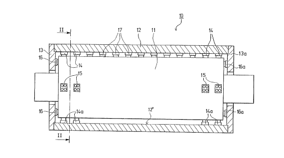
Figure 2 is a schematic sectional view taken along the line II-II in Fig. 1.
Figure 2A is a schematic perspective view illustrating an exemplifying
embodiment
of a preferred construction of axial support.
Figure 3 is an illustration corresponding to Fig. 2 of a solution alternative
to the
embodiment shown in Fig. 2.
Figure 4 is a more detailed and partly sectional illustration of the support
of the roll
mantle and of the control of the movements of the roll mantle in the so-called
principal loading direction when accomplished in accordance with the
invention.
Thus, Figs. 1 and 2 are fully schematic sectional views of a tubular roll with
glide
bearings in accordance with the invention so that Fig. 1 is a sectional view
of the
roll in the axial vertical plane, and Fig. 2 is a sectional view of the roll
of Fig. I
taken along the line II-II in Fig. 1. In Figs. 1 and 2 the roll is denoted
generally
with the reference numeral 10, and in these embodiments the roll 10 is a
variable-
crown roll, preferably adjustable in zones, which roll comprises a stationary
roll axle
CA 02239189 1998-06-O1
WO 98/17862 PCT/FI97/00621
7
11, on which the tubular roll mantle 12 has been fitted revolvingly, which
roll
mantle is supported on the roll axle by means of hydraulic loading elements
17. The
hydraulic loading elements 17 act in the so-called principal loading
direction, i.e. in
the direction of the nip plane, and by means of said elements it is possible
to adjust
the shape of the roll mantle 12 and to control the axial nip profile of the
roll.
The roll 10 shown in Figs. 1 and 2 is a roll exclusively provided with glide
bearings, so that the roll 10 has no conventional roller contact bearings
fitted at the
roll ends at all. The journalling of the roll 10 has been accomplished by
means of
glide bearing elements, of which the glide bearing elements that act in the
loading
direction, in the case of the roll shown in Figs. 1 and 2 in the direction of
the nip
plane, are denoted with the reference numerals 14 and 14a. The first glide
bearing
elements 14 act in the direction of the nip, i.e. against the loading, and the
second
glide bearing elements 14a act in the opposite direction. In the exemplifying
embodi-
ment shown in Figs_ 1 and 2, it is shown further that the roll 10 is also
provided
with glide bearing elements 15,15a acting in the direction transverse to the
loading
direction, which elements act in opposite directions. Since the roll 10 is a
roll
exclusively provided with glide bearings, it is also provided with glide
bearing
elements 16,16a acting in the axial direction in opposite directions, which
elements
16, I6a are supported by the intermediate of an oil film against the roll ends
13,13a.
As is shown in Figs. 1 and 2, the glide bearing elements I4,15,14a,15a acting
in the
radial direction are supported against the inner face 12' of the roll mantle
12 by the
intermediate of an oil film. In the illustration in Fig. 1, the glide bearing
elements
14,14a,15,15a that act in the radial direction have been arranged in pairs, so
that
there are two pieces of each glide bearing element, which have been fitted
side by
side in the axial direction. From the point of view of the operation, such an
arrange-
ment is, however, not an indispensable requirement, for the journalling can
also be
accomplished, for example, by means of single glide-bearing elements alone, or
by
means of several glide bearing elements fitted side by side.
On the other hand, in Fig. 2 it is shown that the glide bearing elements
14,14a,
IS,lSa have been arranged to act in the direction of loading and in the
direction
CA 02239189 1998-06-O1
WO 98/17862 PCT/FI97/00621
transverse to said loading direction. However, there may also be a higher
number of
glide bearing elements fitted to act radially in different angular positions.
One such
alternative embodiment is illustrated in Fig. 3.
Thus, said Fig. 3 illustrates a case in which the support of the roll mantle
12 in the
transverse direction has been arranged in a way similar to that described in
relation
to Fig. 2, i.e. by means of glide bearing elements 15,15a acting in opposite
direc-
tions. In stead, the supporting of the roll mantle 12 in the principal loading
direc-
tion, i.e. in the direction of the nip plane A, has been accomplished so that,
in the
solution shown in Fig. 3, glide bearing elements 14',14";14'a,14"a axe
employed,
which do not act directly in the principal loading direction A but are
diverted from
said direction by the angle « in opposite directions. The solution shown in
Fig. 3 is
advantageous in particular in the respect that by means of said solution a
force is
achieved that is higher than with the construction shown in Fig. 2, because
the
resultant of the forces of the glide bearing elements 14',14" and 14'a,14"a,
respect-
ively, acts in the principal loading direction A. In all other respects, the
embodiment
shown in Fig. 3 is similar to that described above.
In respect of the axial glide bearing elements, it can be stated further that,
differing
from Fig. 1, the axial movements of the roll mantle t? tea" hp ..n.,trnTlA,~
h.. ....,o"~~
of single glide bearing elements 16, I6a alone, acting in the same plane in
opposite
directions. On the other hand, there may also be several such axial glide
bearing
elements 16,16a, which are, for example, uniformly spaced and divided so as to
act
upon the inner faces of the roll ends I3,13a. Fig. 2A shows a further, more
advan-
tageous embodiment of axial glide bearing elements. According to this
embodiment,
the axial glide bearing elements 16b are annular glide bearings, into whose
support
face, which rests against the roil end 13,13a, oil pockets 44 have been
formed. '
Similarly, in the exemplifying embodiment shown in this figure, an annular
groove
16c has been formed into the roll axle 11, into which groove the "piston part"
of the
glide bearing element 16b has been fitted. The axial support can also be
arranged so
that glide bearing elements I6b are supported from opposite sides against the
same
CA 02239189 1998-06-O1
WO 98/17862 PCT/FI97l00621
9
roll end 13, in which case axial glide bearings are not needed at the opposite
end of
the roll.
Fig. 4 is a schematic and partly sectional illustration of the support of the
roll mantle
in the so-called principal loading direction, i.e., in the case of the
variable-crown
roll 10 adjustable in zones shown in Fig. i, in the direction of the nip
plane. In Fig.
4 the nip plane is denoted with the reference denotation A. Also in this Fig.
4 which
is being discussed now, the roll axle is denoted with the reference numeral 11
and
the roll mantle with the reference numeral 12. In the following, to begin
with, the
construction of the support arrangement shown in Fig. 4 will be described, and
after
that the operation of the support arrangement will be described.
The roll mantle I2 is supported by means of glide bearing elements 14,14a
loaded
against the inner face 12' of the roll mantle, which bearing elements act, in
the
embodiment shown in Fig. 4, in opposite directions so that the first glide
bearing
element 14 loads the roll mantle I2 towards an outside load applied to the
roll
mantle, i.e., in the case shown in Fig. 1, towards the nip, and the other
glide
bearing element 14a loads the roll mantle similarly in the opposite direction.
Thus,
in the case of Fig. 4, the glide bearing elements 14,14a have been arranged in
the
nip plane A to act in opposite directions. The glide bearing elements 14, I4a
are
provided with cavity spaces 21,21a that can be pressurized, and for each glide
bearing element 14,14a frame pieces 20,20a have been mounted in the roll axle
11,
which pieces penetrate into the cavity spaces 21,2Ia in said glide bearing
elements,
in relation to which cavity spaces the frame pieces 20,20a have been sealed by
means of seals 22,22a so that the glide bearing elements 14,14a can move in
relation
to the frame pieces 20,20a in the radial direction of the roll. Moreover, the
frame
' pieces 20,20a have been shaped so that the glide bearing elements I4,14a can
be
inclined in relation to the frame pieces 20,20a.
As regards their construction, the glide bearing elements 14,14a are in the
respect
conventional that their outer faces are provided with oil pockets 24,24a, into
which
lubrication oil or an equivalent oil material is fed through capillary bores
25,25a
CA 02239189 1998-06-O1
WO 98/17862
PCT/FI97/00621
passing through the glide bearing elements I4,14a. To the bottoms of the
cavity
spaces 21,21a in the glide bearing elements 14,14x, bottom pieces 23,23a have
been ,
attached by means of purposeful fastening means (not shown). Thus, the bottom
pieces 23,23a move along with the glide bearing elements 14,14a so that, in
relation
5 to the frame pieces 20,20x, they can both be inclined and move in the radial
direction of the roll. Into the bottom pieces 23,23x, into the side placed
facing the
frame pieces 20,20x, i.e, inwards in the radial direction, cylindrical
recesses 26,26a
have been formed, and further, into the bottom pieces 23,23x, bores 23',23'a
have
been formed which communicate with said recesses 26,26a and pass through the
10 bottom pieces 23,23x. The lubricant is passed through said recesses 26,26a
and
bores 23',23'a into the capillary bores 25,25a and from them further into the
oil
pockets 24,24x.
In a roll with glide bearings in accordance with the invention, the
lubrication and
loading of the glide bearing elements 14,14a have been separated from one
another.
The pressure medium intended for loading of the glide bearing elements 14,14a
is
passed into the cavity spaces 21,21a in the glide bearing elements through
particular
pressure ducts 32,32x. On the other hand, for the supply of the lubricant
intended
for lubrication between the glide bearing elements 14,14a and the inner face
12' of
the roll mantle there are lubricant ducts 31,31a of their own. The lubricant
ducts
31,31a communicate with the glide bearing elements 14,14a through the ducts
28,28x. The duct 28,28a is a tubular member, in whose end placed next to the
axle
11 there is a spherical articulation member 30,30x, by whose means the duct
28,28a
has been mounted on the roll axle 11 so that it is articulated and sealed, in
the case
illustrated in Fig. 4 between the axle l I and the frame piece 20,20a so that
the duct
28,28a can be inclined freely in the way required by the inclining of the
glide
bearing elements 14,14x. Further, in the case shown in Fig. 4, a "socket" has
been
formed into the frame piece 20,20a for the spherical articulation member
30,30x, in
which socket said articulation member can pivot, and further the frame piece
20,20a
has been sealed by means of a seal 27,27a in relation to the roll axle 11. At
the
opposite end of the duct 28,28x, i.e. at the end placed next to the glide
bearing
element 14,14x, there is a piston member 29,29x, which has been fitted in the
CA 02239189 1998-06-O1
WO 98/17862 PCT/FI97/00621
11
cylindrical recess 26,26a formed in the bottom piece 23,23a so that, when the
glide
bearing element I4,14a moves in the radial direction, the piston member 29,29a
moves in the cylindrical recess 26,26a. Moreover, the piston member 29,29a has
been shaped so that said piston member 29,29a and the cylindrical recess
26,26a can
be inciined in relation to one another. Further, the piston member 29,29a is
provided
with a seal passing around the piston member, which seal is sealed against the
wall
of the cylindrical recess 26,26a. Thus, the supply of the lubricant to the
glide
bearing elements I4, I4a is completely separated from the supply of the
pressure
medium.
By means of the construction in accordance with the invention, a controlled
and
precise regulation of the position of the roll mantle 12 in the direction of
the nip
plane A is achieved. This is highiy significant, for example, in connection
with rolls
of supercalenders, because during the operation of a supercalender situations
occur
in which it must be possible to keep the roll in the desired position even if
the
loading pressure of the stack of rolls had been switched off. Such situations
may
occur, for example, during web breaks in connection with instantaneous
opening. In
a case in accordance with the present invention, this can be arranged simply
by
opening and closing the flow in the pressure duct 32,32a. In such situations,
it is not
necessary to interfere with the supply of lubricant at all, in which case the
lubrica-
tion between the glide bearing elements 14, I4a and the inner face I2' of the
roil
mantle is ensured under all circumstances. A significant advantage is achieved
further by means of the solution in accordance with the invention in the
respect that
the pressure of the lubricant passing to the glide bearing elements 14, I4a
can be
arranged adjustable, in which case, by means of said regulation of the
lubricant
pressure, it is possible to regulate the flow passing through the glide
bearing
elements 14,14a. This property can be utilized in the regulation of the
temperature
in the roll mantle 12, and in particular in the end areas of the roll mantle.
In a
number of cases, it is necessary to be able to cool exactly said end areas
during
operation, and in the solution in accordance with the present invention this
takes
place simply by regulating the pressure of the lubricant. The regulation of
the
pressure of the lubricant can be arranged to be common of all the glide
bearing
CA 02239189 1998-06-O1
WO 98/17862 PCT/FI97/00621
I2
elements 14, I4a in the nip plane A. On the other hand, the regulation of the
lubricant pressure can be arranged separately and individually for each glide
bearing
element 14,14a in the nip plane, and also for the hydraulic loading elements
17
proper if a corresponding construction is used in these, in which case the
axial ,
temperature profile in the roll can be affected by means of such a possibility
of
regulation.
As was stated earlier in connection with nip rolls, it must be possible to
shift the roll
mantle quickly in the direction of the nip plane, for example, when the nip is
opened
(and also when it is closed). Earlier, such quick opening of the nip has been
con-
trolled, among other things, so that a separate braking pressure has been
passed into
the glide bearing elements, by whose means, for example in a situation of
opening
of the nip, it has been possible to stop the glide bearing elements in the
desired
position in a controlled way even if the loading pressures had been switched
off
IS completely. In the solution of the present invention, no such separate
braking
pressure is needed at all any longer, but the movements of the glide bearing
elements
14,14a and of the roll mantle 12 have been arranged exclusively by regulating
the
flow in the pressure duct, for example, by means of a suitable throttle.
Lubrication
has been ensured also in all such situations, because the supply of lubricant
need not
be switched off.
Above, the invention has been described by way of example with reference to
the
figures in the accompanying drawing. The invention is, however, not confined
to the
exemplifying embodiments illustrated in the figures alone, but different
embodiments
of the invention can show variation within the scope of the inventive idea
defined in
the accompanying patent claims.