Language selection

Search

Patent 2239236 Summary

Third-party information liability

Some of the information on this Web page has been provided by external sources. The Government of Canada is not responsible for the accuracy, reliability or currency of the information supplied by external sources. Users wishing to rely upon this information should consult directly with the source of the information. Content provided by external sources is not subject to official languages, privacy and accessibility requirements.

Claims and Abstract availability

Any discrepancies in the text and image of the Claims and Abstract are due to differing posting times. Text of the Claims and Abstract are posted:

  • At the time the application is open to public inspection;
  • At the time of issue of the patent (grant).
(12) Patent Application: (11) CA 2239236
(54) English Title: CONNECTION OF AN END PIECE WITH A CARDBOARD TUBE CORE
(54) French Title: RACCORDEMENT D'UNE PIECE D'EXTREMITE AVEC LE MANDRIN D'UN TUBE DE CARTON
Status: Dead
Bibliographic Data
(51) International Patent Classification (IPC):
  • B65H 75/22 (2006.01)
  • B41J 32/00 (2006.01)
  • B41J 33/00 (2006.01)
  • B65H 75/08 (2006.01)
  • B65H 75/30 (2006.01)
(72) Inventors :
  • BURGIN, MARKUS (Switzerland)
(73) Owners :
  • PELIKAN PRODUKTIONS AG (Switzerland)
(71) Applicants :
  • PELIKAN PRODUKTIONS AG (Switzerland)
(74) Agent: BERESKIN & PARR
(74) Associate agent:
(45) Issued:
(22) Filed Date: 1998-05-29
(41) Open to Public Inspection: 1998-12-02
Examination requested: 2000-05-24
Availability of licence: N/A
(25) Language of filing: English

Patent Cooperation Treaty (PCT): No

(30) Application Priority Data:
Application No. Country/Territory Date
197 23 076.8 Germany 1997-06-02

Abstracts

English Abstract


A tube-shaped stub (5) of the end piece (2) is inserted into the core (1). The stub (5)
has, adjacent to the free end, hook-like projections (11). This achieves secure
anchoring of the end piece (2) in the core (1), even under changing climatic conditions.


French Abstract

Ergot (5) en forme de tube de la pièce d'extrémité (2) introduit dans le mandrin (1). L'ergot (5) possède près de l'extrémité libre des parties saillantes en forme de crochet (11). Elles permettent d'assurer l'ancrage de la pièce d'extrémité (2) dans le mandrin (1), même en cas de changement dans les conditions climatiques.

Claims

Note: Claims are shown in the official language in which they were submitted.


Claims
1. Connection of an end piece (2) with a cardboard tube core (1), whereby
a tube-shaped stub (5) of end piece (2) is inserted in core (1),
characterized in that stub (5) has at least one, at least in fully inserted
position, the exterior circumference (10) of stub (5) protruding part (11, 20, 30),
whose outer periphery tapers toward the free end of core (1).

2. Connection according to Claim 1, whereby stub (5) has no slot and has several hook-like projections (11) distributed over the circumference.

3. Connection according to Claim 2, whereby in the extension of the projections (11)
there are arranged swallow-tail-shaped longitudinal ribs (7) at the exterior
circumference (10) of stub (5).

4. Connection according to Claim 1, whereby stub (5) is slotted and in its free
end is inserted a spreader element (17) and whereby anchoring elements (7, 20)
are distant from the outer circumference of stub (5).

5. Connection according to Claim 4, whereby the anchoring elements are
longitudinal ribs (7).

6. Connection according to Claim 1, whereby stub (5) has a longitudinal slot (25)
in which engages a double-armed tiltable lever (26), whose first arm (28) in
its basic position, next to flange (3) projects beyond the outer circumference (10)
of stub (5) with a plane (29) inclined toward the axis of stub (5), and whose
second arm (30) has a hook (31) which, when the first arm (28) is
pressed in, protrudes beyond the outer circumference of stub (5).


Description

Note: Descriptions are shown in the official language in which they were submitted.


CA 02239236 1998-05-29


Conn~tion of ~n Fntl Piece with a ~rdho~rd Tube Core

Wlde color ribbons, for example for telex machines, are usually wound on
cardboard tube cores. In order to support, put into motion or brake these cores in a
printer, end pieces with a tube-shaped stub are inserted at both eAI~ lilies. These
are made of plastic. It has been demonstrated that specifically under c~l~nging climatic
conditions, these end pieces are not securely enough coMected to the core.

The present invention has the objective of ~li",;nAt;~g this dl~z~. This objective
is solved by a co.,l~h~ation of characteristics of the claims. In the following, exemplary
embodiments of the invention are explained, based on the drawing. The drawing
shows:

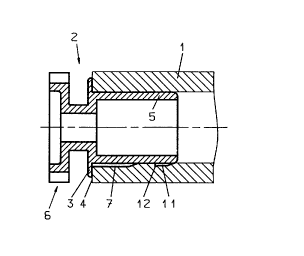
Figure 1: an axial section through a first specific embodiment
Figure 2: a front view of the bearing part,
Figure 3: a lateral view of a portion of the bearing part, and
Figures 4 }
and 5 }: twoadditional specificembodiments.

The specific embodiment according to Figures 1 to 3 consists of a circular-cylindrical
cardboard tube core 1 and bearing parts 2 inserted in same on both sides. The bearing

CA 02239236 1998-05-29


part 2 has a flange 3 which abuts the front surface 4 of core I and which has a tube-shaped
stub 5, which is inserted in the core 1. One of the two bearing parts 2 of the wind-up
spool additionally has a formed-on toothed wheel 6. Uni~ol~llly distributed over the
circumference extend, over app-o~l~lely half of the length, starting from Flange 3,
longitudinal ribs 7, which, in cross-section, are swallow-tail shaped, and which pass,
at their free end, in the form of a cone, into the exterior surface 8 of stub 5. The
outer flanges 9 of the lol ~t~l~lin~l ribs 7 are appro~,l,lalely radially oriented and pass
angularly into the V-shaped recess: Thus, bearing part 2 and core 1 are joined to each
other torsion-proof. In the extensions of these ribs 7, hook-like or sa~,v-toothshaped
projections 11 are formed on the exterior surface 8. The steep flange of tooth 12 is
oriented toward flange 3. Following in~t~ tion, projections 11 wedge thernselves in
core 1. Thus, permanent hold of bearing part 2 in core 1 is a~ -ed.

In the specific embodiment a~c~rdillg to Figure 4, ribs 7 are continuous. Stub 5 has
several longitudin~l slots 16, distributed over the circulllrelence. Into the free end of
stub 5 is inserted a spreader elem~nt 17 in form of a casing 18 with a lid 19.
The free end of stub S is thus somewhat spread out. Tests have shown that specifically
after several weeks of embed,l,ent time, sufficiently rigid conn~lion in axial direction is
att~ine~ between support element 2 and core 1 because the somewhat spread-out free
ends 20 of ribs 7 settle in the cardboard of core 1.

In the specific embodiment according to Figure 5, stub 5 has a longitudinal slot 25.
A double-armed lever 26 is inserted in stub 5, which is rotatable around an axis 27.
The one, longer lever arm 28 protrudes, in unmounted state, next to the flange 3,
beyond the outer surface 10 with plane 29 inclined toward the axis of the stub.
The shorter lever arm 30 is hook-shaped. Irnmediately prior to flange 3 being positioned
against the front surface 4, arm 28 is pressed in and the lever 26 swivelled in arrow

. CA 02239236 1998-05-29


direction, so that hook 31 of arm 30 enters into core 1. A secure connection is thus
achieved. At one location of the circumference, core 1 has, starting from the front
surface 4, a longitudinal slot 37. Said lon~ iin~l slot engages a ret~ining strip, which
is formed onto stub 5, and which is slightly cone-shaped at its interior end. This
achieves a secure, torsion-proof connection. It is, however, also possible to omit
slot 37 and strip 36, and to provide instead longitu~1in~1 ribs 7, as in the specific
embodiment according to Figures 1 to 3.
Representative Drawing
A single figure which represents the drawing illustrating the invention.
Administrative Status

For a clearer understanding of the status of the application/patent presented on this page, the site Disclaimer , as well as the definitions for Patent , Administrative Status , Maintenance Fee  and Payment History  should be consulted.

Administrative Status

Title Date
Forecasted Issue Date Unavailable
(22) Filed 1998-05-29
(41) Open to Public Inspection 1998-12-02
Examination Requested 2000-05-24
Dead Application 2003-05-29

Abandonment History

Abandonment Date Reason Reinstatement Date
2002-05-29 FAILURE TO PAY APPLICATION MAINTENANCE FEE

Payment History

Fee Type Anniversary Year Due Date Amount Paid Paid Date
Registration of a document - section 124 $100.00 1998-05-29
Application Fee $300.00 1998-05-29
Request for Examination $400.00 2000-05-24
Maintenance Fee - Application - New Act 2 2000-05-29 $100.00 2000-05-24
Maintenance Fee - Application - New Act 3 2001-05-29 $100.00 2001-05-24
Owners on Record

Note: Records showing the ownership history in alphabetical order.

Current Owners on Record
PELIKAN PRODUKTIONS AG
Past Owners on Record
BURGIN, MARKUS
Past Owners that do not appear in the "Owners on Record" listing will appear in other documentation within the application.
Documents

To view selected files, please enter reCAPTCHA code :


To view images, click a link in the Document Description column. To download the documents, select one or more checkboxes in the first column and then click the "Download Selected in PDF format (Zip Archive)" or the "Download Selected as Single PDF" button.

List of published and non-published patent-specific documents on the CPD .

If you have any difficulty accessing content, you can call the Client Service Centre at 1-866-997-1936 or send them an e-mail at CIPO Client Service Centre.


Document
Description 
Date
(yyyy-mm-dd) 
Number of pages   Size of Image (KB) 
Representative Drawing 1998-12-07 1 6
Abstract 1998-05-29 1 7
Description 1998-05-29 3 86
Cover Page 1998-12-07 1 31
Drawings 1998-05-29 2 33
Claims 1998-05-29 1 34
Assignment 1998-05-29 3 119
Prosecution-Amendment 2000-05-24 1 35
Prosecution-Amendment 2000-06-15 2 74
Fees 2000-05-24 1 34
Fees 2001-05-24 1 32