Note: Descriptions are shown in the official language in which they were submitted.
CA 02239240 2004-10-04
,.
P-US-TN-0976
llvIPROVED SELF-CENTERING DRILL BIT
WITH PILOT TIP. AND PROCESS
10 ~ FIELD OF THE INVENTION
The invention relates to twist drill bits having flutes that extend from a tip
of the drill
bit to a termination point on the shank. The drill bit flutes define a web
thickness which
increases along the length of the flute from the tip to the termination point.
The invention uses
a much steeper web taper rate than is used in the industry. It has been
discovered that bits
employing the present invention experience significantly enhanced toughness
and resistance to
breakage in metal, yet ,still perform well in wood. This enhanced effect is
particularly
pronounced when the drill bit is driven by a portable drill.
BACKGROUND OF THE INVENTION
Conventional wisdom in the art holds that it is advisable to use a relatively
shallow web
taper rate in twist drills so that the flute depth along the length of the
flute is as great as
practicable. This should provide the maximum amount of volume to convey chips,
swarf or
sawdust back from the tip and out of the hole being drilled. This convention
is embodied in
two Standards: The American Society of Mechanical Engineers (ASME B94.11M-
1993),
and The National Aerospace Standard of the Aerospace Industries Association of
America,
Inc., (NAS 907) (hereinafter collectively referred to as "Standards"). The
Assignee of the
present invention has been selling conventional Jobber-length, straight-shank
drill bits which
have parameters that track the Standards, and which have conventional web
thickness taper
rates between 0.024 inches to 0.030 inches. Also, it has been selling a self
centering drill bit
~~ Pilot tip under the BULLET~ trademark having a web taper rate of about
0.027 inches
per inch of flute length. This self centering drill bit was designed with the
end user who uses a
CA 02239240 2004-10-04
r
P-US-TN-0976
portable drill in mind, particularly one who desires a bit which is optimized
to drill in both
metal and wood. The first versions of these bits are disclosed in U.S. Patent
Nos. 4,968,193,
issued November 6, 1990, to Chaconas et al., and 5,288,183, issued Febn.~ary
22, 1994, to
Chaconas et al.. each of which is assigned to the same Assignee of the present
invention.
One of the needs of an operator who uses the bit in a hand-held power drill is
increased
toughness, or resistance to breaking (typically in the flute portion of the
drill bit). The
increased robustness is needed because in metal drilling the portable power
drill user puts
considerable side stresses on the drill bit, not having the stability that a
drill press provides.
However, the BULLET~ drill bit, which was optimized to drill well both in
metal and in
wood, not only needs strength while drilling metal, it also must drill holes
through wood with
a minimum of "woodpeckering", that is, repetitively retracting and reinserting
the drill bit to
clear the flutes of sawdust. There is also a need to enhance the BULLET~
drill, bit's longevity
if it should be subjected to an overspeed condition in metal, as well as the
strength in its tip
portion. Finally, there is a need to reduce its tendency to produce a disc in
laminated
materials.
SLnvIMARY OF THE INVENTION
It has been discovered that by defying convention, and instead, using a
radically-
increased web taper rate, a much more robust drill bit will be created. In
addition, it has been
discovered that a particular range of increased web taper rates will not only
provide
sufficiently enhanced robustness or strength when drilling in metal, it
simultaneously provides
a bit which minimizes the amount of woodpeckering required when drilling wood.
Accordingly, it is an object of the present invention to manufacture a twist
drill bit having a
web thickness taper rate over the length of the flute which is about twice as
great as the web
taper rate of conventional drill bits, thereby providing significantly
increased resistance to
breakage while drilling in metal, yet, for drill bits having nominal diameters
of 0.250 inch or
greater, enabling the user to drill holes in inch and one-half thick wood in
one pass.
It is a particular object of the preferred embodiments of the invention to
provide a
twist drill bit in which the web thickness increases from the tip to the shank
portion at a
uniform taper rate along the length of the flute in the range from about 0.050
inch to about
2
CA 02239240 1998-08-26
P-US-TN-0976
0.071 inch per inch of flute length. It is yet another particular object of
the preferred
embodiments of the invention to provide a bit marking zone on the shank
portion of the drill
bit which is outside of the area of the shank typically gripped by the jaws of
a chuck in which
the drill bit is inserted.
A feature by which the above objects may be attained is by forming the flutes
with the
web taper rate of the present invention along a flute length which is less
than the flute length
specified for a predetermined bit nominal diameter by the ASME B94.11-M-1993
Standard,
and specifically by reducing the flute length by about 0.3 inch to about 0.7
inch. Optimally,
the flute length is reduced by about one-half inch, for all nominal diameters
of the drill bits. A
preferred feature is to form indicia such as the nominal size of the bit, in
the marking zone, so
that in the engagement by the chuck of the bit shank does not erase the
indicia.
Another feature by which the above objects can be attained is in the
manufacturing
process: causing relative axial movement between a grinding wheel and drill
bit stock while
rotating the drill bit stock about its axis, grinding the flute having the
desired flute length with
the web thickness taper rate of the present invention, then retracting the
grinding wheel from
the drill bit stock upon reaching a point which is a predetermined distance
before the point at
which the flute would terminate at the shank if the taper rate were to be
maintained.
It is yet another object of the present invention to enhance the robustness of
self
centering drill bits with pilot tip of the type sold under the trademark
BULLET~. One feature
by which the above object can be attained is by optionally providing the drill
bit tip portion
with a fishtail angle of less than 180°. Yet another preferred feature
is to form a chamfer
adjacent the fishtail such that a cutting edge on the chamfer connects a
cutting lip on the
fishtail with the outer diameter of the drill bit. Still another preferred
feature is to provide the
pilot portion with a back taper in the axial direction. Another preferred
feature is to provide a
back taper which is at least 1° negative. And yet another feature is to
size the width or
diameter of the pilot portion to be about one-half the nominal bit diameter.
Other objects, features and advantages of the present invention will become
more fully
apparent from the following detailed description of the preferred embodiments,
the appended
claims and the accompanying drawings.
CA 02239240 1998-08-26
P-US-TN-0976
BRIEF DESCRIPTION OF THE DRAWINGS
In the accompanying drawings, in which like reference characters in the same
or
different Figures indicate tike part:
FIG. 1 is a side elevational schematic view of a conventional drill bit to
which a force F
S is applied to such an extent that the bit breaks, usually in the flute
portion;
FIG. 2 is a side elevational schematic view of a twist drill bit according to
the present
invention in which a much higher force F must be applied to break the drill
bit;
FIG. 3 is a side elevational schematic view of a twist drill bit according to
another
embodiment of the present invention to which a force F is applied to cause the
bit to break
outside the flute portion;
FIG. 4 is a schematic detail view of the drill bits of FIGS. 2 and 3
superimposed upon
the drill bit of FIG. 1, employing the web taper rates of the present
invention;
FIG. 5 is similar to FIG. 4, but illustrating solely a web taper rate of the
present
invention, in combination with a pilot tip of the present invention;
FIG. 6 is similar to FIG. 5, but illustrating the web taper rate of the
present invention
in a conventional twist drill bit;
FIG. 7 is a view similar to the view of FIG. S, illustrating an embodiment of
the present
invention in which the flute length is the same as the conventional flute
length;
FIG. 8 is an elevational schematic view of the process for forming the web
taper rate
of the present invention;
FIG. 9 is an elevational detail schematic view of the tip portion of a self
centering drill
bit having a pilot tip;
FIG. 10 is one embodiment of an improved tip portion according to the present
invention;
FIG. 1 I is another embodiment of the tip portion of the present invention;
FIG. 12 is yet another embodiment of the tip portion according to the present
mventron;
FIG. 13 is still another embodiment of the tip portion of the present
invention;
FIG. 14 is partial enlarged elevational detail view of the bit of FIG. 9
rotated to
illustrate a secondary lip relief angle ("F2"); and
FIG. 15 is an enlarged schematic detail view of the process for forming a
portion of the
tip portion of FIG. 9.
4
CA 02239240 1998-08-26
P-US-T'N-0976
DETAILED DESCRIPTION OF PREFERRED EMBODIMENTS
Referring first to FIG. 1, a conventional twist drill bit is shown generally
as 10, and
includes a shank portion 12, a flute portion 14 containing two flutes 16 and a
tip portion 18.
When drilling in metal with a portable power drill, the drill bit 10
encounters greater than
normal forces F transverse to the axis of the drill bit, as shown
schematically in FIG. 1. If the
force F is great enough, the drill bit will break or fail as shown at 1 S.
Tests run on a quarter
inch diameter conventional twist drill bit 10 found that the failure 1 S
occurred primarily in the
fluted portion 14, when the bit was subjected to a peak force at failure in
the range from 150
to 175 lbs.
A twist drill using the taper rate of the present invention is shown generally
as 20 in
FIG. 2, and includes shank portion 22, flute portion 24 having two flutes 26,
and a tip portion
28. In tests of quarter inch nominal diameter twist drill bits incorporating
the taper rate of the
present invention, it took a peak force at failure in the range of 250 to 300
Ibs. to break the
bit. In most cases the break occurred not in the fluted portion 24, but in the
strongest part of
the bit, namely the shank portion 22. This result was attained using the same
hardness of the
bit steel as conventional bits. The first three quarters of the fluted portion
is maintained at full
hard, decreasing to a lesser hardness from that point to the end of the shank.
FIG. 3 shows an alternate embodiment of a twist drill incorporating the web
thickness
taper rate of the present invention, and illustrates its ability to perform
well in wood while still
exhibiting its enhanced strength while drilling in metal. It has been found
that a twist drill bit
made according to the invention shown in FIG. 3 and having a nominal bit
diameter of 1/4"
can be used to drill a hole through a 1-1/2" thick piece of wood 30, such as 2
X 4, without
withdrawing the bit to clear the sawdust from the flutes and then reinserting
the bit to finish
the hole. Thus the present invention embodied in the twist drill bit shown in
FIG. 3 reduces
the amount of "woodpeckering", so that the operator can use a 1/4" metal-
drilling drill bit to
drill a hole through the board 30 in one pass, as indicated by arrow 32. The
web taper rates of
the present invention are shown. schematically in various drill bits in FIGS.
4 through 7.
FIG. 4 schematically illustrates the web taper of the present invention (shown
in short
dashes) superimposed upon the web taper of a conventional bit (shown as long
and short
dashes). The profile of the conventional web taper is referred to as 34, and
the web profile of
the present invention is referred to as 36.
5
CA 02239240 1998-08-26
P-US-TN-0976
The most common drill bit used by the person operating a hand-held power drill
is
known as a "Jobber's-length, straight-shank drill bit", specifications for
which are common in
the industry and are set out in the Standards. These Standards collectively
set forth
commonly-accepted ranges of drill bit parameters for various nominal bit
diameters, and
further reflect conventional wisdom in the art of drill bit technology. As
previously noted,
these teachings hold that the more chips or sawdust a flute can remove from
the' hole being
drilled, the better. To that end, conventional wisdom in the art dictates that
the web thickness
should taper outwardly from the tip towards the shank at a very gradual rate.
For example,
the NAS 907 Standard specifies that the web taper rate for Types "A.", "B" and
"J" straight
shank, Jobber's length drill bits be uniform tapers of 0.017", 0.024" and
0.006", respectively,
with respective tolerances of plus or minus 0.003 ", plus or minus 0.003 ",
and plus or minus
0.002", respectively. Indeed the taper rates of conventional bits sold by the
Assignee of the
present invention follow this teaching. For example, certain drill bits sold
under the
DeWALT~ trademark have a web taper rate of 0.024" inches per inch of flute
length for drill
bit nominal diameters up to and including 3/16", and a web taper rate of 0.030
inches per inch
of flute length for drill bits having nominal diameters greater than 3/16
inch. As previously
noted, self centering drill bits having pilot tips sold under the BIJLLI?T~
trademark have a
web taper rate of 0.027 inches per inch of flute length.
Referring once again to FIG. 4, bits following the teaching of the Standards
have flutes
along the flute portion 24 which exit at a termination point 38 with the outer
diameter of the
shank portion 22, the shank portion being defined as the portion of the drill
bit outside of the
portion that contains the flute and which is inserted in the chuck of a power
drill. Here the
web thickness of the conventional web profile 34 increased from a thickness T
to a thickness
designated by 40 at termination, leaving a relatively large flute depth 42 for
receiving the chips
or sawdust. In marked contrast, the web taper profile 36 of the present
invention exits the bit
20 at a flute termination point 44. This provides a much thicker web 46 at the
flute
termination point 44 and yields a very small flute depth 48 at that point.
Note that the flute
grinding wheel has left a relatively large radius portion 50 at the
conventional flute termination
point 38, but a relatively small radius 52 at the flute termination point 44
of the present
invention.
6
CA 02239240 1998-08-26
P-US-T'N-097G
In one embodiment of the present invention a uniform web taper rate of 0.058
inch per
inch of flute length was found to provide durability that far exceeded
expectations. The peak
transverse force F at failure applied to a rotating cantilever-mounted drill
bit exceeded 250 Ibs.
(for a 1/4 inch nominal diameter drill bit), with very acceptable chip removal
characteristics
when drilling in metal. In another embodiment of the present invention with
the same nominal
diameter, the web thickness taper rate was set at 0.054 inches per inch of
flute length (plus or
minus 0.003 inches) for all sizes of drill bits from 1/8 inch nominal diameter
to 1/2 inch
nominal diameter. Not only did the drill bit exhibit the same strength
characteristics, but it
reduced the amount of woodpeckering when drilling wood. It was able to drill a
hole in 1-1/2
inch thick wood (such as a 2 X 4) in one pass. The web thickness T at the tip
or point in the
preferred embodiment generally follows the NAS 907 Standard, and for that
matter, the other
parameters of bits according to the preferred embodiments generally follow one
or more of the
Chaconas et al. teachings or the Standards, unless otherwise specified herein.
The other drill bit parameters pertaining to the drill bit shown in FIG. 4 and
to the
other embodiments are as follows: "D" stands for the nominal diameter of the
drill bit; "BL"
stands for the bit length (note that it does not extend to the tip but instead
to the axially
forwardmost point of the bit where the flute cuts the outer diameter of the
bit); "FL1" stands
for the flute length of a flute having a conventional web thickness taper rate
and is the flute
length referred to in the previously-identified Standards; and "FL2" is the
flute length of one
of the preferred embodiments of the present invention, created by diminishing
FL 1 by a
predetermined amount MZ. As will be described shortly, selecting FL2 in this
fashion confers
a double benefit upon the drill bit of the present invention.
Still referring to FIG. 4, for the most part, the parameters just: described,
and those in
the Standards, pertain to a double-flute, straight shank, Jobber's length
drill bit. However, it is
believed that the concept of the present invention will also have utility in
the environment of a
drill bit with a single flute. In that. case, instead of measuring the taper
rate of a web thickness
T, the taper rate of the shortest radial distance between the flute and the
axis 54 of the drill bit
{T/2) would be specified. In either event; the preferred web thickness taper
rate ranges from
about 0.050 inch to about 0.071 inch per inch of flute length, and the flute
length FL lies in the
range from about 0.3 inch to about 0.7 inch less than the flute length
specified by the ASME
Standard.
7
CA 02239240 1998-08-26
P-US-TN-0976
Ideally, MZ is about 1/2 inch for all nominal bit diameters in the range of
from 1/8 inch
through 1/2 inch. Although it is anticipated that the web taper rate of the
present invention
will do well in a drill bit having a conventional chisel point or web-thinned
point (such as a
split point) as schematically shown in FIG. 6, it is particularly useful in
the unitary
S metal/wood-drilling, self centering drill bit with pilot tip developed by
the Assignee of the
present invention, and as further described in the Chaconas et al. patents
cited above. These
embodiments of the drill bits incorporated the web-taper rate of the present
invention are
shown in FIGS. 4 and S, which bits can be equipped with any of the tip
portions 28 shown in
FIGS. 9 through 13.
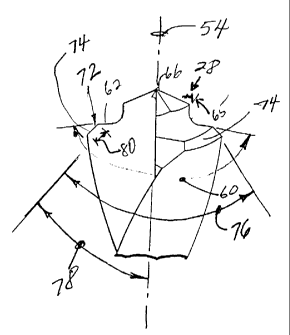
The nomenclature of the parameters for these embodiments are noted in FIGS. 9
and
11. The tip portion 28 includes a fishtail portion 56 and a pilot portion 58
extending axially
outwardly from the fishtail portion. The fishtail portion 56 includes fishtail
cutting lips 62
arranged at a fishtail angle 60. In this embodiment, the cutting lips extend
from the pilot
portion to the outer diameter ofthe drill bit. The pilot portion 58 extends a
distance "L" from
the fishtail portion 56, and has a diameter "d" smaller than the nominal
diameter "D" of the
drill bit. The pilot portion 58 defines an annular pilot wall 64 which is both
radially and
axially relieved as taught in the above-identified Chaconas et al_ patents.
The pilot portion 58
is formed with pilot cutting lips arranged at a point angle 68 (for example
135°) and, in the
preferred embodiment, defines a split point 66. The pilot portion 58 is joined
to the fishtail
portion 56 with a radially-relieved fillet 70 having a radius "R" The drill
bit has the following
parameters: the fishtail angle 60 is greater than 180°, namely about
190°, and the pilot wall 64
defines an axial back taper 65 of about 5°. For the purposes of this
description, the back
taper on the pilot 58 which is directed radially inwardly from the point end
66 of the bit 20
toward the fishtail portion 56 will be considered a "positive" angle, whereas
a back taper
which is directed radially outwardly, as identified as 67 in FIG. 13, will be
considered a
"negative" back taper angle. A negligible back taper angle is shown as 69 in
the embodiment
shown in FIG. 12. For the purposes of this description, "negligible" means in
the range from
greater than minus 1° to less than positive 1°. Other parameters
noted in FIG. 9 are also used
in the embodiments shown in FIGS. 10 through 13 and include the pilot length
"L", pilot
diameter "d" and point angle 68.
Referring now to the embodiment shown in FIG. 10, it was discovered that the
fishtail
portion 56 will exhibit increased longevity if the fishtail angle 60 is
reduced to lie in the range
8
CA 02239240 1998-08-26
P-US-TN-0976
from about 168° to about 182°, and preferably about 170°.
Lt has also been discovered that
the pilot portion 58 will exhibit increased longevity if its diameter d is
approximately one-half
the nominal bit diameter D.
Yet another discovery was made that adding a chamfer portion 72, as shown in
FIG.
11, significantly improves the life of the bit 20 if it were to be run at an
overspeed condition.
The chamfer portion 72 includes at least one chamfer 74, and in the preferred
embodiment
includes two chamfers. The chamfers 74 are oriented at a chamfer angle 76
which is in the
range of from about 75° to about 140°, and is preferably about
90°. In the single-chamfer
embodiment, the chamfer angle 78 is about 45°, or one-half the two-
chamfer included angle
76. The length of the chamfer 80 is in the range of from about 5% to about 1
S% of the
nominal diameter and is preferably about 10%. Another advantage of the chamfer
is the
significant reduction in creation of "discs" in composite materials.
Furthermore, in the
embodiment shown in FIG. 11, the included angle 68 remains at 135°, but
the preferred back
taper angle is in the range from 0° to 5.5°, with the preferred
angle being 5°. Other tip
parameters for the embodiment shown in FIG. 11 are set forth in TABLE 1.
9
CA 02239240 1998-08-26
P-US-TN-097b
TAB LE
TABLE OF TIP PARAMETERS
Nom. Bit Diam.Pilot Diam. Pilot Length Secondary Fillet Radius
(In.) (In.) (In.) Lip (In.)
D d L Relief Angle R
fZ
1/8 .067 .OS 14 .020
9/64 .072 .052 14 .020
5/32 .080 .052 14 .020
11/64 .087 .052 14 .020
3/16 .094 .052 14 .020
13/64 .102 .052 14 .023
7/32 .109 .056 14 .023
15/64 . I 17 .061 14 .023
1/4 .125 .064 14 .023
17/64 .13 3 .068 I 4 . 026
9/3 2 .141 .073 I 4 .026
19/64 148 .077 14 .026
5/16 156 .08 14 .026
21/64 .164 .085 14 .030
11/32 .172 .089 14 .030
23/64 .180 .093 l4 .030
3/8 .188 .097 l4 .030
25/64 .195 .101 l2 .035
13/32 .203 .105 12 .035
27/64 .211 .109 12 .035
7/ 16 . 2 I 9 .113 I 2 .03 S
29/64 . 227 . I 17 I 2 .03 5
15/32 .234 .121 12 .035
31/64 .242 .125 12 .03 S
1/2 .250 .129 12 .035
CA 02239240 1998-08-26
P-US-TN-097
The embodiment shown in FIG. 12 is very similar to that of FIG. I 1, except
the back
taper angle 69 is negligible. Similarly, the embodiment shown in FIG. 13 uses
a negative back
taper angle greater than minus 1°.
Referring now to FIG. 1 S, the process for generating the pilot portion 58,
the fishtail
portion 56 and the radially-relieved fillet 70 is shown. The area of the pilot
diameter relief is
shown at 82; the fillet relief area is shown at 84, and the area of frshtail
cutting lips relief is
shown as 86. It will be appreciated that in the drill bit of FIG. 1 S, a
continuous cutting edge is
created by the fishtail cutting lip 62, fillet edge 71 and pilot wall cutting
edge 65. In order to
enable these edges to cut satisfactory, they all must be provided with relief
surfaces as shown
in FIG. 15, and as discussed in Chaconas et al, cited above. To form such
surfaces, a grinding
wheel 88 having a grinding wheel face 90 is oriented with the bit axis 54,
such that the fishtail
angle 60 divided by two is in the desired range. The pilot back taper angle 65
(positive or
negative) is achieved by providing the grinding wheel 88 with a predetermined
form, which
also defines the shape of the fillet 70. To generate the desired edges and
surfaces, the bit is
positioned in the desired angular relationship to the grinding wheel 88 and is
rotated about its
axis 54 in the direction shown by arrow 92 and at the same time is moved into
the wheel in the
direction shown by arrow 94, thereby achieving the reliefs for the cutting
edge 65, 71 and 62.
The process is repeated on the opposite side of the bit to generate both sets
of cutting edges
and reliefs.
Returning now to the web thickness taper rate of the present invention, it was
discovered that a modification to the Standard flute lengths resulted in
benefits both in
reducing variations in flute length tolerances as well as in creating a
special marking zone
"MZ" where such indicia 96 as bit size may be formed, to thereby stay clear of
the jaws of the
drill chuck to which the bit is inserted (see FIG. 4). This means that the
drill chuck will not
eradicate the size markings from the shank, as often happens in conventional
drill bits.
Again referring to FIG. 8, a grinding wheel 98 is positioned at a
predetermined angle
relative to the axis 54 of drill bit 20 and is brought radially inwardly into
contact with the bit at
the tip portion 28, or starting point of the flute, as shown by arrow L00. The
bit stock 20 and
the grinding wheel 98 are then caused to have relative movement towards one
another along
an axial direction 102. In the preferred embodiment, the grinding wheel 98 is
held for
movement only in the radially inward and outward directions as shown by arrows
100, and the
bit stock 20 is moved axially into the grinding wheel. A cam then causes the
grinding wheel
CA 02239240 1998-08-26
P-US-'TN-0976
98 to move radial(y outwardly while the bit stock moves into it, thereby
creating a desired web
taper rate. If the grinding wheel 98 producing the taper rate of the present
invention were to
be retracted at the termination point 38, creating a flute length FL1
corresponding to the flute
length recommended by the Standards, the variation in manufacturing tolerances
of the
grinding wheel and bit, in combination with the taper angle, would create a
flute length FL1 of
unacceptable breadth of variability as shown at 106. Inasmuch as the flute
length is a very
important parameter in the manufacture of twist drill bits, it is preferable
to maintain such
variations to be within a plus or minus 1/8", namely 1/4", in breadth. To
reduce the variation
in flute length tolerances, it was discovered that if the grinding wheel 98
were retracted
radially outwardly at termination point 44, rather than at 38, the variation
in flute lengths
could be significantly reduced. The point of retraction is determined by the
flute length FL1
diminished by amount MZ, where MZ is in the range of from 0.3 inch to about
0.7 inch, and
preferably about 1/2 inch.
The process is completed when a second flute is formed diametrically opposite
the
flute just described using the same process. In the preferred embodiments, the
process forms a
modified parabolic flute.
Although the web thickness taper rate of drill bits of the present invention
is believed
to significantly improve the strength of drill bits having conventional point
geometry, as
schematically shown in FIG. 6, it was particularly effective in enhancing the
durability of drill
bits having tip configurations 28 shown in FIGS. 9 through 13. The coaction of
the web taper
rate, pilot width, back taper angle, and chamfer of the embodiment shown in
FIG. 1 I , will
produce a twist drill bit of significantly improved strength overall while
keeping the versatility
that has help make it a commercial success.
The above-described embodiments, of course, are not to be construed as
limiting the
breath of the present invention. Modifications, and other alternative
constructions, will be
apparent which are within the spirit and scope of the invention as defined in
the appended
claims.
12