Note: Descriptions are shown in the official language in which they were submitted.
CA 02239369 2002-03-20
20365-3872
1
DESCRIPTION
Electronic measuring device
The invention relates to an electronic measuring
device, in particular a meter, having an A/D converter and a
digital signal processing device.
WO 95/10781 discloses an electronic measuring
device in which digitized measurement signals are monitored
for a measurement error. If a measurement error occurs, a
correction pulse is produced, so that the measurement error
is compensated for. This measuring device is preferably
used for measuring consumption, in particular for a meter.
If an A/D converter is used for such an electronic
measuring device, said converter generally requires a
reference voltage source. This is also the case if a sigma-
delta modulator (SD modulator) is used. The reference
voltage must meet high requirements, since the accuracy of
the measuring device is directly dependent on the reference
voltage. High measurement accuracy therefore also requires
a precise reference voltage, which is very complicated to
produce, and it is not necessarily possible to vouch for
operational reliability.
The invention is based on the object of specifying
a measuring device which exhibits high measurement accuracy
whilst at the same time compensating for influences on the
measurements.
The invention achieves the object with an
electronic measuring device, comprising: at least one A/D
converter for receiving measurement signals including a test
voltage having a value; a reference voltage source connected
to said at least one A/D converter for operation; and a
CA 02239369 2002-03-20
' 20365-3872
2
digital signal processing device connected downstream of
said at least one A/D converter; said signal processing
device having a correction element with a first stored
reference value and a resulting first correction factor for
compensating for a measurement error in an upstream signal
detection, said correction element producing a new
correction factor when a difference exists between the first
reference value and the value of the test voltage, and the
new correction factor is one of the first correction factor
corrected corresponding to the difference, and an additional
correction factor.
In this manner, the entire measurement path for
signal detection is based on the test voltage. This means
that, for example, systematic errors, in particular the
temperature response of the A/D converter or an effect of an
upstream multiplexer, are detected and compensated for.
This produces dynamic measurement error compensation, as it
were.
It is advantageous if a first correction factor
adapted or corrected on the basis of the difference is used
as the new correction factor. This makes simple dynamic
adaptation of the correction factor possible. If necessary,
the original value can also be saved in a further store as a
precaution.
As an alternative to this, an additional
correction factor can be used as the new correction factor.
This enables the original setting and the dynamic or
instantaneous factor to be separated. The separate
correction factor is responsible for dynamic adaptation
during operation.
CA 02239369 2002-03-20
20365-3872
2a
Advantageously, means for cyclically checking the
difference or producing the new correction factor are
provided. This means that the measurement accuracy is
continuously checked and adapted in respect of a changed
reference voltage or other influences on the measurements.
In this case, the cycle times can be prescribed depending on
the measurement accuracy desired.
The measurement signals used can be current and
voltage signals, the signal processing device comprising
means for
CA 02239369 1998-06-03
-3-
metering electrical power consumption. This constitutes a
preferred application of the invention. The measuring device
is then used as a meter.
The A/D converter advantageously has a sigma-delta modulator
(SD modulator). This produces favorable interaction in terms
of precise processing of measured values.
The signal processing device preferably produces an error
signal whenever the difference exceeds a prescribed limit
value. This provides additional error monitoring.
The invention as well as other advantages and details are
described in greater detail below with reference to an
exemplary embodiment and to the drawing.
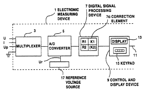
The figure shows an electronic measuring device 1 which is
preferably used as a meter for electrical power. In principle,
the measuring device can also be used for other applications,
e.g. for temperature detection and processing, in which an
analog signal is to be processed digitally.
For signal detection and processing, the measuring device 1
comprises a series circuit having a multiplexer 3, an A/D
converter 5 connected downstream of the latter and a
subsequent digital signal processing device (called device 7
below). The device 7 preferably has a microcomputer and/or a
digital signal processor for signal processing. All signal
processing is therefore carried out with the aid of programs
or program modules which may, if appropriate, also be used
twice for different functions.
The device 7 has a control and display device 9 connected to
it. This has, for example, display means or a display 13, a
keypad 15 and/or an interface 11. This provides a
CA 02239369 1998-06-03
-4-
comprehensive data input and output facility for the measuring
device 1.
Signal detection involves initially feeding measurement
signals, in particular a voltage V and a current I, to the
measuring device 1, feeding them via the multiplexer 3 to the
A/D converter 5 for digitization.
This signal detection can, of course, also be designed to be
multichannel, e.g. for detecting multiphase voltages and
currents or for detecting current and voltage separately. In
such a case, a number of multiplexers and/or A/D converters
might then be connected to the device 7 as appropriate.
In order for it to operate, the A/D converter 5 requires a
reference voltage Vr, which is a DC voltage. This is supplied
to the A/D converter from a reference voltage source 17. If
the device 1 is designed as a module or semiconductor
component, it is possible, for example, to produce the
reference voltage input of the A/D converter 5 and the output
of the reference voltage source 17 separately and, if
appropriate, connect them to one another externally using a
bridge. This makes checking operations possible, wherein a
voltage from an external voltage source can then also be
supplied to the A/D converter 5. The reference voltage source
17 is preferably a constituent part of the device 1.
The device 7 has a correction element 7a. A first correction
factor K1, which corresponds to a first stored reference value
R1, is saved in a store for the correction element 7a. In
addition, the correction factor Kl may already contain further
multiplication factors or other factors for the purpose of
(computational) simplification.
In order to set or save the reference value R1 for the first
time, as when it is set or adjusted in the factory for the
CA 02239369 1998-06-03
-5-
first time, one input of the multiplexer 3 is initially
connected, for example, to ground (shown as the ground symbol
in the figure) and the resulting digitized voltage value is
initially stored. This value corresponds to the DC component
from signal detection. The input used for this purpose may be
a special input or an input which is used for current or
voltage.
In addition, a highly accurate test signal Vt (a test voltage
used as a new reference or a new base) is applied to another
input of the multiplexer 3. The resulting difference value
between the voltage value of the DC component and the measured
value of the test signal Vt corresponds to the actual value of
the test signal Vt. This value is stored as the first
reference value R1, thereby producing the resulting correction
factor K1 for all other digitized measured values.
During operation of the measuring device 1, a further
comparison with a test signal Vt is preferably carried out at
cyclic intervals (which can be prescribed manually or
automatically). This can be produced by the same voltage
transmitter or, for example, by a voltage transmitter
installed at the location where the device 1 is installed. The
time intervals of the cycles can be prescribed as per
requirements. The corresponding digitized value is stored as
the second new reference value R2. After this, a comparison is
made between the first reference value R1 and the second
reference value R2. If they are different, a new correction
factor is determined.
This can be done such that, for example, the first correction
factor K1 is formed again or is overwritten, or that a
completely new and separate correction factor K2 is placed in
a further store which is then used for operation at that time.
This makes it possible to identify changes in the detected
measured values, so that the measurement accuracy can be
CA 02239369 1998-06-03
-6-
continuously adapted and maintained. For the first basic
setting, the correction factor K2 can be equal to K1, or may
have a default value, for example 1.
Should the difference between the values R1 and R2 exceed a
prescribed limit value, it is possible that the device 7 will
produce an error signal which will then be signalled via the
control and display device 9 or via the interface 11 to a
superordinate central control station. The error signal is
then an indication that there is a significant measurement
error.
The measuring device 1 is particularly suitable for use as a
precision meter for class 0.5 or 0.2. In this instance, the
test signal Vt fed to the measuring device 1 must be highly
accurate and satisfy the appropriate calibration or
standardization requirements.
The measuring device shown has the advantage that the entire
signal detection process or the measuring system is based on
the external test signal, in particular its reference voltage.
This obviates systematic errors, such as the effect of
temperature on the multiplexer 5 or on the switch resistance
when a sigma-delta modulator is used.
Of course, if the measuring device is used as a meter, the
relevant regulations with regard to standardization etc. have
to be taken into account. A particular application is
conceivable, for example, for detecting consumption without
any bearing on billing, e.g. in a company. The test signal Vt
can be connected to an input permanently, for example. The
test signal source necessary for this can be incorporated in
the measuring device 1 or be connected externally.
Alternatively, it is also possible to make temporary
connections or connections which are repeated at specifiable
intervals.