Note: Descriptions are shown in the official language in which they were submitted.
CA 02239425 1998-06-03
WO 97/20531 PCT/US96/18649
1
WEB MATERIALS HAVING ELASTIC-LIKE AND EXPANSIVE ZONES
f
FIELD OF THE INVENTION
~ The present invention relates to web materials, and more particularly, to
such
web materials having elastic-like and expansive zones. Web materials of the
present
invention having elastic-like and expansive zones exhibit an elastic-like
behavior in
response to an applied and subsequently released (i.e., cycled) elongation
along at
least one axis.
Web materials of the present invention have a wide range of potential uses in
both durable and disposable articles, but are particularly well suited for use
in
disposable absorbent articles such as disposable diapers, incontinent briefs,
incontinent undergarments, training pants, feminine hygiene garments, and the
like.
BACKGROUND OF THE INVENTION
Infants and other incontinent individuals wear absorbent articles such as
diapers to receive and contain urine and other body exudates. Absorbent
articles
function both to contain the discharged materials and to isolate these
materials from
the body of the wearer and from the wearer's garments and bed clothing.
Disposable
absorbent articles having many different basic designs are known to the art.
For
example, U.S. Patent Re. 26,152, entitled "Disposable Diaper", issued to
Duncan and
Baker on January 31, 1967, describes a disposable diaper which has achieved
wide
acceptance arid commercial success. U.S. Patent 3,860,003, entitled
"Contractible
Side Portions For Disposable Diaper", issued to Buell on January 14, 1975,
describes
an elasticized leg cuff disposable diaper which has achieved wide acceptance
and
commercial success.
However, absorbent articles have a tendency to sag or gap away from and to
slide/slip down on the body of the wearer during wear. This sagging/gapping
and
sliding/slipping is caused by the relative motions of the wearer as the wearer
breathes, moves and changes positions, by the downward forces generated when
the
absorbent is loaded with body exudates, and by the materials of the absorbent
article
itself when subjected to such wearer's motions. This sagging/gapping and
slidinglslipping of the absorbent article can lead to premature leakage and
poor fit of
the absorbent article about the wearer in the waist regions and the leg
regions of the
absorbent article.
In order to more snugly fit absorbent articles about the wearer, certain
CA 02239425 2000-09-20
2
commercially available absorbent articles have been provided with elastic
features. An
example of a disposable diaper with elastic side panels is disclosed in U.S.
Patent 5,151,092,
entitled "Absorbent Article With Dynamic Elastic Waist Feature Having
Predisposed Flexural
Hinge", issued to Buell, Clear, and Falcone on September 22, 1992. However,
elastics are
costly and require a certain degree of manipulation and handling during
assembly. Further,
while elastics do provide a degree of stretch for the absorbent article, the
components of the
absorbent article to which the elastics are attached are typically not elastic
such that the
elastics must be prestretched prior to being secured to the absorbent article
or the inelastic
components must be subjected to mechanical stretching (e.g., ring rolling) to
enable the added
elastic to be effective. Otherwise, the added elastic is restrained by the
inelastic comporients.
Therefore, it is an object of an aspect of the present invention to provide
relatively
low cost, easy to manufacture, web materials which exhibit an "elastic-like"
behavior in
response to an applied and subsequently released elongation. As used herein,
the term
"elastic-like" describes the behavior of web materials which when subjected to
an applied
elongation, the web materials extend in the direction of applied elongation
and when the
applied elongation is released the web materials return, to a substantial
degree, to their
untensioned condition.
It is a further object of an aspect of the present invention to provide a
relatively low
cost, easy to manufacture, absorbent article having sustained dynamic fit
about the wearer
during use.
It is a further object of an aspect of the present invention to provide an
absorbent
article having a unique extensible waist feature, preferably without the use
of elastic, that
provides sustained dynamic fit and improved resistance to leakage during use
due to the
conformability of the materials forming the waist feature by virtue of their
readily extensible
nature.
These and other objects of aspects of the present invention will be more
readily
apparent when considered in reference to the following description and when
taken in
conjunction with the accompanying drawings.
SUMMARY OF THE INVENTION
The present invention provides a web material which exhibits an elastic-like
behavior
in response to an applied and subsequently released elongation without the use
of elastic
materials such as natural or synthetic rubber. Web materials of the present
invention have an
elastic-like zone and an adjacent expansive zone.
CA 02239425 1998-06-03
WO 97/20531 PCT/US96/18649
3
The elastic-like zone is intended to elastically expand and contract. The
'' elastic-like zone preferably comprises a structural elastic-like film
(SELF) web, since
a SELF web allows the force/extension characteristics to be specifically
designed
with a minimum amount of materials (no elastic materials need to be used.)
A SELF web exhibits an elastic-like behavior in the direction of elongation
without the use of added elastic materials. SELF webs exhibit at least two
significantly different stages of controlled resistive force to elongation
along at least
one predetermined axis when subjected to an applied elongation in a direction
parallel to the predetermined axis. SELF webs include a strainable network
having at
least two contiguous, distinct, and dissimilar regions. One of the regions is
configured so that it will exhibit resistive forces in response to the applied
elongation
in a direction parallel to the predetermined axis before a substantial portion
of the
other region develops significant resistive forces to the applied elongation.
At least
one of the regions has a surface-pathlength which is greater than that of the
other
region as measured substantially parallel to the predetermined axis when the
material
is in an untensioned condition. The region exhibiting the longer surface-
pathlength
includes one or more rib-like elements which extend beyond the plane of the
other
region. SELF webs exhibit first resistive forces to the applied elongation
until the
elongation of the web is sufficient to cause a substantial portion of the
region having
the longer surface-pathlength to enter the plane of applied elongation,
whereupon the
SELF web exhibits second resistive forces to further elongation. The total
resistive
forces to elongation are higher than the first resistive forces to elongation
provided
by the first region.
SELF webs may also exhibit an elongation and recovery with a definite and
sudden increase in the force resisting elongation where this definite and
sudden
increase in resistive force restricts further elongation against relatively
small
elongation forces. The definite and sudden increase in the force resisting
elongation
is referred to as a "force wall". As used herein, the term "force wall" refers
to the
behavior of the resistive force of a web material during elongation wherein at
some
point in the elongation, distinct from the untensioned or starting point, the
force
resisting the applied elongation suddenly increases. After reaching the force
wall,
additional elongation of the web material is only accomplished via an increase
in the
elongation force to overcome the higher resistive force of the web material.
The rib-like elements allow the second region to undergo a substantially
"geometric deformation" which results in significantly less resistive forces
to an
CA 02239425 2000-09-20
4
applied elongation than that exhibited by the "molecular-level deformation" of
the first
region. As used herein. the term "molecular-level deformation" refers to
deformation which
occurs on a molecular level and is not discernible to the normal naked eye.
That is, even
though one may be able to discern the effect of molecular-level deformation,
e.g.. elongation
of the web material, one is not able to discern the deformation which allows
or causes it to
happen. This is in contrast to "geometric deformation". As used herein the
term "geometric
deformation" refers to deformations which are discernible to the normal naked
eye when the
web material or articles embodying the web material are subjected to an
applied elongation.
Types of geometric deformation include, but are not limited to bending,
unfolding, and
rotating.
The expansive zone, disposed adjacent to the elastic-like zone, allows the
elastic-like
zone to extend without generating any excessive tensional forces. The
expansive zone is
preferably subjected to mechanical stretching at least to a degree to be
extensible (i.e., the
material making up the expansive zone has been pre-strained or permanently
elongated).
Without the expansive zone disposed adjacent the elastic-like zone, the
tensional forces would
be concentrated along a line extending adjacent the elastic-like zone which
would
substantially inhibit the expansion of the elastic-like zone.
In accordance with one embodiment of the present invention, there is provided
a web
material exhibiting both an elastic-like and an expansive behavior in response
to an applied
elongation along at least one axis thereof, the web material comprising:
an elastic-like zone and an expansive zone disposed adjacent to the elastic-
like zone,
being formed of substantially the same material composition, the elastic-like
zone comprises a
strainable network comprising a first region having a surfacepathlength and a
second region
having a surface-pathlength, the surface-pathlength of the second region being
greater than
the surface-pathlength of the first region as measured parallel to the axis
while the web is in
an untensioned condition, the expansive zone having a surface-pathlength
greater than the
surface-pathlength of the first region and a surfacepathlength different than
the surface-
pathlength of the second region as measured parallel to the axis while the web
is in an
untensioned condition.
CA 02239425 2000-09-20
4a
BRIEF DESCRIPTION OF THE DRAWINGS
While the specification concludes with claims particularly pointing out and
distinctly
claiming the present invention, it is believed that the present invention will
be better
understood from the following description in conjunction with the accompanying
drawings, in
which like reference numerals identify like elements and wherein:
Fig. 1 is a plan view of a disposable diaper embodiment of the present
invention
having portions cut-away to reveal underlying structure, the outer surface of
the diaper facing
the viewer;
Fig. 2 is an enlarged, fragmentary plan view of the extensible back waist
feature of
the present invention showing the elastic-like zone and the expansive zone:
Fig. 3 is a graph of the resistive force versus percent elongation comparing
the
behavior of a SELF web of the present invention, as shown in Fig. S. formed
from Clopay
1401, with a base web of similar material composition;
Fig. 4A is a segmented, perspective illustration of a SELF web in an
CA 02239425 1998-06-03
WO 97/20531 PCT/US96/18649
untensioned condition;
'' Fig. 4B is a segmented, perspective illustration of a SELF web in a
tensioned
condition corresponding to stage I on the force-elongation curve depicted in
Fig. 3;
' Fig. 4C is a segmented perspective illustration of a SELF web in a tensioned
condition corresponding to stage II on the force-elongation curve depicted in
Fig. 3;
Fig. 5 is a graph of the elastic hysteresis behavior of the SELF web which is
graphically represented by curve 720 in Fig. 3 when the SELF web is subjected
to a
hysteresis test at 60% elongation;
Fig. 6 is a simplified illustration of a preferred apparatus used to form the
extensible waist belt of Fig 2;
Fig. 7 is a plan view of another embodiment of a diaper of the present
mventton;
Fig. 8 is a plan view of the diaper of Fig. 7 in a tensioned or stretched
condition; and
Fig. 9 is a plan view of another embodiment of a diaper of the present
invention.
DETAILED DESCRTPTION OF THE INVENTION
As used herein, the term "absorbent article" refers to devices which absorb
and contain body exudates, and, more specifically, refers to devices which are
placed
against or in proximity to the body of the wearer to absorb and contain the
various
exudates discharged from the body. The term "disposable" is used herein to
describe
absorbent articles which are not intended to be laundered or otherwise
restored or
reused as an absorbent article (i.e., they are intended to be discarded after
a single
use, and, preferably, to be recycled, composted or otherwise disposed of in an
environmentally compatible manner}. Because of their single use nature, low
cost
materials and methods of construction are highly desirable in disposable
absorbent
articles. A "unitary" absorbent article refers to absorbent articles which are
formed
of separate parts united together to form a coordinated entity so that they do
not
require separate manipulative parts like a separate holder and liner.
A preferred embodiment of an absorbent article of the present invention is the
unitary disposable absorbent article, diaper 30, shown in Figure 1. As used
herein,
r
the term "diaper", refers to an absorbent article generally worn by infants
and
incontinent persons that is worn about the lower torso of the wearer. It
should be
understood, however, that the present invention is also applicable to other
absorbent
CA 02239425 2000-09-20
6
articles such as incontinent briefs, incontinent undergarments, diaper holders
and liners,
feminine hygiene garments, training pants, and the like.
Fig. 1 is a plan view of a disposable diaper 30 of the present invention in
its flat-out,
uncontracted state (i.e., with elastic induced contraction pulled out) with
portions of the
structure being cut-away to more clearly show the construction of the diaper
30 and with the
portion of the diaper 30 which faces away from the wearer, i.e., the outer
surface, facing the
viewer. As shown in Fig. 1, the diaper 30 comprises a liquid pervious topsheet
32, a liquid
impervious backsheet 33 joined with the topsheet 32, an absorbent core 34
positioned
between the topsheet 32 and the backsheet 33, elasticized leg cuffs 35, an
extensible back
waist feature 43 comprising an elastic-like zone 44 and an expansive zone 45,
a front waist
feature 90, ear flaps 92, and a fastening system 80 comprising a pair of first
fastening
members 81 and a second fastening member 82.
While the diaper 30 may be assembled in a variety of well known
configurations,
preferred diaper configurations are described generally in U.S. Pat.
No.3,860,003, issued to
Kenneth B. Buell on Jan. 14, 1975; and U.S. Pat. No. 5,151,092 issued to
Kenneth B. Buell et
al. on Sept.29, 1992.
The diaper 30 is shown in Figure 1 to have an inner surface 50, an outer
surface 51
(facing the viewer in Figure 1) opposed to the inner surface, a first waist
region 40, a second
waist region 41 opposed to the first waist region 40, a crotch region 42
positioned between the
first waist region 40 and the second waist region 41, and a periphery which is
defined by the
outer perimeter or edges of the diaper 30 in which the longitudinal edges are
designated 38
and the end edges are designated 39. The inner surface 50 of the diaper
comprises that portion
of the diaper 30 which is positioned adjacent to the wearer's body during use
(i.e., the inner
surface 50 is generally formed by at least a portion of the topsheet 32 and
other components
joined to the topsheet 32). The outer surface 51 comprises that portion of the
diaper 30 which
is positioned away from the wearer's body (i.e., the outer surface 51 is
generally formed by at
least a portion of the backsheet 33 and other components joined to the
backsheet 33). As used
herein, the term "joined" encompasses configurations whereby an element is
directly secured
to the other element by affixing the element directly to the other element.
and configurations
whereby the element is indirectly secured to the other element by affixing the
element to
intermediate members(s) which in turn are affixed to the other element. The
first
CA 02239425 1998-06-03
WO 97120531 PCT/US96/18649
7
waist region 40 and the second waist region 4I extend, respectively, from the
end
'' edges 39 of the periphery to the crotch region 42. The lateral direction (x
direction
or width) is defined as the direction parallel to the lateral centerline 101
of the diaper
' 30; the longitudinal direction (y direction or length} is defined as the
direction
parallel to the longitudinal centerline 100; and the axial direction (z
direction or
thickness) is defined as the direction extending through the thickness of the
diaper
30.
The absorbent core 34 may be any absorbent member which is generally
compressible, conformable, non-irritating to the wearer's skin, and capable of
absorbing and retaining liquids such as urine and other certain l~dy exudates.
The
absorbent core 34 has an outer surface 95, an inner surface 96, side edges 97,
and
waist edges 98. The absorbent core 34 may be manufactured in a wide variety of
sizes and shapes (e.g., rectangular, hourglass, "T"-shaped, asymmetric, etc.)
and
from a wide variety of liquid-absorbent materials commonly used in disposable
diapers and other absorbent articles such as comminuted wood pulp «.~hich is
generally referred to as airfelt. Examples of other suitable absorbent
materials
include creped cellulose wadding; meltblown polymers including coform;
chemically stiffened, modified or cross-linked cellulosic fibers; tissue
including
tissue wraps and tissue laminates; absorbent foams; absorbent sponges;
superabsorbent polymers; absorbent gelling materials; or any equivalent
material or
combinations of materials.
The configuration and construction of the absorbent core 34 may vary (e.g.,
the absorbent core may have varying caliper zones, a hydrophilic gradient, a
superabsorbent gradient, or lower average density and lower average basis
weight
acquisition zones; or may comprise one or more layers or structures). However,
the total absorbent capacity of the absorbent core 34 should be compatible
with the
design loading and the intended use of the diaper 30. The size and absorbent
capacity of the absorbent core 34 may also be varied to accommodate wearers
ranging from infants through adults.
One embodiment of the diaper 30 has asymmetric, modified T-shaped,
absorbent core 34 having ears in the first waist region 40 but a generally
rectangular shape in the second waist region 41. Exemplary absorbent
structures
for use as the absorbent core 34 of the present invention that have achie~~ed
wide
acceptance and commercial success are described in U.S. Patent 4,610,678
entitled
"High-Density Absorbent Structures" issued to Weisman et al. on September 9.
CA 02239425 2000-09-20
8
1986. U.S. Patent 4,673,402 entitled "Absorbent Articles With Dual-Layered
Cores" issued to
Weisman et al. on June 16, 1987; U.S. Patent 4,888,231 entitled "Absorbent
Core Having A
Dusting Laver" issued to Angstadt on December 19, 1989; and U.S. Patent
4,834,735, entitled
"High Density Absorbent Members Having Lower Density and Lower Basis Weight
Acquisition Zones", issued to Alemany et al. on May 30, 1989. The absorbent
core may
further comprise the dual core system containing acquisition/distribution core
of chemically
stiffened fibers positioned over the absorbent storage cores as detailed in
U.S. Patent
5,234,423, entitled "Absorbent Article With Elastic Waist Feature and Enhanced
Absorbency" issued to Alemany et al., on August 10, 1993; and in U.S. Patent
5,147,345,
entitled "High Efficiency Absorbent Articles For Incontinence Management"
issued to
Young, LaVon and Taylor on September 15, 1992.
The backsheet 33 is positioned adjacent the outer surface of the absorbent
core 34 and
is preferably joined thereto by attachment means (not shown) such as those
well known in the
art. For example, the backsheet 33 may be secured to the absorbent core 34 by
a uniform
continuous layer of adhesive, a patterned layer of adhesive, or an array of
separate lines,
spirals, or spots of adhesive. Adhesives which have been found to be
satisfactory are
manufactured by H. B. Fuller Company of St. Paul, Minnesota and marketed as HL-
1258. An
example of a suitable attachment means comprising an open pattern network of
filaments of
adhesive is disclosed in U.S. Patent 4,573,986 entitled "Disposable Waste-
Containment
Garment", which issued to Minetola et al. on March 4, 1986. Another suitable
attachment
means comprising several lines of adhesive filaments swirled into a spiral
pattern is illustrated
by the apparatus and methods shown in U.S. Patent 3,911,173 issued to Sprague,
Jr. on
October 7, 1975; U.S. Patent 4,785,996 issued to Ziecker, et al. on November
22, 1978; and
U.S. Patent 4,842,666 issued to Werenicz on June 27, 1989. Alternatively, the
attachment
means may comprise heat bonds, pressure bonds, ultrasonic bonds, dynamic
mechanical
bonds, or any other suitable attachment means or combinations of these
attachment means as
are known in the art.
The backsheet 33 is impervious to liquids (e.g., urine) and is preferably
manufactured
from a thin plastic film. although other flexible liquid impervious materials
may also be used.
As used herein. the term "flexible" refers to materials
CA 02239425 1998-06-03
WO 97/20S3I PCT/US96/18649
9
which are compliant and will readily conform to the general shape and contours
of
~ the human body. The backsheet 33 prevents the exudates absorbed and
contained
in the absorbent core 34 from wetting articles which contact the diaper 30
such as
bedsheets and undergarments. Further, the backsheet 33 may permit vapors to
escape from the absorbent core 34 (i.e., breathable) while still preventing
exudates
from passing through the backsheet 33. Thus, the backsheet 33 may comprise a
woven or nonwoven material, polymeric films such as thermoplastic films of
polyethylene or polypropylene, or composite materials such as a film-coated
nonwoven material. An example of a suitable backsheet is a thermoplastic film
having a thickness of from about 0.012 mm (0.5 mil) to about 0.051 mm (2.0
mils).
Other suitable materials for the backsheet 33 include RR8220 blown films and
RR5475 cast films as manufactured by Tredegar Industries, Inc. of Terre Haute,
IN. The backsheet 33 is preferably embossed andlor matte finished to provide a
more clothlike appearance.
The topsheet 32 is positioned adjacent the inner surface of the absorbent core
34 and is preferably joined thereto and to the backsheet 33 by attachment
means
(not shown) such as those well known in the art. Suitable attachment means are
described with respect to joining the backsheet 33 to the absorbent core 34.
In a
preferred embodiment of the present invention, the topsheet 32 and the
backsheet
33 are joined directly to each other in the diaper periphery and are
indirectly joined
together by directly joining them to the absorbent core 34 by the attachment
means
..
(not shown}.
The topsheet 32 is compliant, soft feeling, and non-irritating to the wearer's
skin. Further, the topsheet 32 is preferably liquid pervious permitting
liquids (e.g.,
urine) to readily penetrate through its thickness. A suitable topsheet 32 may
be
manufactured from a wide range of materials, such as porous foams; reticulated
foams; apertured plastic films; or woven or nonwoven webs of natural fibers
(e.g.,
wood or cotton fibers), synthetic fibers (e.g., polyester or polypropylene
fibers), or
a combination of natural and synthetic fibers. The topsheet 32 is preferably
made
of a hydrophobic material to isolate the wearer's skin from liquids which have
passed through the topsheet 32 and are contained in the absorbent core 34
(i.e. to
prevent rewet). If the topsheet 32 is made of a hydrophobic material, at least
the
upper surface of the topsheet 32 is treated to be hydrophilic so that liquids
will
transfer through the topsheet more rapidly. This diminishes the likelihood
that
body exudates will flow off the topsheet 32 rather than being drawn through
the
CA 02239425 2000-09-20
10
topsheet 32 and being absorbed by the absorbent core 34 The topsheet 32 can be
rendered
hydrophilic by treating it with a surfactant. Suitable methods for treating
the topsheet 32 with
a surfactant include spraying the topsheet 32 material with the surfactant and
immersing the
material into the surfactant. A more detailed discussion of such a treatment
and
hydrophilicity is contained in U.S. Patents 4,988,344 entitled "Absorbent
Articles with
Multiple Layer Absorbent Layers" issued to Reising, et al on January 29, 1991
and U.S.
Patent 4,988,345 entitled "Absorbent Articles with Rapid Acquiring Absorbent
Cores" issued
to Reising on January 29, 1991.
There are a number of manufacturing techniques which may be used to
manufacture
the topsheet 32. For example, the topsheet 32 may be a nonwoven web of fibers.
When the
topsheet 32 comprises a nonwoven web, the web may be spunbonded, carded, wet-
laid, melt-
blown, hydroentangled, combinations of the above, or the like. A suitable
topsheet 32 is
carded and thermally bonded by means well known to those skilled in the
fabrics art. A
satisfactory topsheet 32 comprises staple length polypropylene fibers having a
denier of about
2.2. As used herein, the term "staple length fibers" refers to those fibers
having a length of at
least about 15.9 mm (0.625 inches). Preferably, the topsheet 32 has a basis
weight from about
18 to about 25 grams per square meter. A suitable topsheet is manufactured by
Veratec, Inc., a
Division of International Paper Company, of Walpole, Mass. under the
designation P-8.
The diaper 30 preferably further comprises elasticized leg cuffs 35 for
providing
improved containment of liquids and other body exudates. Each elasticized leg
cuff 35 may
comprise several different embodiments for reducing the leakage of body
exudates in the leg
regions. (The leg cuff can be and is sometimes also referred to as leg bands,
side flaps, barrier
cuffs, or elastic cuffs.) U.S. Patent 3,860,003 describes a disposable diaper
which provides a
contractible leg opening having a side flap and one or more elastic members to
provide an
elasticized leg cuff (gasketing cuff). U.S. Patent 4,909,803 entitled
"Disposable Absorbent
Article Having Elasticized Flaps" issued to Aziz et al. on March 20, 1990,
describes a
disposable diaper having "stand-up" elasticized flaps (barrier cuffs;) to
improve the
containment of the leg regions. U.S. Patent 4,695,278 entitled "Absorbent
Article Having
Dual Cuffs" issued to Lawson on September 22, 1987, describes a disposable
diaper having
dual cuffs including a gasketing cuff and a barrier cuff. While each
elasticized leg cuff 35
may be configured so as
CA 02239425 1998-06-03
WO 97/20531 PCT/US96/18649
II
to be similar to any of the leg bands, side flaps, barrier cuffs, or elastic
cuffs
described above, each elasticized leg cuff 3S comprises a gasketing cuff as
described in the above-referenced U.S. Patent 3,860,003.
The diaper 30 further comprises an extensible back waist feature 43 that
provides a more comfortable and contouring fit by initially conformably
fitting the
diaper to the wearer and sustaining this fit throughout the time of wear well
past
when the diaper has been loaded with exudates since the extensible back waist
feature 43 allows the diaper to expand and contract. Further, the extensible
back
waist feature 43 develops and maintains wearing forces (tensions) that enhance
the
tensions developed and maintained by the closure system to maintain the diaper
on
the wearer and that enhance the fit of the diaper about the waist of the
wearer. The
extensible back waist feature 43 further provides more effective application
of the
diaper since even if the diaperer pulls one side of the extensible back waist
feature
farther than the other during application (asymmetrically), the diaper will
"self
adjust" during wear.
As shown in Figure I, the extensible back waist feature 43 comprises an
elastic-like zone 44 and an expansive zone 4S. In the embodiment shown in
Figure
l, the elastic-like zone 44 extends longitudinally inwardly from the end edge
39 of
the diaper 30 in the first waist region 40. The expansive zone 4S is joined to
and
extends longitudinally inwardly from the elastic-like zone 44. In the
embodiment
shown in Figure I, the expansive zone 4S extends both longitudinally inwardly
from the waist edge 98 of the absorbent core 34 toward the centerline l0I and
outwardly from the waist edge 98 of the absorbent core 34 toward the elastic-
like
zone 44. The term "zone" is used herein to denote an area or element of the
waist
feature or of the diaper. (While a zono is typically a distinct area or
element, a
zone may overlap somewhat with an adjacent zone.)
In the embodiment shown in Figure I, the elastic-like zone 44 comprises a
structural elastic-like film (SELF) web comprising a portion of the backsheet
33.
The elastically contractive and extensible behavior of the elastic-like zone
44 is
derived from the backsheet without the need for added elastic material. The
expansive zone 4S is unitary with the elastic-like zone 44 and also comprises
a
portion of the backsheet 33. Preferably, the expansive zone 4S is subjected to
mechanical stretching at least to a degree to be extensible. The extension
forces of
the elastic-like zone 44 are higher than the extension forces of the adjacent
expansive zone 4S.
CA 02239425 1998-06-03
WO 97/20531 PCT/US96/18649
12
The elastic-like zone 44 is the primary component of the extensible back
waist feature 43 that provides waist fit and appearance. (The elastic-Like
zone 44 '
may also be referred to as the waistband or waist panel of the back waist
feature.)
The elastic-like zone 44 is contiguous with the expansive zone 45 and is
disposed
longitudinally outwardly from the expansive zone 45 so as to fit in the lower
back
of the wearer. The elastic-like zone 44 is positioned toward the end edge 39
of the
diaper 30 and preferably, forms at least a portion of the end edge 39 of the
diaper
30. The elastic-like zone 44 maintains an area coverage, contacts the wearer
in the
lower back to snugly fit the wearer, and elastically expands and contracts,
preferably in a direction having a vector component in the lateral direction.
more
preferably in the lateral direction, so as to dynamically move, fit, and
conform to
the wearer. It should be noted that the elastic-like zone 44 may elastically
expand
and contract in any other direction or in more than one direction.
The elastic-like zone 44 may take on a number of different sizes and shapes.
Examples of suitable shapes for the elastic-like zone include arcuate,
trapezoidal,
triangular, etc. In a preferred embodiment such as shown in Fig, l, the
elastic-like
zone has a rectangular shape.
The elastic-like zone 44 can be constructed of elements of the diaper such as
the topsheet and/or the backsheet. For performance and cost reasons the
elastic-
like zone 44 preferably comprises a portion of the backsheet formed into a
structural elastic-like film (SELF) web as described hereinafter. The term
"web"
herein refers to a sheet-like material comprising a single layer of material
or a
composite or a laminate of two or more layers.
In the embodiment of the present invention shown in Fig. 1, the extensible
back waist feature 43 includes one elastic-like zone 44 and one expansive zone
45.
However, diapers can be constructed to have multiple elastic-like zones and
multiple expansive zones. For example, the diaper 30 can be constructed to
also
have an extensible front waist feature in the second waist region 41.
The expansive zone 45 is extensible in a direction having a vector
component in substantially the same direction as the elastic-like zone. In the
embodiment shown in Fig. l, the expansive zone 4~ is extensible in the lateral
direction. It should be noted, however, that the expansive zone may be
extensible
in any other direction or in more than one direction. The expansive zone 45 is
preferably positioned immediately adjacent to the elastic-like zone 44. The
expansive zone 45 is designed to have lower extension forces than the elastic-
like
CA 02239425 1998-06-03
WO 97/20531 PCT/US96/I8649
13
zone 44 up to a predetermined point. The expansive zone 45 is preferably
- subjected to mechanical stretching at least to a degree to be extensible
(i.e., the
material making up the expansive zone 45 is pre-strained or permanently
' elongated). The pre-straining of the expansive zone 45 allows the expansive
zone
to effectively elongate (yield) when the adjacent elastic-like zone 44 is
extended,
without generating any excessive tensional forces in the elastic-like zone 44.
Without the expansive zone 45 disposed adjacent to the elastic-like zone 44,
the
tensional forces would be concentrated along a line extending adjacent to the
elastic-like zone 44 which would inhibit the expansion of the elastic-like
zone 44.
Therefore, the diaper must be constructed so that the expansive zone does not
restrict the designed expansion and contraction of the elastic-like zone.
The expansive zone 45 may take on a number of different sizes and shapes.
For example, the expansive zone may have a trapezoidal, arcuate, or complex
shape. As shown in Fig. 1, the expansive zone 45 preferably has a rectangular
shape. The size of the expansive zone may also widely vary, depending upon the
desired properties of the extensible back waist feature. The expansive zone 4~
may
extend longitudinally inwardly from the elastic-like zone 44 to the crotch
region 42
to the lateral centerline 101, to the front waist feature 90, or the entire
length of the
diaper.
The expansive zone 45 can be constructed of elements of the diaper such as
the backsheet and/or the topsheet. In the embodiment of the present invention
shown in Fig. l, the expansive zone 45 comprises a portion of the backsheet
which
has been prestrained or permanently elongated as described hereinafter.
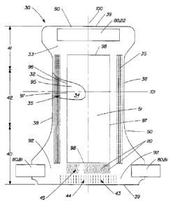
Fig. 2 is an enlarged, fragmentary plan view of the extensible back waist
feature 43 showing the elastic-like zone 44 and the expansive zone 45. In the
embodiment of the present invention shown in Figures 1 and 2, the extensible
back
waist feature comprises a portion of the backsheet. The backsheet 33 is
preferably
a web material constructed of a single layer of polymeric material. The web
material is preferably comprised substantially of linear low density
polyethylene
(LLDPE), although it may also be comprised of other polyolefins such as
polyethylenes including low density polyethylene (LDPE), ultra low density
polyethylene (ULDPE), high density polyethylene (HDPE), or polypropylene
and/or blends thereof and other materials. Examples of other suitable
polymeric
materials include, but are not limited to polyester, polyurethanes,
compostable or
biodegradable polymers, and breathable polymers.
CA 02239425 1998-06-03
WO 97/20531 PCT/US96J18649
14
The extensible back waist feature is shown in Figure 2 in its substantially
untensioned condition. The SELF web ~2 forming the elastic-like zone 44 has
two -
centerlines, a frst centerline 201, (which is also referred to as an axis,
line, or
direction), and a second centerline 200, (which is also referred to as an
axis, line, or
direction), which is generally perpendicular to the first centerline 201.
The SELF web 52 includes a "strainable network" of distinct regions. As
used herein, the term "strainable network" refers to an interconnected and
interrelated group of regions which are able to be extended to some useful
degree in
a predetermined direction providing the SELF web with an elastic-like behavior
in
response to an applied and subsequently released elongation. The strainable
network
includes at least a first region 64 (also generally referred to herein as
bands or
channels) and a second region 66 (also generally referred to herein as ribs).
The
SELF web also includes a transitional region 65 which is at the interface
between the
first region 64 and the second region 66. The transitional region 65 will
exhibit
complex combinations of the behavior of both the first region and the second
region.
It is recognized that every embodiment of the present invention will have a
transitional region, however, preferred embodiments of the present invention
will
exhibit elastic-like behavior substantially as a result of the first region 64
and the
second regions 66. Therefore, the ensuing description of the present invention
will
be concerned with the behavior of the SELF web in the first regions and the
second
regions only and not the complex behavior of the SELF web in the transitional
regions 65.
SELF web 52 has a first surface and a second surface. In the preferred
embodiment shown in Fig. 2, the strainable network includes a plurality of
first
regions 64 and a plurality of second regions 66. The first regions 64 have a
first axis
68 and a second axis 69, wherein the first axis 68 is preferably longer than
the
second axis 69. The first axis 68 of the first region 64 is substantially
parallel to the
first axis 201 of the SELF web 52, while the second axis 69 is substantially
parallel
to the second axis 200 of the SELF web 52. The second regions 66 have a first
axiL
70 and a second axis 71. The first axis 70 is substantially parallel to the
first axis; ,
201 of the SELF web 52, while the second axis 7I is substantially parallel to
the
second axis 200 of the SELF web 52. In the preferred embodiment of Fig. 2, the
first regions 64 and the second regions 66 are substantially linear, extending
continuously in a direction substantially parallel to the first axis of the
SELF web 52.
The f rst region 64 has an elastic modulus E 1 and a cross-sectional area A 1.
CA 02239425 1998-06-03
WO 97/20531 PCT/US96/18649
The second region 66 has a modulus E2 and a cross-sectional area A2.
In the illustrated embodiment, the SELF web 52 has been "formed" such that
the SELF web ~2 exhibits a resistive force along an axis, which in the case of
the
illustrated embodiment is substantially parallel to the first axis 201 of the
SELF web,
when subjected to an applied elongation or axial elongation in a direction
substantially parallel to the first axis 201. As used herein, the term
"formed" refers
to the creation of a desired structure or geometry upon a web material that
will
substantially retain the desired structure or geometry when it is not
subjected to any
externally applied elongations or forces. A SELF web of the present invention
is
comprised of at least a first region and a second region, wherein the first
region is
visually distinct from the second region. As used herein, the term "visually
distinct"
refers to features of the SELF web which are readily discernible to the normal
naked
eye when the SELF web or objects embodying the SELF web are subjected to
normal use. A SELF web of the present invention is comprised of a strainable
network of contiguous, "distinct", and "dissimilar" regions, wherein the
strainable
network includes at least a first region and a second region, where the first
region has
a "surface-pathlength" less than that of the second region, as measured
parallel to a
predetermined axis when the material is in an untensioned state. As used
herein, the
term "formed portion" refers to the portion of the material which is comprised
of the
desired structure or geometry of the strainable network. As used herein the
term
"surface-pathlength" refers to a measurement along the topographic surface of
the
region in question in a direction parallel to a predetermined axis. As used
herein, the
term "distinct" or "dissimilar" when referring to regions, refers to regions
within the
strainable network having measurably different surface-pathlengths as measured
parallel to a predetermined axis while the SELF web is in an untensioned
condition.
The method for determining the surface-pathlength of the respective regions
can be
found in the Test Methods section set forth in subsequent portions of the
present
specification.
in the preferred embodiment shown in Figure 2, the first regions 64 are
substantially planar. That is, the material within the first region 64 is in
substantially
the same condition before and after the formation step undergone by the SELF
web
52. The second regions 66 include a plurality of ribs or rib-like elements 74.
The
rib-like elements 74 may be embossed, debossed or a combination thereof.
The rib-like elements 74 have a first or major axis 76 which is substantially
parallel to the second axis 200 of the SELF web 52, and a second or minor axis
77
CA 02239425 1998-06-03
WO 97!20531 PCT/US96/18649
16
which is substantially parallel to the first axis 201 of the SELF web 52. The
first
axis 76 of the rib-like elements 74 is at Ieast equal to, and preferably
longer than the
second axis 77. Preferably, the ratio of the first axis 76 to the second axis
77 is at
least about 1:1 or greater, and more preferably at least about 2:1 or greater.
The rib-like elements 74 within the second region 66 may be separated from
one another by unformed areas. Preferably, the rib-like elements 74 are
adjacent one
another and are separated by an unformed area of less than 0.10 inches as
measured
perpendicular to the major axis 76 of the rib-like elements 74, and more
preferably,
the rib-like elements 74 are contiguous having no unformed areas between them.
The first region 64 and the second region 66 each have a "projected
pathlength". As used herein the term "projected pathlength" refers to the
length of a
shadow of a region that would be thrown by parallel light. The projected
pathlength
of the first region 64 and the projected pathlength of the second region 66
are equal
to one another. Accordingly, the overall dimension of the SELF web as measured
parallel to the first axis 201 will be substantially the same before and after
formation.
The second region 66 has a surface-pathlength, L2, greater than the surface-
pathlength, L1, of the first region 64 as measured topographically in a
direction
parallel to the first axis of the SELF web while the SELF web is in an
untensioned
condition. Preferably, the surface-pathlength of the second region 66 is at
least
about 15% greater than that of the first region 64, more preferably at least
about 30%
greater than that of the first region, and most preferably at least about 70%
greater
than that of the first region. In general, the greater the surface-pathlength
of the
second region, the greater will be the elongation of the SELF web before
encountering the force wall.
What makes the SELF web particularly well suited for use as the elastic zone
44 of the extensible back waist feature 43 is that it exhibits a modif ed
"Poisson
lateral contraction effect" substantially less than that of an otherwise
identical base
web of similar material composition. As used herein, the term "Poisson lateral
contraction effect" describes the lateral contraction behavior of a material
which is
being subjected to an applied elongation. The method for determining the
Poisson
lateral contraction effect of a material can be found in the Test Methods
section set
forth in subsequent portions of the present specification. Preferably, the
Poisson ,
lateral contraction effect of the SELF web of the present invention is less
than about
0.4 when the web is subjected to about 20% elongation. Preferably, the SELF
web
exhibits a Poisson lateral contraction effect less than about 0.4 when the web
is
CA 02239425 1998-06-03
WO 97/20531 PCT/US96/18649
17
subjected to about 40, 50 or even 60% elongation. More preferably, the Poisson
lateral contraction effect is less than about 0.3 when the SELF web is
subjected to
20, 40, 50 or 60% elongation. The Poisson lateral contraction effect of SELF
webs
' of the present invention is determined by the amount of the web material
which is
occupied by the first and second regions, respectively. As the area of the
SELF web
material occupied by the first region increases, the Poisson lateral
contraction effect
also increases. Conversely, as the area of the SELF web material occupied by
the
second region increases the Poisson lateral contraction effect decreases.
Preferably,
the percent area of the SELF web material occupied by the first area is from
about
2% to about 90%, and more preferably from about 5% to about 50%.
Weh materials of the prior art which have at least one layer of an elastomeric
material will generally have a large Poisson lateral contraction effect, i.e.,
they will
"neck down" as they elongate in response to an applied force. SELF webs of the
present invention can be designed to reduce if not substantially eliminate the
Poisson
lateral contraction effect of film based elastomeric webs of the prior art.
For SELF web material 52, the direction of applied axial elongation, D,
indicated by arrows 80 in Figure 2, is substantially perpendicular to the f
rst axis 76
of the rib-like elements 74. As the rib-like elements 74 are able to unbend or
geometrically deform in a direction substantially perpendicular to their first
axis 76,
the direction of applied elongation to cause extension in the SELF web 52 is
also
substantially perpendicular to the first axis 76 of the rib-like elements 74.
In Figure 3 there is shown a graph of the resistive force-elongation curve 720
of a formed polymeric SELF web material along with a curve 710 for a base film
of
similar composition. Specifically the samples are polymeric web materials,
comprised substantially of linear low density polyethylene, approximately
0.001"
thick, designated sample 1401 available from Clopay, Cincinnati Ohio. The
method
for generating the resistive force-elongation curves can be found in the Test
Methods
section set forth in subsequent portions of the present specification.
Referring now
to the force-elongation curve 720, there is an initial substantially linear,
lower force
versus elongation stage I designated 720a, a transition zone designated 720b
which
indicates the encounter of the force wall, and a substantially linear stage II
designated 720c which displays substantially higher force versus elongation
behavior.
As seen in Figure 3 the SELF web exhibits different elongation behavior in
the two stages when subjected to an applied elongation in a direction parallel
to the
CA 02239425 1998-06-03
WO 97/20531 PCT/US96/18649
18
first axis of the SELF web. The resistive force to the applied elongation is
significantly different between stage I (720a) and stage II (720c) of cure 720
as '
compared to curve 710 which does not exhibit this behavior. As seen in Figure
3.
the SELF web exhibits different elongation behavior in the two stages when '
subjected to an applied elongation in a direction parallel to the first axis
of the SELF
web. The resistive force exerted by the SELF web to the applied elongation is
significantly less in the stage I region (720a) versus the stage II region
(720c) of
curve 720. Furthermore, the resistive force exerted by the SELF web to the
applied
elongation as depicted in stage I (720a) of curve 720 is significantly less
than the
resistive force exerted by the base web as depicted in curve 710 within the
limits of
elongation of stage I. As the SELF web is subjected to further applied
elongation
and enters stage II (720c) the resistive force exerted by the SELF web
increases and
approaches the resistive force exerted by the base web. The resistive force to
the
applied elongation for the stage I region (720a) of the SELF web is provided
by the
molecular-level deformation of the first region of the SELF web and the
geometric
deformation of the second region of the SELF web. This is in contrast to the
resistive
force to an applied elongation that is provided by the base web, depicted in
curve
710, which results from molecular-level deformation of the entire web. SELF
web
materials can be designed to yield virtually any resistive force in stage I
which is less
than that of the base web material by adjusting the percentage of the web
surface
which is comprised of the first and second regions, respectively. The force-
elongation behavior of stage I can be controlled by adjusting the width, cross-
sectional area, and spacing of the first region and the composition of the
base web.
Referring now to Figures 4A-4C, as SELF web 52 is subjected to an applied
axial elongation, D, indicated by arrows 80, the first region 64 having the
shorter
surface-pathlength, L1, provides most of the initial resistive force, P1, as a
result of
molecular-level deformation, to the applied elongation which corresponds to
stage I.
While in stage I, the rib-Iike elements 74 in the second region 66 are
experiencing
geometric deformation, or unbending and offer minimal resistance to the
applied
elongation. In the transition zone (720b) between stages i and II, the rib-
like ,
elements 74 are becoming aligned with the applied elongation. That is, the
second
region is exhibiting a change from geometric deformation to molecular-level
deformation. This is the onset of the force wall. In stage II, as seen in
Figure 4C.
the rib-like elements 74 in the second region 66 have become substantially
aligned
with the plane of applied elongation ( i.e. the second region has reached its
Iimit of
CA 02239425 1998-06-03
WO 97/20531 PCT/US96/I$649
I9
geometric deformation) and begin to resist further elongation via molecular-
level
deformation. The second region 66 now contributes, as a result of molecular-
level
deformation, a second resistive force, P2, to further applied elongation. The
resistive
forces to elongation depicted in stage II by both the molecular-level
deformation of
the first region 64 and the molecular-level deformation of the second region
66
provide a total resistive force, PT, which is greater than the resistive force
depicted
in stage I which is provided by the molecular-level deformation of the first
region 64
and the geometric deformation of the second region 66. Accordingly, the slope
of
the force-elongation curve in stage II is significantly greater than the slope
of the
force-elongation curve in stage I.
The resistive force P 1 is substantially greater than the resistive force P2
when
(L 1 + D) is less than L2. When (L I + D) is less than L2 the first region
provides the
initial resistive force Pl, generally satisfying the equation:
Pl = (AI x EI x D)
LI
When (L I + D) is greater than L2 the first and second regions provide a
combined
total resistive force PT to the applied elongation, D, generally satisfying
the
equation:
PT=(Al xEl xD,~ + ~A2xE2x1L1 +D-L2I~
Ll L2
The maximum elongation occurring while in stage I is the "available stretch"
of the SELF web. The available stretch corresponds to the distance over which
the
second region experiences geometric deformation. The available stretch can be
effectively determined by inspection of the force-elongation curve 720 as
shown in
Fig. 3. The approximate point at which there is an inflection in the
transition zone
between stage I and stage II is the percent elongation point of "available
stretch".
The range of available stretch can be varied from about 10% to 100% or more;
this
range of elongation is often found to be of interest in disposable absorbent
articles.
and can be largely controlled by the extent to which the surface-pathlength L2
in the
second region exceeds the surface-pathlength L I in the first region and the
properties
(composition) of the base film. The terns available stretch is not intended to
imply a
CA 02239425 1998-06-03
WO 97/20531 PCT/US96/18649
limit to the elongation which the SELF web may be subjected to as there are
applications where elongation beyond the available stretch is desirable.
Significantly
higher forces are required to achieve percent elongations in the base film
equivalent
to those percent elongations in the SELF web. The approximate extent of stage
I can
be controlled as desired by adjusting the pathlengths, L 1 and L2, in an
untensioned
condition. The force-elongation behavior of stage I can be controlled by
adjusting
the width, thickness, and spacing of first region 64 and the properties of the
base
film.
The curves 730 and 735 in Figure 5 depict the elastic hysteresis behavior
exhibited by the SELF web. The sample is the same as used to produce the graph
in
Figure 3 (Clopay 1401 ). The sample was examined for elastic hysteresis
behavior at
an elongation of 60%. Curve 730 represents the response to an applied and
released
elongation during the first cycle and curve 735 represent the response to an
applied
and released elongation during the second cycle. The force relaxation during
the
first cycle 731 and the percent set 732 are depicted in Figure 5. Note that
significant
recoverable elongation, or useful elasticity, is exhibited at relatively low
forces over
multiple cycles. i.e., this means the SELF web can easily expand and contract
to a
considerable degree. The method for generating the elastic hysteresis behavior
can
be found in the Test Method section set forth in subsequent portion of the
present
specification.
When the SELF web is subjected to an applied elongation, the SELF web
exhibits an elastic-like behavior as it extends in the direction of applied
elongation
and returns to its substantially untensioned condition once the applied
elongation or
force is removed, unless extended beyond the point of yielding. The SELF web
is
able to undergo multiple cycles of appred elongation without losing its
ability to
substantially recover. Accordingly, the SELF web is able to return to its
substantially untensioned condition once the applied elongation is removed.
While the SELF web may be easily and reversibly extended in the direction
of applied axial elongation, in a direction substantially perpendicular to the
first axis
76 of the rib-like elements, the SELF web is not as easily extended in a
direction
substantially parallel to the first axis of the rib-like elements. The
formation of the
rib-like elements allows the rib-like elements to geometrically deform in a
direction
substantially perpendicular to the first or major axis of the rib-like
elements. while
requiring substantially molecular-level deformation to extend in a direction
substantially parallel to the first axis of the rib-like elements.
CA 02239425 1998-06-03
WO 97/20,531 PCT/US96/18649
21
The amount of applied force required to extend the SELF web is dependent
upon the composition and thickness of the base material forming the SELF web
and
the width and spacing of the first regions, with narrower and more widely
spaced
first regions requiring lower applied extensional forces to achieve the
desired
elongation for a given composition and thickness. The first axis 68, (i.e.,
the length)
of the undeformed first regions is preferably greater than the second axis 69,
(i.e., the
width) with a preferred length to width ratio of about 5: I or greater.
The depth and number of rib-like elements 74 can also be varied to control
the extension force and available stretch of the SELF web. The available
stretch or
elongation is increased if for a given number of rib-like elements, the height
or
degree of formation imparted on the rib-like elements is increased. Similarly,
the
available stretch is increased if for a given height or degree of formation.
the number
or frequency of the rib-like elements is increased.
There are several functional properties that can be controlled through the
application of the present invention. There is the resistive force exerted by
the SELF
web against an applied elongation and the available stretch of the SELF web
before
the force wall is encountered. The resistive force that is exerted by the SELF
web
against an applied elongation is a function of the material (e.g.,
composition,
molecular structure and orientation, etc.) and thickness and the percent of
the
projected surface area of the SELF web that is occupied by the first region.
The
higher the percent area coverage of the SELF web by the first region, the
higher the
resistive force that the SELF web will exert against an applied elongation for
a given
material composition and thickness. The percent coverage of the SELF web by
the
first region is determined in part if not wholly by the width of the first
region and the
spacing between adjacent first regions.
The available stretch of the SELF web is determined by the surface-
pathlength of the second region. This is determined at least in part by the
rib-like
elements spacing, rib-like element frequency and depth of formation of the rib-
like
elements as measured perpendicular to the plane of the SELF web. In general,
the
greater the surface-pathlength of the second region the greater the available
stretch of
the SELF web.
While an entire SELF web may include a strainable network of first and
second regions, the present invention may also be practiced by providing only
specific portions of the SELF web with a strainable network comprised of first
and
second regions.
CA 02239425 1998-06-03
WO 97/20531 PCT/US96/18649
22
The configuration and spacing of the first and second regions may also be
varied to vary the characteristics of the SELF web. For example, the second
regions
may comprise curvilinear rib-like elements, or the first regions and the
second
regions may be curvilinear. The SELF web may also exhibit an elastic-like
behavior
along a plurality of axes by extending the axes in a radial, fan-like array to
allow the
SELF web to exhibit an elastic-like behavior along a plurality of axes. For
example,
the multiple axes may be positioned at various angles to one another such as
4~°, 90°
135°, etc. In addition to the various angles of orientation, the
regions themselves
may be straight, curvilinear, or combinations thereof. The surface-pathlengths
in the
second region may also provide a difference in amplitude of t~e rib-like
elements
such that the SELF web will have different zones of availabl stretch. It is
also
possible that the rib-like elements can be varied between adjacent regions to
provide
different available stretches in the adjacent second regions. The widths of
the first
region may also vary across the web with the narrower regions offering a lower
resistive force to an applied elongation as compared to the higher resistive
force
offered by the wider first region.
The SELF web also need not be extensible only in the direction parallel to
the lateral centerline 101 of the diaper 30 as shown in Figure 1. For example,
the
first axis and the second axis of the SELF web may be disposed at an angle to
the
longitudinal centerline and lateral centerline of the diaper 30, respectively.
Thus, the
SELF web would axially elongate along a line at an angle to the lateral
centerline of
the diaper. This angle is preferably between about 0° and about
30° for the diapers
of the present invention. Further, portions of the SELF web may have different
angles of extensibility.
Referring to Figure 2, the expansive zone 45, and the elastic-like zone 44
meet at a common border 120. In the embodiment shown in Fig. 2, the border 120
is
substantially parallel to the axis of expansion and contraction, axis 201. The
expansive zone 45 includes a plurality of incrementally stretched regions I
10. The
incrementally stretched regions 110 are formed by subjecting the expansive
zone 45
to mechanical stretching such as an incremental stretching system as will be ,
described in greater detail hereinafter.
The incrementally stretched regions 110 have been stretched, strained, or ,
elongated in a direction parallel to the first axis 201 of the SELF web 52.
The
incremental stretching of regions 110 of expansive zone 45 allow the expansive
zone
to effectively elongate (yield) when the elastic-like zone 44 is extended,
without
CA 02239425 1998-06-03
WO 97/20531 PCTJUS96/18649
23
generating any excessive tensional forces. The expansive zone 45 has a surface-
pathlength greater than the surface-pathlength of the first region 64 of the
SELF web
52 of the elastic-like zone 44 as measured in a direction parallel to the
first a~cis 201
of the SELF web 52 while both zones are in an untensioned condition. In
addition,
the expansive zone 45 has a surface-pathlength different ,than the surface-
pathlength
of the second region 66 of the SELF web 52 of the elastic-like zone 44 as
measured
in a direction parallel to the first axis 201 of the SELF web 52 while both
zones are
in an untensioned condition.
As the extensible waist feature 43 is subjected to an applied axial elongation
indicated by arrows 80, the expansive zone 45 provides a relatively low
resistive
force to the applied elongation as the expansive zone 45 undergoes
substantially
geometric deformation. The incrementally stretched regions I I O initially
experience
geometric deformation or unbending and offer minimal resistance to the applied
elongation. As elongation continues the incrementally stretched regions 110
become
substantially aligned with the plane of elongation (the incrementally
stretched
regions 110 have reached their limit of geometric deformation) and they begin
to
resist further elongation via molecular-level deformation. The expansive zone
45
now contributes a higher resistive force as a result of this molecular-level
deformation. The amount or extent of geometric deformation that the expansive
zone will undergo before experiencing molecular-level deformation is dependent
at
least to some degree upon the amount of pre-straining or stretching that is
imparted
upon the expansive zone.
If the expansive zone 45 has a surface-pathlength greater than the surface-
pathlength of the second region 66, the second region 66 will first begin to
contribute
a significant resistive force before the expansive zone 45 contributes a
significant
resistive force. Alternatively, if the expansive zone 45 has a surface-
pathlength less
than the surface-pathlength of the second region 66, the expansive zone 4~
will be
the first to contribute a significant resistive force.
Preferably, the expansive zone 45 must be free of restrictions to expansion
for a certain distance from the elastic-like zone 44 which distance is
indicated as 121
in Fig. 2, to permit the elastic-like zone 44 to elastically expand and
contract within
its designed limits. Examples of restrictions to expansion are bonding the
expansive
zone 45 to a non-expansive member such as an absorbent core, a tape fastening
member, or a topsheet. It should be recognized by those skilled in the art
that
distance 12I will depend on the desired amount of elastic expansion and
contraction
CA 02239425 1998-06-03
WO 97/20531 PCT/US96118649
24
in elastic-like zone 44, the surface-pathlength of expansive zone 45 and the
nature of
the potential restriction of movement.
Referring now to Figure 6, there is shown an apparatus generally indicated as
500 for forming the extensible back waist feature 43 comprising both the
elastic-like
zone 44 and the expansive zone 4S, where the elastic-like zone 44 comprises a
SELF
web and the expansive zone comprises a prestrained web comprising
incrementally
stretched regions. Apparatus 500 employs opposed pressure applicators having
three-dimensional surfaces which at least to a degree are complimentary to one
another. Apparatus 500 comprises a pair of intermeshing rolls 502 and 520.
Roll
502 includes a plurality of first corrugated or toothed regions 506, a
plurality of
second corrugated or toothed regions 509, and a plurality of grooved regions
512.
Grooved regions 512 extend in a direction substantially parallel to a
longitudinal axis
running through the center of cylindrical roll 502. In the embodiment shown in
Figure 6, roll 502 includes three grooved regions 512. However, roll 502 may
include any number of grooved regions S 12. Toothed region 506 which are
located
between grooved regions 512, include a plurality of teeth 507. Toothed regions
509
include a plurality of teeth 510. RoII 520 includes a plurality of teeth 522
which
mesh with teeth 507 and 510 of roll 502.
As a web, such as a backsheet 33 of disposable diaper 30, is directed through
apparatus S00 between intermeshing rolls S02 and 520, the portion of the web
passing between toothed regions 509 containing teeth 510, and teeth 522 on
roll 520
will be incrementally stretched forming incrementally stretched regions which
correspond to incrementally stretched regions 110 in the expansive zone 45,
shown
in Figure 2. The portion of the web passing between grooved regions 512 and
teeth
522 on roll 520 will remain unformed, thus providing unformed regions in the
web
which correspond to the first regions 64 of the SELF web 52 shown in Figure 2.
The
portions of the web passing between toothed regions 506 containing teeth 507
and
teeth S22 on roll 520 will be incrementally stretched forming rib-like
elements in the
web which correspond to rib-like elements 74 in the second regions 66 of the
SELF
web 52 shown in Figure 2.
The exact configuration, spacing and depth of the teeth on the rolls 502 and
520 may be varied depending on the amount of incremental stretching desired.
The
degree of overlap of the teeth on rolls 502 and 520 may also be adjusted, as
desired,
to produce more or less incremental stretching.
While the extensible waist feature comprising the elastic-like zone and the
CA 02239425 1998-06-03
WO 97/20531 PCT/US96118649
expansive zone has been described as a single layer of polymeric material, the
' present invention may be practiced equally well with other materials or with
laminates of two or more materials. Examples of suitable materials include two
dimensional apertured films, macroscopically expanded, three-dimensional,
apertured formed films. Examples of other suitable materials include composite
structures or laminates of polymer films, and nonwovens. Laminates of polymer
films and nonwovens may also comprise absorbent or fibrous absorbent
materials,
foams, or other compositions. Examples of such laminates include a nonwoven
topsheet and a polymeric film backsheet found on commercially available
disposable
diapers. Additional reinforcing elements can also be added for strength and
recovery
. benefits.
The expansive zone and the elastic-like zone may also be used on other
portions of the diaper. For example, the expansive zone and the elastic-like
zone
may be used to form the elasticized leg cuffs 35, the front waist feature 90,
or the ear
flaps 92. In addition, the expansive zone and the elastic-like zone may be
used to
form other extensible portions on the diaper.
The present invention is intended to produce a functional equivalent to a
conventional diaper having an elastic member secured to diapers to provide
contractive and expansive properties. Conventional diapers are made by bonding
an
elastic member in a tensioned state to the topsheet and backsheet in the waist
area.
After bonding, the tension is released causing gathers to form in the waist.
By use of
the elastic-like and expansive zones of the present invention, the same result
is
accomplished without the addition of an elastic member.
Referring now to Fig. 7 there is shown a plan view of another embodiment of
a diaper 130 of the present invention: Diaper 130 comprises a backsheet 133
comprising an extensible back waist feature 143 and an extensible front waist
feature
147, a topsheet and a backsheet, (for simplification the topsheet and
backsheet are
not shown in Fig. 7). Back waist feature 143 comprises an elastic-like zone
144 and
an expansive zone 145. Front waist feature 147 comprises an elastic-like zone
146
and an expansive zone 145. In this embodiment the axis of elastic contraction
and
expansion in the elastic-like zones and the direction of expansion in the
expansive
zone are parallel to each other and also to the transverse axis 10 i .
The expansive zone 145 will cover part, or preferably, all of the width and
length of the underlying absorbent core of the diaper which is added in a
later step in
the assembly. The width, length and amount of expansion of the expansive zone
145
CA 02239425 1998-06-03
WO 97/20531 PCT/US96/18649
26
can be adjusted to provide the desired properties. The unexpended width of the
expansion zone I4S, (as measured in a direction parallel to the transverse
axis 1 O I ),
can be larger, smaller, or the same as the unexpended width of the elastic-
like zones
144 and 146. However, only the portion of elastic-like zone which has a common
boundary with the expansive zone will behave contractively in the firiished
product
to produce a gathered waist feature. The unexpended width of the expansive
zone
I4S is shown in Figure 7 as being equal to the unexpended width of the elastic-
like
zones 144 and 146 which maximizes the amount the elastic-like zones contract
relative to the expansive zone 145.
The surface-pathlength of the expansive zone I4S determines the amount of
relative "contraction" of the elastic-like zones. For example, if the surface-
pathlength of the expansive zone is 40% longer than the elastic-like zone, the
elastic-
like zone has the potential to exhibit 40% contracted stretch in the finished
product.
In Figure 8 the diaper 130 is stretched in the direction indicated by arrows
1 SO to fully extend the expansive zone 14S and to put the elastic-like zones
144 and
146 under tension. Similar to distance 121 in Fig. 2., distance I S 1 between
lines I S2
and IS3 of Fig. 8, represents the minimal distances the expansive zone must
extend
uninhibited, e.g., unbonded to another layer such as an absorbent core, from
the
elastic-like zone to produce the elastically expansive and contractive
behavior. Line
1 S2 represents the common border between the two zones. Line 1 S3 can
represent
the waist edge of the absorbent core or it can represent the topmost extent of
the
bond between the core and the backsheet. The distance 1 S 1 must be determined
so
that the elastic-like zone can contract without hindrance to its unstrained
length when
the tension is removed.
Although Figure 8 indicates a single uniform expansive zone having the same
width as the elastic-like zones, it should be understood that as long as the
requirement for unhindered motion is met between lines 1 S2 and 1 S3, the
remainder
of the expansive zone could have multiple regions with different widths and
surface-
pathlengths.
Referring now to Fig. 9, there is shown a plan view of another embodiment
of a diaper 160 of the present invention. Diaper 160 comprises a backsheet 161
comprising an extensible back waist feature 162 comprising an elastic-like
zone 164
and an expansive zone 166. The width of the expansive zone 164, (as measured
in a
direction parallel to the transverse centerline 101 ), is greater than the
width of the
adjacent expansive zone 166. The expansive zone 166 may extend to the
CA 02239425 1998-06-03
WO 97/20531 PCT/US96/18649
77
longitudinal edge of the diaper.
To make a diaper of the present invention, the backsheet is first provided
with the desired arrangement of elastic-like and expansive zones. The
backsheet is
' then tentered or extended to expand the expansive zone. An absorbent core is
then
bonded to the expansive zone while the expansive zone is in its expanded
condition
by any suitable means, for example, thin spirals of glue. A suitable topsheet
is then
bonded to the absorbent core and backsheet. The topsheet is sized
substantially the
same as the backsheet. Once the tension is removed, the elastic-like zones
will
contract causing the elastic-like zones to neck down and gather.
Alternatively, the diaper may be made by first providing the backsheet with
one or more expansive zones. The expansive zones are then expanded and secured
to another substrate such as an absorbent core. A topsheet is then secured to
the
backsheet and absorbent core. The elastic-like zones are then formed in both
the
topsheet and the backsheet.
Other suitable methods may also be used to manufacture the diaper of the
present invention. In addition, the order of steps may be also be changed.
Furthermore, some steps may also be combined with other steps.
Referring again to Fig. 8, the bonding of the backsheet to the absorbent core
becomes very important. The absorbent core may have any length, for example,
the
absorbent core may extend substantially along the entire length of the diaper.
However, line 153 in Fig. 8, represents the uppermost limit of bonding between
the
core and the backsheet. As seen in Fig. 8, line 153 is completely within
expansive
zone 145. If line 153 is located within the elastic-like zone, it will
significantly
inhibit the contractive and expansive properties of the elastic-like zone,
thus
significantly eliminating the benefits of the expansive zone, i.e., the
removal of the
line of tension. It should be noted that a portion of the elastic-like zone
may be
bonded to the absorbent core to keep the absorbent core from floating.
Preferably,
such bonding will be at or near centerline i 00 where the amount of expansion
and
contraction of the elastic-like zone is at a minimum.
Test Methods
Surface-Pathlength
Pathlength measurements of formed material regions are to be determined by
selecting and preparing representative samples of each distinct region and
analyzing
CA 02239425 1998-06-03
WO 97/20531 PCT/US96/18649
28
these samples by means of microscopic image analysis methods.
Samples are to be selected so as to be representative of each region's surface
geometry. Generally, the transition regions should be avoided since they would
normally contain features of both the f rst and second regions. The sample to
be
measured is cut and separated from the region of interest. The "measured edge"
is to
be cut parallel to a specified axis of elongation. Usually this axis is
parallel to the
formed primary-axis of either the first region or the second region. An
unstrained
sample length of one-half inch is to be "gauge marked" perpendicular to the
"measured edge": while attached to the web material, and then accurately cut
and
removed from the web material.
Measurement samples are then mounted onto the long-edge of a microscopic
glass slide. The "measured edge" is to extend slightly (approximately 1 mm)
outward from the slide edge. A thin layer of pressure-sensitive adhesive is
applied to
the glass face-edge to provide a suitable sample support means. For highly
formed
sample regions it has been found desirable to gently extend the sample in its
axial
direction (without imposing significant force) simultaneous to facilitate
contact and
attachment of the sample to the slide-edge. This allows improved edge
identification
during image analysis and avoids possible "crumpled" edge portions that
require
additional interpretation analysis.
Images of each sample are to be obtained as "measured edge" views taken
with the support slide "edge on" using suitable microscopic measuring means of
sufficient quality and magnification. Fig. 38 shows a typical view of a
portion of the
second region of a sample 900 having a first side edge 901 and a second side
edge
902 used to determine the surface-pathlength. Data herein presented was
obtained
using the following equipment; Keyen~e VH-6100 (20x Lens) video unit, with
video-image prints made with a Sony Video printer Mavigraph unit. Video prints
were image-scanned with a Hewlett Packard ScanJet iIP scanner. Image analysis
was on a Macintosh IICi computer utilizing the software NIH MAC Image version
1.45.
Using this equipment, a calibration image initially taken of a grid scale
length
of .500" with .005" increment-marks to be used for calibration setting of the
computer image analysis program. All samples to be measured are then video-
imaged and video-image printed. Next, all video-prints are image-scanned at
100
dpi (256-level gray scale) into a suitable Mac image-f le format. Finally,
each
image-file {including calibration file) is analyzed utilizing Mac Image 1.45
computer
CA 02239425 1998-06-03
WO 97/20531 PCTlCTS96/18649
29
program. All samples are measured with freehand line-measurement tool
selected.
' Samples are measured on both side-edges and the lengths are recorded. Simple
film-
like (thin & constant thickness) samples require only one side-edge to be
measured.
' Laminate and thick foam samples are measured on both side-edges. Length
measurement tracings are to be made along the full gauge length of a cut
sample. In
cases of highly deformed samples, multiple (partially overlapping) images may
be
required to cover the entire cut sample. In these cases, select characteristic
features
common to both overlapping-images and utilize as "markers" to permit image
length
readings to adjoin but not overlap.
The final, determination of surface-pathlength for each region is obtained by
averaging the lengths of five (5) separate 1/2" gauge-samples of each region.
Each
gauge-sample "surface-pathlength" is to be the average of both side-edge
surface-
pathlengths.
While the test method described above is useful for many of the web
materials of the present invention it is recognized that the test method may
have to
be modified to accommodate some of the more complex web materials within the
scope of the present invention.
Poisson's Lateral Contraction Effect
The Poisson's lateral contraction effect is measured on an Instron Model
1122, as available from Instron Corporation of Canton, Massachusetts, which is
interfaced to a Gateway 2000 486/33Hz computer available from Gateway 2000 of
N. Sioux City, South Dakota, using Test WorksT"" software which is available
from
Sintech, Inc. of Research Triangle Park, North Carolina. All essential
parameters
needed for testing are input in the T-estWorksT"" software for each test. Data
collection is accomplished through a combination of manual sample width
measurements, and elongation measurements made within TestWorksT"".
The samples used for this test are 1" wide x 4" long with the long axis of the
sample cut parallel to the direction of the first region of the sample. The
sample
should be cut with a sharp knife or suitably sharp cutting device designed to
cut a
precise 1 " wide sample. It is important that a "representative sample" should
be cut
so that an area representative of the symmetry of the overall pattern of the
deformed
region is represented. There will be cases (due to variations in either the
size of the
deformed portion or the relative geometries of regions 1 and 2) in which it
will be
necessary to cut either larger or smaller samples than is suggested herein. In
this
CA 02239425 1998-06-03
WO 97/20531 PCT/US96/18649
case, it is very important to note (along with any data reported) the size of
the
sample, which area of the deformed region it was taken from and preferably
include
a schematic of the representative area used for the sample. In general, an
"aspect
ratio" of (2:I) for the actual extended tensile portion (ll:wl) is to be
maintained if
possible. Five samples are tested.
The grips of the Instron consist of air actuated grips designed to concentrate
the entire gripping force along a single line perpendicular to the direction
of testing
elongation having one flat surface and an opposing face from which protrudes a
half
round. No slippage should be permitted between the sample and the grips. The
distance between the lines of gripping force should be 2" as measured by a
steel rule
held beside the grips. This distance will be referred to from here on as the
"gauge
length".
The sample is mounted in the grips with its long axis perpendicular to the
direction of applied elongation. An area ,representative of the overall
pattern
geometry should be symmetrically centered between the grips. The crosshead
speed
is set to 10 in/min. The crosshead moves to the specified strain (measurements
are
made at both 20 and 60% elongation}. The width of the sample at its narrowest
point
(w2) is measured to the nearest 0.02" using a steel rule. The elongation in
the
direction of applied extension is recorded to the nearest 0.02" on the
TestWorks
software. The Poisson's Lateral Contraction Effect (PLCE) is calculated using
the
following formula:
PLCE = w2 - wl
wl
12-11
11
where w2 = The width of the sample under an applied longitudinal
elongation;
wi = The original width of the sample;
12 = The length of the sample under an applied longitudinal
elongation; and
i 1 = The original length of the sample (gauge length);
Measurements are made at both 20 and 60% elongation using five different
samples for each given elongation. The PLCE at a given percent elongation is
the
CA 02239425 1998-06-03
WO 97/20531 PCT/LTS96/I8649
3I
average of five measurements.
While the test method described above is useful for many of the web
materials of the present invention it is recognized that the test method may
have to
be modified to accommodate some of the more complex web materials within the
scope of the present invention.
Hysteresis Test
The hysteresis test is used for measuring the percent set and percent force
relaxation of a material. The tests are performed on an Instron Model II22,
available from Instron Corporation of Canton, Mass. which is interfaced to a
Gateway 2000 486/33Hz computer available from Gateway 2000 of N. Sioux City,
South Dakota 57049, using TestWorksT"" software which is available from
Sintech,
Inc. of Research Triangle Park, North Carolina 27709. All essential parameters
needed for testing are input in the TestWorksr"" software for each test (i.e.
Crosshead
Speed, Maximum percent elongation Point and Hold Times). Also, aII data
collection, data. analysis and graphing are done using the TestWorksT""
software.
The samples used for this test are 1" wide x 4" long with the long axis of the
sample cut parallel to the direction of maximum extensibility of the sample.
The
sample should be cut with a sharp exacto knife or some suitably sharp cutting
device
design to cut a precise 1" wide sample. (If there is more than one direction
of
elongation of the material, samples should be taken parallel to representative
directions of elongation). The sample should be cut so that an area
representative of
the symmetry of the overall pattern of the deformed region is represented.
There
will be cases (due to variations in either the size of the deformed portion or
the
relative geometries of the first and second regions) in which it will be
necessary to
cut either larger or smaller samples than is suggested herein. In this case,
it is very
important to note (along with any data reported) the size of the sample, which
area of
the deformed region it was taken from and preferably include a schematic of
the
representative area used for the sample. Three separate tests at 20, 60 and
I00%
strain are typically measured for each material. Three samples of a given
material
are tested at each percent elongation.
The grips of the Instron consist of air actuated grips designed to concentrate
the entire gripping force along a single line perpendicular to the direction
of testing
stress having one flat surface and an opposing face from which protrudes a
half
round to minimize slippage of the sample. The distance between the lines of
CA 02239425 1998-06-03
WO 97/20531 PCT/US96/18649
32
gripping force should be 2" as measured by a steel rule held beside the grips.
This
distance will be referred to from hereon as the "gauge length". The sample is
mounted in the grips with its long axis perpendicular to the direction of
applied
percent elongation. The crosshead speed is set to 10 in/min. The crosshead
moves
to the specified maximum percent elongation and holds the sample at this
percent
elongation for 30 seconds. After the thirty seconds the crosshead returns to
its
original position {0% elongation) and remains in this position for 60 seconds.
The
crosshead then returns to the same maximum percent elongation as was used in
the
first cycle, holds fox thirty seconds and then again returns to zero.
A graph of two cycles is generated. A representative graph is shown in Fig.
7. The percent force relaxation is determined by the following calculation of
the
force data from the first cycle:
Force at Max. % elongation - Force after 30 sec. hold x I00 = % Force
Relaxation
Force at Maximum % elongation (cycle 1 )
The percent set is the percent elongation of the sample of the second cycle
where the
sample starts to resist the elongation. The percent set and the percent force
relaxation are shown graphically also in Figs. 7, 9, 11, 13 and 15. The
average
percent force relaxation and percent set for three samples is reported for
each
maximum percent elongation value tested.
While the test method described above is useful for many of the web
materials of the present invention it is recognized that the test method may
have to
be modified to accommodate some of the more complex web materials within the
scope of the present invention.
Tensile Test
The tensile test is used for measuring force versus percent elongation
properties and percent available stretch of a material. The tests are
performed on an
Instron Model 1122, available from Instron Corporation of Canton, Mass. which
is
interfaced to a Gateway 2000 486/33Hz computer available from Gateway 2000 of
N. Sioux City, South Dakota , using TestWorksr"" software which is available
from
Sintech, Inc. of Research Triangle Park, North Carolina. All essential
parameters
needed for testing are input in the TestWorksT"" software for each test. Also,
all data
collection, data analysis and graphing are done using the TestWorksT""
software.
CA 02239425 1998-06-03
WO 97/20531 PCT/U596/18649
33
The samples used for this test are 1 " wide x 4" long with the long axis of
the
sample cut parallel to the direction of maximum extensibility of the sample.
The
sample should be cut with a sharp exacto knife or soma suitably sharp cutting
device
design to cut a precise I " wide sample. (If there is more than one direction
of
extensibility of the material, samples should be taken parallel to
representative
direction of elongation). The sample should be cut so that an area
representative of
the symmetry of the overall pattern of the deformed region is represented.
There
will be cases (due to variations in either the size of the deformed portion or
the
relative geometries of regions 1 and 2) in which it will be necessary to cut
either
larger or smaller samples than is suggested herein. In this case, ~t is very
important
to note (along with any data reported) the size of the sample,~J which area of
the
deformed region it was taken from and preferably include a schematic of the
representative area used for the sample. Three samples of a given material are
tested.
The grips of the Instron consist of air actuated grips designed to concentrate
the entire gripping force along a single line perpendicular to the direction
of testing
stress having one flat surface and an opposing face from which protrudes a
half
round to minimize slippage of the sample. The distance between the lines of
gripping force should be 2" as measured by a steel rule held beside the grips.
This
distance will be referred to from hereon as the "gauge length". The sample is
mounted in the grips with its Iong axis perpendicular to the direction of
applied
percent elongation. The crosshead speed is set to i 0 in/min. The crosshead
elongates the sample until the sample breaks at which point the crosshead
stops and
returns to its original position (0 % elongation).
Graphs of the tensile data. are shown in Figs. 6, 8, I 0, I2 and 14. The
percent
available stretch is the point at which there is an inflection in the force -
elongation
curve, beyond which point there is a rapid increase in the amount of force
required to
elongate the sample further. This point is shown graphically in Figs. 6, 8,
10, 12 and
I4. The average of the percent available stretch for three samples is
recorded.
While the test method described above is useful for many of the web
materials of the present invention it is recognized that the test method may
have to
be modified to accommodate some of the more complex web materials within the
scope of the present invention.
While particular embodiments of the present invention have been illustrated
and described, it would be obvious to those skilled in the art that various
other
CA 02239425 1998-06-03
WO 97!20531 PCTJUS96/I8649
34
changes and modifications can be made without departing from the spirit and
scope
of the invention. It is therefore intended to cover in the appended claims all
such
changes and modifications that are within the scope of this invention.