Note: Descriptions are shown in the official language in which they were submitted.
CA 02239516 1998-06-03
WO 97/20533 PCTNS96118946
1
ABSORBENT ARTICLE WITH ANGLED BAND STRUCTURAL
ELASTIC LIKE FILM CUFFS
FTELD OF THE INVENTION
This invention relates to disposable absorbent articles such as sanitary
napkins,
incontinent devices, and the like. More particularly, this invention is
directed to a
sanitary napkin having cuffs for preventing lateral flow of bodily fluids,
such as
menses.
BACKGROUND OF THE INVENTION
As is well known, a disposable absorbent article, such as a sanitary napkin,
has
a liquid pervious topsheet, a liquid impervious backsheet, and an absorbent
core
disposed between the topsheet and the backsheet. Such an absorbent article
should
conform to the wearer's urogenital region, and be able to prevent leakage of
body
fluids, particularly in the lateral direction. One means of reducing leakage
and
conforming to a wearer's urogenital region is to provide for the absorbent
article to
be cup-shaped during use. Such absorbent articles can be further provided with
cuffs
to provide a barrier for reduction of lateral leakage of bodily fluids.
Such approaches are known to the art. For example, one means for making the
absorbent article cup-shaped and forming cull's, as stated above, is to shape
the
topsheet, the core and the backsheet themselves such that the absorbent
article takes
the cup-like form, and the topsheet and/or the backsheet forms the cuffs on
both
sides of the longitudinally central portion of the absorbent article. Such
formed
absorbent articles are described in U.S. Patent 3,575,174, U.S. Patent
4,678,527,
and U.S. Patent 4,834,739. Absorbent articles of this type have problems such
as: 1)
increased manufacturing cost because the topsheet, the core and the backsheet
have
to be shaped to a required form and (2) the free end of the cuff contacts the
wearer's
skin and may cause wearer discomfort when such an absorbent article is worn
because the portion comprising the cuff has no stretch properties.
A second approach to making an absorbent article cup-shaped and forming the
cuffs is to join band-like elastic pieces, in an elastically elongated state,
to the
topsheet and/or the backsheet adjacent both longitudinal edges of the
absorbent
article. The use of a rubber strip or a thermoplastic elastomeric strip as the
band-like
elastic piece has been proposed. Such absorbent articles are described in U.S.
Patent
CA 02239516 2000-06-29
2
4,579,556, U.S. Patent 4,701,177, U.S. Patent 4,758,241, U.S. Patent
4,770,657,
U.S. Patent 4,944,735, U.S. Patent 5,032,121, U.S. Patent 5,074,856, and U.S.
Patent 5,312,386. In an absorbent article equipped with such band-like elastic
pieces,
the topsheet, core, and backsheet are shaped like a cup, and the topsheet
and/or the
backsheet forms the cuffs, due to the contracting action of the band-like
elastic
pieces. While the stretch properties of absorbent articles of this second type
result in
improved comfort during wear when compared to absorbent articles of the first
type,
such absorbent articles are expensive to produce because: (1) the use of a
band-like
elastic piece made from a relatively expensive rubber or thermoplastic
elastomeric is
required, (2) additional material is required to accommodate the band-like
elastic
pieces. Further, such cuffs tend to become flattened (with a resulting
increase in risk
of leakage) as the absorbent article is pulled to a more flat-out
configuration such as
may happen with increasing wearer body d'unensions.
A third approach for making the absorbent article cup-shaped and foaming the
cuffs is to thermally bond the longitudinally opposite ends and the laterally
outward
portion of a thermoplastic elastic piece, in an elastically elongated state,
to
appropriate sites on the upper surface of the topsheet. The topsheet is also
joined, as
required, to the core and the backsheet. In an absorbent article equipped with
such
elastic pieces, the topsheet, core and backsheet are shaped like the cup due
to the
contracting action of the elastic pieces. On both sides of the longitudinal
central
portion, the elastic pieces are caused to extend upwardly inclinedly in a
widthwise
inward direction, forming the cuffs. Such a third proposal is disclosed in
Japanese
Laid-Open Utility Model Publication No. 86323/93. In this type of absorbent
article,
the thermoplastic elastic pieces themselves, which are thermally bonded to the
topsheet, form cuffs on both sides of the longitudinal centerline. Moreover,
thermal
bonding can be carried out ~telatively simply. Thus, manufacturing cost will
be lower
than either of the first two types of absorbent articles. However, such
absorbent
articles rrla~y'be uncomfortable when they are worn because the elastic
material is a
film which can occlude a relatively large portion o~s'~' wearer's skin.
Further,
thermoplastic, elastic materials are relatively expensive when compared to
other
components of the absorbent article and, because they are a different material
than
the topsheet, they are sometimes difficult to thermally bond to the other
components
of the absorbent article. Both of these aspects tend to increase manufacturing
cost.
Thus, it is an object of an aspect of the present invention
to provide an absorbent article which takes the form of a cup as a
whole, forms upwardly extending cuffs on both sides of the
longitudinal centerline thereof wherein such cuffs remain
upstanding
CA 02239516 2000-06-29
3
even when the absorbent article is pulled into a substantially
flat-out configuration, and yet is comfortable when worn. It is a
further object of an aspect of the present invention to provide
such an absorbent article that can be manufactured for a
satisfactorily low cost when compared to absorbent articles having
neither cup-like form or cuffs. A related object of an aspect of
the present invention is to provide a simple and inexpensive
manufacturing process for such an absorbent article.
SUMMARY OF THE INVENTION
Disclosed herein is an absorbent article, such as a sanitary napkin,
incontinent
device, or the like. The absorbent article comprises a liquid pervious
topsheet, a
liquid impervious backsheet joined to the topsheet, and an absorbent core
disposed
between the topsheet and the backsheet. The absorbent article has a middle
region
and a pair of end regions. The absorbent article further comprises a pair of
longitudinally extending bands of web material disposed on the body surface of
the
topsheet on each side of the longitudinal centerline of the absorbent article.
The
bands of web material are joined to at least one of the topsheet and the
backsheet in
a longitudinally elastically elongated state. The bands of web material
comprise first
and second regions which are visibly distinct from each other. The first
region
comprises at least two substantially planar portions and the second region
comprises
a plurality of raised, rib-like elements. The bands of web material provide a
contrastive force which causes the topsheet, the core and the backsheet in
each of
the end regions to extend upwardly, inclinedly away from the plane of the
middle
region. The contrastive force further causes the bands of web material to
extend
upwardly away from the topsheet forming cuffs on both sides of the middle
region of
the absorbent article. In a particularly preferred embodiment of the present
invention,
at least one of the substantially planar portions of the first..Fegion of the
bands of web
material extends in a substantially longitudinal direction and at least one
other of the
substantially planar portions of the first region of the bands of web material
is
oriented at an angle with respect to the longitudinal direction, especially
when the
bands of material are placed in a flattened and exten~ed condition.
Alternative
embodiments of the present invention can be further provided with laterally
extending flaps positioned at least in the middle region of the absorbent
article and
extending laterally outward from a side edge of the central absorbent body.
CA 02239516 2000-06-29
3a
In accordance with an object of an aspect of the present
invention, it provides an absorbent article having a longitudinal
centerline extending in a longitudinal direction, a pair of
opposing side edges, a pair of ends, and a longitudinally extending
central portion, said central portion defining a plane, said
absorbent article further comprising:
a liquid pervious topsheet;
a liquid impervious backsheet joined to said topsheet;
an absorbent core positioned between the topsheet and the
backsheet: and
a pair of bands of web material, each having a distal edge,
said bands being comprised of a first region and a second region,
one of said bands of web material being arranged adjacent each of
said side edges of the absorbent article and joined to at least one
of the topsheet and the backsheet in a longitudinally elastically
elongated state, said first and second regions of said bands of web
material being visibly distinct from each other wherein said second
region comprises a plurality of rib elements and said first region
comprises at least two substantially planar regions, wherein at
least one of said at least two substantially planar first regions
is oriented generally in the longitudinal direction, at least one
other of said at least two substantially planar first regions is
oriented at an angle between about 15 degrees and about 45 degrees
to said longitudinal direction, and said plurality of rib elements
define ridges that are oriented generally in a transverse
direction, said substantially planar first regions providing a
contractive force wherein said contractive force causes said ends
to extend upwardly inclinedly away from said plane of said central
portion,'and a bi-directional force vector which causes said distal
edges to extend upwardly away from said tops~3eet along both of said
side edges at least in said central portion.
BRIEF DESCRIPTION OF 'THE DRAWINGS
While the specification concludes with claims particularly pointing out and
distinctly claiming the present invention, it is believed that the present
invention wilt
CA 02239516 1998-06-03
WO 97/20533 PCT/US96/18946
4
be better understood from the following description in conjunction with the
accompanying drawings, in which reference numerals identify like elements and
wherein:
Figure 1 is a perspective view showing a basic embodiment of a sanitary napkin
according to the present invention;
Figure 2 is a plan view showing the sanitary napkin of Figure I in its flat-
out
state with the cuffs elongated;
Figure 3 is a cross sectional view taken on line 3-3 of Figure 1;
Figure 4 is a plan view showing a portion of the structural elastic-like film
(SELF) web used to form the cuff's of the sanitary napkin illustrated in
Figure l;
Figure 5 is an enlarged perspective view showing part of the SELF weh
illustrated in Figure 4;
Figure 6 is an enlarged perspective view showing part of the SELF web
illustrated in Figure 4 in an elastically somewhat elongated state;
Figure 7 is an enlarged perspective view showing part of the SELF web
illustrated in Figure 4 in a more elastically elongated state than the state
of Figure 6;
Figure 8 is a diagram showing the relationship between a longitudinally
exerted
tensile force and elongation in the formed SELF web illustrated in Figure 4,
and the
relationship between a longitudinally exerted tensile force and elongation in
an
ordinary flat base web before being formed into the SELF web of Figure 4;
Figure 9 is a perspective view showing one means suitable for forming the
SELF web of Figure 4;
Figure 10 is a perspective view showing the SELF web of Figure 4 folded back
along the unformed portion;
Figure 11 is a perspective view showing the SELF web of Figure 4 folded back
along the formed portion;
Figure 12 is a plan view, similar to Figure 4, showing a preferred embodiment
of a SELF web;
CA 02239516 1998-06-03
WO 97/20533 PCT/US96/189a6
Figure 13 is a perspective view of the SELF web illustrated in Figure 12 which
has been folded back along the unformed portion;
Figure 14 is a plan view of an alternative embodiment of a sanitary napkin in
its
flat-out state with the cuffs elongated and which incorporates the SELF web
illustrated in Figure I2
Figure 15 is a cross sectional view, similar to Figure 3, of the sanitary
napkin
illustrated in Figure 14 taken along line 15-15; and
Figure 16 is a diagrammatic representation of how a line of contractive force
is
carried through the cuff of the sanitary napkin illustrated in Figure 14.
DETAILED DESCRIPTION OF THE INVENTION
As used herein, the tern "absorbent article" refers to devices which absorb
and
contain body exudates, and, more specifically, refers to devices which are
placed
against or in proximity to the body of the wearer to absorb and contain the
various
exudates discharged from the body. The term "disposable" is used herein to
describe
absorbent articles which are not intended to be laundered or otherwise
restored or
reused as an absorbent article (i.e., they are intended to be discarded after
a single
use, and, preferably, to be recycled, composted or otherwise disposed of in an
environmentally compatible manner). A "unitary" absorbent article refers to
absorbent articles which are formed of separate parts united or joined
together to
form a coordinated entity so that they do not require separate manipulative
parts like
a separate holder and pad. As used herein, the term "joined" encompasses
configurations whereby an element is directly secured to another element by
affixing
the element directly to the other element, and configurations whereby the
element is
indirectly secured to the other element by acing the element to an
intermediate
members) which in turn is affixed to the other element.
A preferred embodiment of a unitary disposable absorbent article of the
present
invention is the sanitary napkin 2, shown in Figure 1. As used herein, the
term
"sanitary napkin" refers to an absorbent article which is worn by females
adjacent to
the pudendal region, generally external to the urogenital region, and which is
intended to absorb and contain menstrual fluids and other vaginal discharges
from
the wearer's body (e.g., blood, menses, and urine). Interlabial devices which
reside
partially within and partially external of the wearer's vestibule are also
within the
scope of this invention. As used herein, the term "pudendal" refers to the
externally
CA 02239516 1998-06-03
WO 97/20533
6
PCT/US96/18946
visible female genitalia. It should be understood, however, that the present
invention
is also applicable to other feminine hygiene or catamenial pads such as
pantiliners, or
other absorbent articles such as diapers, incontinence pads, and the like.
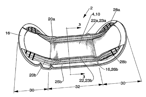
Figures 1 to 3 show a sanitary napkin 2, a preferred embodiment of an
absorbent article constructed in accordance with the present invention. The
sanitary
napkin 2, as will be understood from the following description, is not in a
substantially flat form, but is cup-shaped as illustrated in Figure I, due to
the
contracting action of a SELF web as will be described below. In Figure 2, the
entire
sanitary napkin 2 is shown in a substantially flat state with its cuffs
elongated. The
sanitary napkin 2 shown in Figures 1 to 3 has a liquid pervious topsheet 4, a
liquid
impervious backsheet 6, and an absorbent core 8 positioned between the
topsheet 4
and the backsheet 6. The sanitary napkin 2 further comprises longitudinally
extending cufif's 20, the cuiis 20 comprising a SELF web. As will be described
below,
the elastic-like properties of a SELF web cause the distal edge 23 of the
cuffs 20 to
extend upward above the plane of the topsheet 4 and provide the sanitary
napkin 2
of the present invention with a cup-like configuration
The sanitary napkin 2 has two surfaces, a body-contacting surface or "body
surface" 2A and a garment surface 2B. In a similar manner, the body surface of
other
components of the sanitary napkin 2 having a body surface will be referred to
using
the reference number for the component followed by the letter A and any
reference
to the garment surface of a component will use the reference number for the
component followed by the letter B. The sanitary napkin 2 is shown in Figure 2
as
viewed from its body surface. The body surface 2A is intended to be worn
adjacent
to the body of the wearer. At least a portion of the body surface 2A comprises
the
topsheet 4. The garment surface 2B is on the opposite side of the sanitary
napkin 2
and is intended to be placed adjacent to the wearer's undergarments when the
sanitary napkin 2 is worn. At least a portion of the garment surface 2B
comprises the
backsheet 8. The sanitary napkin 2 has two centerlines, a iongitudinal
centerline L
and a transverse centerline T. The term "longitudinal", as used herein, refers
to a
line, axis or direction in the plane of the sanitary napkin 2 that is
generally aligned
with (e.g., approximately parallel to) a vertical plane which bisects a
standing wearer
into left and right body halves when the sanitary napkin 2 is worn. The terms
"transverse" or "lateral" as used herein, are interchangeable, and refer to a
line, axis '
or direction which lies within the plane of the sanitary napkin 2 that is
generally
perpendicular to the longitudinal direction. Figure 2 also shows that the
sanitary
napkin 2 has a periphery 2I which is defined by the outer edges of the
sanitary
CA 02239516 2001-06-22
?
napkin 20 in which the longitudinal edges are designated 5 and the end edges
are
designated 7. As can also be seen in Figures 1 and 2, the sanitary napkin 2
comprises
longitudinally opposite end regions 30 and a central region 32.
The topsheet 4 should permit bodily discharges from the wearer to rapidly
penetrate its thickness for absorption by the absorbent core 8, and should not
cause
excessive discomfort to the wearer when it is in contact with the wearer's
skin. The
topsheet 4 forms at least a portion of the body surface 2A of the sanitary
napkin 2.
The topsheet 4 can be formed from materials, such as woven or nonwoven
fabrics comprising natural or synthetic fibers; apertured thermoplastic films;
porous
foams; reticulated foams; reticulated thermoplastic films; and thermoplastic
scrims.
In the preferred embodiment shown in >ragures 1 to 3, the topsheet 4 comprises
a
composite topsheet comprising a primary topsheet layer 10 and a secondary
topsheet
layer 12 (seen most clearly in Figure 3). The primary topsheet layer 10 and
the
secondary topsheet layer 1:2 are joined to form composite topsheet 4 using
means
familiar to those skilled in the art such as adhesive bonding, ultrasonic
welding, or
thermal bonding which is carried out in a multiplicity of discrete areas. An
exemplary
means for joining the primary topsheet layer 10 to the secondary topsheet
layer 12 to
form composite topsheet 4 comprises several lines of adhesive filaments
swirled irrto
a spiral pattern such as illustrated by the apparatus and method shown in U.S.
Patent
3,911,173 issued to Sprague, Jr. on October 7, 19?5; U.S_ Patent 4,785,996
issued
to Ziecker, et al. on November 22, 1978; and U.S. Patent 4,842,666 issued to
Werenicz on June ?7, 1989. In a preferred embodiment, the secondary topsheet
layer
12 may be joined to the primary topsheet layer l0 to form composite topsheet 4
by
fusion bonds. as is more fully described in published PCT Application Serial
No. WO
93/11725 on June 24, 1993.
As can be seen in Figure 2, the primary topsheef layer 10 preferably has a
substantially rectangular configuration. A portion of the primary topsheet
layer 10
extends convexly arcuately outward to form a portion of the end edges 7 of the
sanitary napkin 2. Preferably, the portion of the longitudinal edges of the
primary
topsheet 10 that lies in each of the end regions 30 is substantially linear
and parallel
to the longitudinal centerline L.
CA 02239516 2001-06-22
g
A suitable primary topsheet layer 10 may be manufactured from a wide range
of materials such as woven and nonwoven materials; polymeric materials such as
apertured formed thermoplastic films, apertured plastic films, and hydroformed
thermoplastic films; porous foams; reticulated foams; reticulated
thermoplastic films;
and thermoplastic scrims. Suitable woven and nonwoven materials can be
comprised
of natural fibers (e.g., wood or cotton fibers), synthetic fibers (e.g.,
polymeric fibers
such as polyester, polypropylene, or polyethylene fibers) or from a
combination of
natural and synthetic fibers. A preferred primary topsheet layer 10 comprises
an
apertured formed film. Apertured formed films are preferred for the primary
topsheet '
layer 10 because they are pervious to body exudates and yet non-absorbent and
have
a reduced tendency to allow liquids to pass back through and rewet the
wearer's
skin. Thus, the surface of the formed film which is in contact with the body
remains
dry, thereby reducing body soiling and creating a more comfortable feel for
the
wearer. Suitable formed films are described in U.S. Patent 3,929,135, which
issued
to Thompson on December 30, 1975; U.S. Patent 4,324,246, which issued to
Mullane, et al. on April 13, 1982; U.S. Patent 4,342,314, which issued to
Radel. et
al. on August 3, 1982; U.S. Patent 4,463,045, which issued to Ahr et al. on
July 31,
1984; and U.S. Patent 5,006,394, which issued to Baird on April 9, 1991.
The preferred primary topsheet layer 10 for the present invention is the
formed film
described in one or more of the above patents and marketed on sanitary napkins
by
The Procter & Gamble Company of Cincinnati, Ohio as "DRI-WEAVE".*
In a preferred embodiment of the present invention, the body surface l0A of
the formed film primary topsheet layer 10 is hydrophilic so as to help liquid
to
transfer through the composite topsheet 4 faster than if the body surface was
not
hydrophilic so as to diminish the likelihood that menstrual fluid will flow
off the
primary topsheet layer 10 rather than flowing into and being absorbed by the
absorbent ,cisfi~. In a preferred embodiment, surfactant is incorporated into
the
polymeric materials of the farmed film primary topsheet lsy~r 10 such as is
described
in published PCT Application Serial No. WO 93;09741 on May ?7, 1993.
Alternatively, the body surface of the primary topsheet layer 10 can be made
hydrophilic by treating it with a surfactant such as is described in U.S.
4,950,264,
issued to Osborn, III on August ~1, 1990.
= Trade-mark
CA 02239516 2001-06-22
9
The secondary topsheet layer 12 lies between the primary topsheet layer 10
and the absorbent core 8 and is joined to the inner surface of the primary
topsheet
layer 10 to form composite topsheet 4 as described above. The secondary
topsheet
layer 12 of composite topsheet 4 is similar in shape to the primary topsheet
layer 10,
but preferably with smaller longitudinal and transverse dimensions than the
longitudinal and transverse dimensions of the primary topsheet layer 10. That
is, the
periphery of the primary topsheet layer 10 is larger than the periphery of the
secondary topsheet layer 12 of composite topsheet 4. The secondary topsheet
layer
12 of composite topsheet 4 disperses bodily fluids, which have passed through
the
primary topsheet layer 10, mainly in the longitudinal direction, such that the
absorbent core 8 is more fully utilized.
The secondary topsheet layer 12 of composite topsheet 4 may serve several
firnctions including improving wicking of exudates over and into the absorbent
core.
There are several reasons why the improved wicking of exudates is important,
including providing a more even distribution of the exudates throughout the
absorbent core and allowing the sanitary napkin 2 to be made relatively thin.
(The
wicking referred to herein may encompass the transportation of liquids in one,
two
or all directions (i.e., in the x-y plane and/or in the z-direction.) The
secondary
topsheet layer 12 of composite topsheet 4 may be comprised of several
different
materials including nonwoven or woven webs of synthetic fibers including
polyester,
polypropylene, or polyethylene; natural fibers including cotton or cellulose;
blends of
such fibers; or any equivalent materials or combinations of materials.
Examples of
sanitary napkins having a secondary topsheet layer 12 of composite topsheet 4
are
more fully described in the above-referenced U.S. Pa ~ ~t 4,950,264 and the
above-
referenced Cree application. Preferably, the secondary topsheet layer 12 of
composite topsheet 4 is formed from a natural or synthetic nonwoven fabric. A
particularly preferred nonwoven material for the secondary topsheet layer 10
comprises an air laid tissue leaving a basis weight of about 3~ grams per
square
meter (gsm). A suitable material is available from Merfin Hygiene Products
Ltd., Delta, BC, Canada. Alternative nonwoven materials suitable for forming
the secondary topsheet layer l! ? of composite top sheet 4 include a nonwoven
fabric of spunbonded polypropylene fibers available from the Fiberweb
.4
Corporation of Simpsonville" SC under the tradename CELESTRA and a
nonwoven fabric formed of bicomponent fibers which have a polyethylene
sheath and a polyurethane core, which is available from the Havix Company,
of Japan, as S2416.
* = Trade-mark
CA 02239516 2001-06-22
The backsheet 6 is intended to prevent bodily fluids absorbed by the absorbent
core 8 from flowing out of the sanitary napkin and soiling the wearer and/or
the
wearer's clothing. Preferably, the backsheet 6 is impervious to liquids (e.g.,
menses
and/or urine) and is preferably manufactured from a thin plastic film,
although other
flexible liquid impervious materials may also be used. As used herein, the
term
"flexible" refers to materials which are compliant and will readily conform to
the
general shape and contours of the human body. The backsheet 6 prevents the
exudates absorbed and contained in the absorbent core 8 from wetting articles
which
contact the sanitary napkin 2 such as pants, pajamas and undergarments. The
backsheet 6 may, thus, comprise a woven or nonwoven material, polymeric films
such as thermoplastic films of polyethylene or polypropylene, or composite
materials
such as a film-coated nonwoven material. Preferably, backshrret 6 can comprise
a
flexible liquid impervious thermoplastic film such as a polyolefinic film.
Particularly
preferred films for forming the backsheet 6 include a low density polyethylene
film
having a caliper of from about 0.01 mm (0.4 mils) to about 0.05 mm (2.0 mils),
preferably about 0.025 mm ( 1.0 mil). Such a polyethylene film is sold by the
Ethyl
Corp., Visqueen Division, of Terre Haute, IN, as Model XP-39385 and by the
Clopay Corp. of Cincinnati, OH as SOFLEXX~~1401.
As shown most clearly in Figure 2, the backsheet 6 has a shape and dimensions
which are substantially the same as those of the primary topsheet layer 10 of
composite topsheet 4. The primary topsheet layer 10 of composite topsheet 4
and
the backsheet 6 are bonded uninterruptedly throughout their periphery (i. e.,
throughout the periphery 21 of sanitary napkin 2). This area of peripheral
bonding
16 is shown most clearly in Figure 2. Preferably, the primary topsheet layer
10 and
the backsheet 6 are joined in the area of peripheral bonding 16 by at least
one seal
formed by the application of pressure, with or without heat, commonly referred
to as
a crimp seal. Alternatively, the primary topsheet layer 10 and the backsheet 6
may be
joined together in any other suitable manner, such as bonding with an
adhesive.
In use, the sanitary napkin 2 can be held in place by any support means or
attachment means (not shown) well-known for such purposes. Preferably, the
sanitary napkin is placed in the user's undergarment or panty and secured
thereto by
a fastener such as an adhesive. The adhesive provides a means for securing the
sanitary napkin in the crotch portion of the panty. Thus, a portion or all of
the
garment surface of the backsheet 6 may be coated with adhesive. Any adhesive
or
glue used in the art for such purposes can be used for the adhesive herein,
with
pressure-sensitive adhesives being preferred. Suitable adhesives are Century~A-
305-
* = Trade-mark
CA 02239516 2001-06-22
11
IV manufactured by the Century Adhesives Corporation of Columbus, Ohio and
Instant Lock~'34-2823 manufactured by the National Starch and Chemical Company
of Bridgewater, NJ. Suitable adhesive fasteners are also described in U.S.
Patent
4,917,697 issued to Osborn III, et al. on April 17, 1990. Before the sanitary
napkin is placed in use, the pressure-sensitive adhesive is typically covered
with a removable release; liner in order to keep the adhesive from drying out
or adhering to a surface other than the crotch portion of the panty prior to
use.
Suitable release liners are also described in the above-referenced U.S. Patent
4,917,697. Any commercially available release liners commonly used for
such purposes can be utilized herein. Non-limiting examples of suitable
release liners are BL30MG-A Silox E1/0 and BL30MG-A Silox 4P/O both
of which are manufactured by the Akrosil Corporation of Menasha, WI.
Preferably, a release liner is used which also serves as an individual package
for the sanitary napkin 2:. Suitable release liners that also serve as a
package
for an individual sanitary napkin are described in U.S. Patent 4,556,146,
issued to Swanson, et al. The sanitary napkin of the present invention is used
by removing the release liner and thereafter placing the sanitary napkin in a
panty so that the adhesive contacts the panty. The adhesive maintains the
sanitary napkin in its position within the panty during use.
The absorbent core 8, which is disposed between the topsheet 4 and the
backsheet 6, absorbs and retains bodily fluids that have penetrated the
topsheet 4
after discharge by a wearer. The absorbent core 8 may be any absorbent means
which is capable of absorbing or retaining liquids (e.g., menses and/or
urine). The
absorbent core 8 may be manufactured in a wide variety of sizes and shapes
(e.g.,
rectangular, oval, hourglass, dog bone, asymmetric, etc.) and from a wide
variety of
liquid-absorbent materials commonly used in sanitary napkins and other
absorbent
articles such as comminuted wood pulp which is generally referred to as
airfelt.
Examples of other suitable absorbent materials include creped cellulose
wadding;
meltblown polymers including coform; chemically stiffened, modified or cross-
linked
cellulosic fibers; synthetic fibers such as crimped polyester fibers; peat
moss; tissue
including tissue wraps and tissue laminates; absorbent foams; absorbent
sponges;
superabsorbent polymers; absorbent gelling materials; or any equivalent
material or
combinations of materials, or mixtures of these. The configuration and
construction
of the absorbent core may also be varied (e.g., the absorbent core may have
varying
caliper zones (e.g., profiled so as to be thicker in the center), hydrophilic
gradients,
* = Trade-mark
CA 02239516 2001-06-22
12
superabsorbent gradients, or lower density and lower average basis weight
acquisition zones; or may comprise one or more layers or structures). The
total
absorbent capacity of the absorbent core should, however, be compatible with
the
design loading and the intended use of the sanitary napkin. Further, the size
and
absorbent capacity of the absorbent core may be varied to accommodate
different
uses such as incontinence pads, pantiliners, regular sanitary napkins, or
overnight
sanitary napkins. Exemplary absorbent structures suitable for use as the
absorbent
core of the present invention are described in U.S. Patent 4,950,264 issued to
Osborn on August 21, 1990; U.S. Patent 4,610,678 issued to Weisman et al. on
September 9, 1986; U.S. Patent 4,834,735 issued to Alemany et al. on May 30,
1989; European Patent Application No. 0 198 683, The Procter & Gamble
Company, published October 22, 1986 in the name ofDuenk, et al.; and U.S.
Patent
5,009,653 issued to Osborn, III, on April 23, 1991.
The longitudinal and transverse dimensions of core 8, as it is shown in Figure
2, are preferably smaller than the longitudinal and transverse dimensions of
the
primary tapsheet layer 10 and the backsheet 6. Preferably, core 8 lies within
the
region defined by the areas of peripheral bonding 16 between the primary
topsheet
layer 10 and the backsheet 6. More preferably, the secondary topsheet layer 12
of
composite topsheet 4 is disposed between the core 8 and the primary topsheet
layer
and the longitudinal and transverse dimensions of the secondary topsheet layer
l2
of composite topsheet 4 are somewhat larger than or substantially equal to the
longitudinal and transverse dimensions of core 8.
The top surface (i. e., the surface closest to the topsheet 4) of the core 8
is
joined to the lower surface of the secondary topsheet layer 12 of composite
topsheet
4, while the lower surface of the core 8~ is joined to the inner surface or
top surface
of the backsheet 6. The core 8 may be joined to the secondary topsheet layer
12 of
composite topsheet 4 and to the backsheet 6 using means known to those skilled
in
the art (not shown) such as by bonding using a suitable adhesive. Preferably
the core
8 is joined to the secondary topsheet 12 and to the backsheet 6 using an open
pattern
network of filaments comprises several lines of adhesive filaments swirled
into a
spiral pattern as discussed above. Adhesives which have been found to be
satisfactory are manufactured by H. B. Fuller Company of St. Paul, MN under
the
designation HL-1258 or H-2031. Alternatively, the core 8 may be joined to the
secondary topsheet layer 12 of composite topsheet 4 and/or the backsheet 6 in
any
other suitable manner, such as by ultrasonic welding or thermal bonding.
CA 02239516 1998-06-03
WO 97/20533 PCT/US96/18946
13
With further reference to Figures 1 to 3, the preferred embodiment of the
sanitary napkin 2 of the present invention further comprises a pair of cuffs
20a and
20b. In a similar manner, pairs of elements that are disposed on opposite
sides of the
sanitary napkin 2 will be referred to using the reference number for the
element
followed either by the lower case letter a or the letter b. Each of the cuffs
20a and
20b is disposed on the body surface of the topsheet 4 .in an elongated state,
and is
joined to the topsheet 4 in that elongated state as is described below. As
will be
easily understood by reference to Figure 3, the web comprising each of the
cuffs 20a
and 20b is first folded back along longitudinally extending lines 22a and 22b.
to
provide a two-layer configuration and to form distal edges 23a and 23b and
opposed
proximal edges 25a and 25b. The folded cuffs 20 are elongated to a
predetermined
length and disposed on topsheet 4, one cuff 20 on each side of centerline L,
with the
distal edges 23a and 23b directed inwardly toward and substantially parallel
with
longitudinal centerline L and the proximal edges 2Sa and 25b lying juxtaposed
with
the longitudinal edges 5 of topsheet 4.
Each of the cuffs 20a and 20b has the respective layers of the two-layer
structure thereof joined together adjacent the proximal edges 25a and 25b
thereof,
and is further bonded, using first bonding means 26a and 26b, to the primary
topsheet layer 10 of the topsheet 4, throughout that portion of each cuff 20a
and 20b
that lies within the area of peripheral bonding I6 iyirig along the
longitudinal edges
5. Preferably, such first bonding means 26 comprises the application of
pressure,
with or without heat, commonly referred to as a crimping, although other
means,
such as, adhesive bonding or ultrasonic bonding are also suitable. A portion
of each
cuff 20a and 20b is then bonded to the underlying portion of the cuff 20 with
second
bonding means 27a and 27b. Second bonding means 27 also bonds the cuffs 20 to
the primary topsheet layer 10 in that portion of the peripheral bonding area
16
adjacent the end edges 7. Preferably, such second bonding means 27 are same as
those used to comprise first bonding means 26. Optimally, first bonding means
26
and second bonding means 27 combine such that the area of peripheral bonding
16,
which joins the topsheet 4 to the backsheet 6, is formed at the same time the
cuffs 20
are bonded to the topsheet 4. Alternatively, the cuffs 20a and 20b can be C-
folded as
described above, disposed on the topsheet 4 in an elongated configuration, and
bonded to the topsheet in a single crimping step that combines the effects of
first
bonding means 26 and second bonding means 27 while forming the area of
peripheral bonding 16.
CA 02239516 1998-06-03
WO 97!20533 PCTlUS96/18946
14
The portion of the cuffs 20 lying in end regions 30 are further joined to
underlying structure using tertiary bonding means 28 at a plurality of spaced
apart
sites. Importantly, at least portion of the plurality of sites for tertiary
bonds 28a and
28b overlie core 8 to prevent the corners of sanitary napkin 2 from bending in
toward the longitudinal centerline L. The tertiary bonds 28a and 28b disrupt
the
"elastic-like" structure of the cuffs 20a and 20b (discussed below) so there
is no
contractive force in end regions 30 to cause the corners to bend in. Further,
cuffs
20a and 20b are locally joined to the relatively stiff core 8 via the primary
topsheet
layer 10, effectively transmitting the contracting action of cuffs 20a and 20b
to core
8. This transmission of forces further resists the undesirable local bending
in the four
corners of the sanitary napkin 2. Consequently, the topsheet 4, backsheet 6
and core
8 are caused to extend inclinedly upward away from the plane of the central
region
32 in each of the end regions 30, forming the desired cup-like configuration.
For
example, three sites of tertiary bonds 28a and 28b are shown in Figures 1 and
2. As
can be seen in Figure 2, one of such bonds 28a and one bond 28b do not overlie
core
8. While the remaining two bonds 28a and 28b do overlie core 8. Preferably
tertiary
bonds 28 comprise dynamic mechanical bonds as described in US Patent
4,854,984,
issued to Ball, et al. on August 8, 1989. Alternatively, other suitable
methods, such
as, thermal bonding, crimping, or ultrasonic welding may be employed as
tertiary
bonding means 28 to join the cuffs 20a and 20b to underlying structure in the
end
regions 30.
As noted above, cuffs 20a and 20b are disposed on the topsheet 4 in an
elongated state, and are bonded thereto by bonding means 26a and 26b, 27a and
27b, and in spaced apart sites 28a and 28b. When the force that has maintained
the
cuffs 20a and 20b in an elongated condition is released, the unbonded portions
of the
cuffs 20a and 20b contract, and thus, the cuffs 20a and 20b, at least
partially, return
their original lengths. This contracting action generated in the cuffs 20a and
20b,
causes the topsheet 4, the backsheet 6 and the core 8 to be displaced so that
end
regions 30 lie above central region 32 as is clearly illustrated in Figure 1.
Thus, the
sanitary napkin 2 is brought into the shape of a cup as a whole. In addition,
in central
region 32, the distal edge 23 of each of the cuffs 20a and 20b extends upward
and
away from the plane of the topsheet 4 forming a barrier which impedes the
lateral
flow of bodily fluids with a resulting reduction in leakage along the
longitudinal
edges 5 of the sanitary napkin 2. The degree of elongation imparted to the
cuffs 20a
and 20b when they are disposed on the topsheet 4 and thermally bonded thereto
depends on the overall configuration and dimensions of the sanitary napkin 2.
For
CA 02239516 2001-06-22
IS
the embodiment of the present invention shown in Figures I to 3 elongation
should
be between about I 10% to about 160%, preferably, between about 115% and about
145%, and, more preferably, about 125% of the length of an unelongated cuff
20.
In the sanitary napkin 2 of the present invention, the cuffs 20a and 20b are
formed from a web formed at least partially in a non-planar configuration to
provide
a "Structural Elastic-Like Film" (SELF) web. A particularly preferred
embodiment
of a SELF web is a web comprising a thermoplastic film, especially, a
polyolefinic
film such as a polyethylene film, which includes, in a suitable combination,
formed
portions formed in a non-planar configuration as described below, and unformed
portions retained in a substantially planar configuration. SELF webs are
described in
detail in copending PCT Patent Application Serial No. WO 95/03765. When the
cuffs 20a and 20b are produced from a web including formed portions and the
longitudinally extending uniformed portions as are described below, the
contracting
action of the cuffs 20a arid '?Ob is generated mainly by the restoring force
of the
unformed portions, as will be; clearly understood from the following
description.
As used herein, the term "formed" refers to the creation of a desired
structure
or geometry upon a web of material that will substantially retain the desired
structure
or geometry when it is not subjected to any externally applied elongation or
forces.
Methods suitable for forming a web of material such that the web is
transformed into
a SELF web include, but are not limited to, embossing by mating plates or
rolls,
thermoforming, high pressure hydraulic forming, and casting.
Figures 4 and 5 show a web 34 in the form of a SELF web that is suitable for
cuffs 20a and 20b. This web 34 comprises foamed portions 36 formed in a non-
planar configuration as described below, and unformed portions 38 retained in
a
substantially planar configuration. As is seen clearly in Figure 4, the formed
portions
36 and the unformed portions 38 are arranged alternately in a side-by-side
relationship in the transverse direction (shown by arrows 43 in Figure 4), and
extend
uninterruptedly in the longitudinal direction (shown by arrows 44 ~in Figure
4). As
will be understood by reference to Figures 4 and 5, the formed portion 36
includes a
primary formed portion 40, and secondary formed portions 42 located on both
sides
in the transverse direction. As seen most clearly in Figure 5, the primary
formed
portion 40 takes a substantially uniform, nearly sinusoidal form in its
longitudinal
CA 02239516 1998-06-03
WO 97/20533 PCT/US96/18946
16
cross section, and takes a substantially horizontally extending linear form in
its
transverse cross section. The secondary formed portion 42 is a region of
transition
from the primary formed portion 40 and the unformed portion 38.
The proportion of the unformed portions 38 in the web 34 is between about
1% and about 30%, preferably between about 3% and about 20%, more preferably
between about 5% and about 12%, when calculated as the ratio of the respective
areas (assuming that the web 34 is in a non-elongated state and the area
occupied by
formed portions 36, including the primary formed portions 40 and the secondary
formed portions 42, is projected to the plane of unformed portion 38). This is
illustrated by the projection shown in the non-elongated plan view of Figure
4. In
other words, the proportion of the formed portions 36 (including the primary
formed
portions 40 and the secondary formed portions 42) in the web 34 is between
about
70% and about 99%, preferably between about 80% and about 97%, and more
preferably between about 88% and about 95%. If the proportion of the unformed
portions 38 in the web 34 is too high, the force required to elongate the
cuffs 20a
and 20b tends to become too high. If the proportion of the unformed portions
38 in
the web 36 is too low, the contractive force of the cuffs 20a and 206 is
minimal,
making it difficult to shape the sanitary napkin 2 into the desired cup-like
configuration.
Furthermore, since the formed portions 36 are in a non-planar configuration,
they touch the skin of the sanitary napkin 2 wearer only locally at a
plurality of small
spaced apart regions. Consequently, the discomfort they may cause to the
wearer is
limited because the sanitary napkin 2 can "breathe". In contrast, if the
proportion of
the unformed portions 38 is too high and the unformed portions 38 are the main
source of contact between the sanitary napkin 2 and the wearer' s skin, the
unformed
portions 38 in a planar configuration touch the wearer's skin uninterruptedly
over a
relatively large area. Thus, they may cause discomfort to the wearer.
Generally, as
can be seen in Figure 4, the width Wl of the formed portion 36 is 0.25 to
50.80 mm
(0.01 to 2.00 inches), preferably, 3.18 to 25.40 mm (O.I3 to 1.00 inch), while
the
width W2 of the unformed portion 38 is 0.25 to 12.70 mm (0.01 to 0.50 inch),
preferably, 0.76 to 6.35 mm (0.03 to 0.25 inch).
The web 34 shown in Figures 4 and 5 exhibits desirable "elastic-like" behavior
when the cuffs 20a and 20b are stretched in the longitudinal direction
indicated by
arrows 44. When a longitudinal stretching force is exerted on the web 34, its
cross
sectional configuration is geometrically changed as illustrated in Figure 6,
with the
CA 02239516 2000-06-29
17
amplitude of the formed portions 36 being gradually decreased. Upon a further
elongation, the web 34 becomes substantially planar as shown in Figure 7.
During
the change of the formed portions 36 from the state illustrated in Figure 5,
to the
state in Figure 6, and, finally, to the state shown in Figure 7, the force
contribution
of the formed portions 36 to the total force resisting the elongation is
markedly low.
The unformed portions 38, on the other hand, are elongated by molecular-level
deformation of the constituent material itself, and the resistive force of the
web 34 to
elongation is mainly provided by the unformed portions 38. In other words, in
the
range where the elongation of the formed portions 36 is attributable to
geometric'
deformation, rather than to the molecular-level deformation of the material
itself the
contracting action of the web 34 upon release of a stretching force exerted on
the
web 34 results mainly from the contracting action due to molecular-level
deformation of the unformed portions 38.
An alternative way of describing this behavior is shown in Figure 8, which
shows the relationship between a longitudinally exerted tensile force and
elongation
for a SELF web 34, such as is shown in Figures 4 and 5. Curve 710 depicts the
results of measurements of a IongitudinaUy exerted tensile force and the
resulting
elongation for a web comprising only unformed portions ~.e., an unconverted or
base web). Specifically, the web elongated to generate Curve 710 comprised a
linear
low density polyethylene film, approximately 1 mil (0.025 mm) in thickness,
TM
designated SOFFLEX 1401 which is available from Clopay Corp., Cincinnati, OH.
Curve 720 shows similar measurements for a formed or SELF web comprising the
same linear low density polyethylene film as was used for the film of curve
710. As
can be seen in curve-720, the SELF web 34 has a two stage tensile profile:
Stage I
(curve portion 720a) wherein a relatively low tensile force provides a
relatively high
elongation, and Stage II (curve portion 720c) where a sharply increased
tensile force
is required to provide a given elongation. In the Stage I elongation range,
release of
the tensile force results in substantially complete contraction of the web 34
defining
..
the portion of the tensilelelongation curve available to pct~,v~ide elastic-
like stretch to
the cuffs 20a and 20b. When the web 34 is to be used as a material for cuffs
20a and
20b in the sanitary napkin 2 illustrated in Figures 1 to 3, it is important
that the
elongation of the web 34 be maintained in the Stage I region. Suitable
adjustments
can be made by varying the shape of curve 720 in Figure 8. For example, the
stress/strain properties of a material to be formed into a SELF web, the
relative
proportions of the formed portions 36 and the unformed portions 38 in the web
34,
and so on all can be varied to vary the shape of curve 720.
CA 02239516 2001-06-22
18
Figure 9 shows one processing means 44 that is suitable to convert a planar
film web into a SELF web. The processing means 44 includes a pair of rolls
sets 46
and ~8 which act cooperatively to convert a planar film web into a SELF web.
Roll
set 46 has toothed regions .'S0 and grooved regions 52 arranged alternately in
the
transverse direction, each toothed region 50 having a multiplicity of teeth 54
around
its circumference. Similarly, roll set 48 has toothed regions 56 and grooved
regions
58 arranged alternately in the transverse direction, each toothed region 56
having a
multiplicity of teeth 60 around its circumference. Toothed regions 50 of roll
set 46
and the toothed regions 56 of roll set 48 are positioned in mating transverse
locations as are the corresponding grooved regions 52 and 58. The mating
toothed
regions and grooved regions work cooperatively to convert a planar web into a
SELF web as follows. When an substantially planar web is fed between roll sets
46
and 48 which are continuously rotating in the direction shown by arrows 62,
the
portions of the web passing through the toothed regions 50 and 56 are
stretched past
their yield value by the mating teeth 54 and 60, producing the formed portions
36.
The portions of the web passing through the grooved regions 52 and 58 of roll
sets
46 and 48 are not stretched, but left in a substantially planar configuration,
defining
the unformed portions 38. As is obvious to one skilled in the art, the number
of and
relative degree of engagement of the teeth 54 and 60 and the relative
transverse
widths of the toothed regions 50, 56 and the grooved regions 52, 58 can be
varied to
vary the properties of the SELF web 34.
Web materials suitable for conversion into a SELF web 34 are preferably
thermoplastic films, particularly polyolefin films, including linear low
density
polyethylene, low density polyethylene, ultra low density polyethylene, high
density
polyethylene, polypropylene, or blends of these. Additional suitable web
materials
include polyester, polyurethanes, compostable or biodegradable polymers, heat
shrink polymers, thermoplastic elastomers, metallocene catalyst-based polymers
"_
(e.g., INSTT~ available from Dow Chemical Company IVlsdland, MI, and Faotact',
available from Exxon Chemical Corp. Bay City, T7~, and~b'reathable polymeric
films.
Also suitable are webs comprising synthetic woven materials, synthetic knit
materials, nonwoven materials, apertured films, macroscopically expanded three-
dimensional formed films, absorbent or fibrous materials, foams, filled
compositions,
and laminates and/or combinations thereof.
As has been noted above, the cuffs 20a and 20b are folded along longitudinally
oriented lines 22a and 22b to provide a two-layer configuration and to form
distal
edges 23a and 23b. If the cuffs 20a and 20b are formed from the SELF web 34
= Trade-mark
CA 02239516 1998-06-03
WO 97/20533 P'CT/US96/18946
19
described in Figures 4 to 9, the lines 22a and 22b can extend either along
unformed
portion 38 as shown in Figure 10, or along formed portion 36 as shown in
Figure 1 I.
When lines 22a and 22b are extended along the unformed portion 38, the distal
edges 23a and 23b become relatively sharp, providing a good seal with the
wearer's
skin. When lines 22a and 22b are along formed portion 36, the distal edges 23a
and
23b are provided with minute "vents" with resulting improved comfort during
wear.
Preferably the fold lines 22a and 22b are positioned in unformed portion 38 to
minimize the risk of lateral leakage of bodily fluids.
As has also been mentioned above, cuffs 20a and 20b are thermally bonded to
the topsheet 4 at a plurality of sites for tertiary bonds 28a and 28b in
addition to the
first bonding means 26a and 26b and second bonding means 27a and 27b which
join
the cuffs 20a and 20b to the topsheet in the area of peripheral bonding 16.
Since the
contractive force of the curs 20a and 20b is generated mainly by the unformed
portions 38 as described above, it is important that the tertiary bonds 28a
and 28b be
positioned such that the bond area includes unformed portions 38. Also, the
bond
area for tertiary bonds 28a and 28b should preferably be minimized to minimize
the
creation of occluding areas that can cause wearer discomfort. One way to
nunimize
the bond area is to provide tertiary bonds 28a and 28b at a plurality sites,
each
having a relatively small area, which are disposed at spaced apart locations
instead of
providing one bond 28a and one bond 28b each having a relatively large area at
each
end of each of the cuffs 20. Such a mufti-site configuration for tertiary
bonds 28a
and 28b is shown in Figures 1 and 2.
A particularly preferred pattern relationship between the formed portions and
the unformed portions of a SELF web is shown in plan view in Figure 12 and in
perspective view in Figure I3. Figure 12 shows a SELF web I10 that not only
comprises laterally oriented formed portions I22 and longitudinally oriented
unformed portions (fold line 112, hinge 114, and longitudinal band 116) but
also
diagonally oriented angled band I I8. As is shown most clearly in Figure I2,
angled
band lI8 is disposed at an angle a with respect to a tine parallel to the
formed
portions 122. As can also be seen in Figure 12, the web is symmetrical about
the fold
line 112.
' As can be seen in Figure 14, such a web is suitable for use as a cuff 520 of
sanitary napkin 502. When web 110 is folded about fold line lI2 as is
described
above and shown in Figure 13, the distal edge 523 of cuff 520 is formed. The
cuff
CA 02239516 1998-06-03
WO 97/20533 - PCT/US96/18946
520 is then extended, disposed on, and joined to the body surface 504A of
composite topsheet 504 as described above.
Angled band 1 I8 provides a cuff, such as cuff 520 shown in Figure I4, with a
bi-directional force vector that causes cuff 520 to rotate about hinge 114 in
a
direction outward from centerline L with a resulting lifting of the distal
edge 523 of
cuff 520 in the vertical or "z" direction with respect to the body surface
504A of
composite topsheet 504 even when the sanitary napkin 520 is in a substantially
flat-
out configuration. The angle a (shown in Figure 12) is particularly important
with
respect to the degree of lifting provided by angled band 118. For example, if
angle a
is about 30 degrees {i.e. about 60 degrees with respect to the longitudinal
centerline
L), there is insufficient lifting force to cause the distal edge 523 to be
displaced
upward when the sanitary napkin 502 is in a substantially flat-out
configuration.
{Such a substantially flat-out configuration is encountered during sanitary
napkin use
by medium to large size wearers.) Preferably, the angle a is between about 45
degrees and about 75 degrees {i.e. between about 15 degrees and about 45
degrees
with respect to the longitudinal centerline L). In a particularly preferred
embodiment,
the angle a is about 60 degrees (i.e. about 30 degrees with respect to the
longitudinal
centerline L).
The spacing between the fold line 112 and the hinge 114 is also important.
Formed portions 122 create laterally oriented pleats which resist bending. If
the
spacing between fold line 112 and hinge 114 is too small there is insufficient
bending
resistance against externally applied forces such as those encountered during
the
wear cycle and the cuff 520 would tend to fold over and inward during use.
Said
another way, longitudinally directed unformed portions provide a preferential
fold
line and, if such unformed fold lines are positioned between the arcuate seal
529 and
the distal edge 523 of the cuff 520, unacceptable fold over may occur. It has
been
found that a spacing between fold line 112 and hinge 114 of between about 0.3
inches (8 millimeters) and about 0.6 inches (16 millimeters) is satisfactory.
Particularly preferred is a spacing of about 0.5 inches (12 millimeters)
between the
fold line 112 and the hinge 114. It is also important that, whatever spacing
is used,
the spacing is greater than the cuff height. This is shown most clearly in
Figure 14
wherein hinge 114 is positioned outboard of the arcuate seal 529.
It is also important that angled band 118 intercept both the fold Line 112 and
the longitudinal band 116. This intersection of bands causes the line of
tension that
causes the distal edge 523 of cuffs 520 to be elevated above the body surface
504A
CA 02239516 2000-06-29
21
of composite topsheet 504 to be carried through the fold line 112 to the
angled band
118 for transfer to underlying layers of the sanitary napkin 502 in end
regions 530.
This is shown most clearly in Figure 16 which shows how the line of tension
150 is
directed along the various unformed portions of the preferred SELF web.
As can also be seen in Figure 12, fold line 112 comprises two portions 112a
and 112b. While both portions are unformed, portion 112a is substantially
narrower
than portion 112b. The narrower unformed portion 112a helps insure that the
line of
tension is carried along angled band I 18 rather than continuing along the
distal edge
523 (i.e. fold Line 112) since portion 112a will stretch more readily in
response to an
applied force. However, it is necessary that fold line 112 be continuous to
enable
web 110 to be folded to form cuff 520 and distal edge 523 in a reliable
manner.
This preferred embodiment of a SELF web is further illustrated in Figures 14
and 15 which show, in addition to cuffs comprising an angled band 118, an
alternative embodiment of the present invention, sanitary napkin 502 as having
two
flaps 507a and 507b each of which are adjacent to and extend laterally from
the side
edge of the absorbent core in at least a central region 532. The flaps are
configured
to drape over the edges of the wearers panties in the crotch region so that
the flaps
are disposed between the edges of the wearers panties and the thighs. The
flaps
serve at least two purposes. First, the flaps help serve to prevent soiling of
the
wearer's body and panties by menstnral fluid, preferably by forming a double
wall
barrier along the edges of the panty. Second, the flaps are preferably
provided with
attachment means on their garment surface so that the flaps can be folded back
under
the panty and attached to the garment facing side of the panty. In this way,
the flaps
serve to keep the sanitary napkin properly positioned in the panty. The flaps
can be
constructed of various materials including materials similar to the topsheet,
backsheet, tissue, or combination of these materials. Further, the flaps may
be a
separate element attached to the main body of the napkin or can comp>yse
extensions
k
of one or more of the topshcet, the backsheet, and the cv~s ~.e., unitary). A
number
of sanitary napkins having flaps suitable or adaptable for use with the
sanitary
napkins of the present invention are disclosed in U.S. 4,687,478 entitled
"Shaped
Sanitary Napkin With Flaps", which issued to Van T'~butg on August 18, 1987;
U.S.
4,589,876 entitled "Sanitary Napkin", which issued to Van Tilburg on May 20,
1986;
and U.S. 4,608,047, entitled "Sanitary Napkin Attachment Means", which issued
to
Mattingly on August 26, 1986.
CA 02239516 1998-06-03
WO 97/20533 PCT/US96/18946
22
Figures 14 and 15 show this alternative embodiment of the present invention,
sanitary napkin 502. As can be seen in figure 14, the sanitary napkin 502
comprises a
main body portion 534 and a pair of laterally extending flaps 507a and 507b.
The
main body portion 534 is defined by end edges 536 and side edges 538. A
portion of
each side edge 538 comprises an arcuate seal 529. The sanitary napkin 502
further
comprises a central region 532 and two end regions 530.
Flaps 507a and 507b lie in at least the central region 532 of the sanitary
napkin
502 and extend laterally outward beyond the side edge 538. As noted above, the
flaps may be folded about the leg elastics of a wearer's panties and joined to
the
outside surface of the panties. Preferably, as also noted above, a pressure
sensitive
adhesive (not shown) may be disposed on the garment surface of flaps 507a and
507b adjacent the distal edge thereof (i.e., the surface which contacts the
outside
surface of the wearer's panties when the flaps are folded back) to separabIy
join the
flaps to the wearer's panties. The pressure sensitive adhesive may be covered
with a
silicone-coated paper (not shown) prior to use. Suitable materials are
described
above with respect to sanitary napkin 2
As is best shown in Figure I S, each of the flaps 507a and 5076 preferably
comprises an extension of the primary topsheet layer 510, the backsheet 508,
and a
portion of the cuff 520. The components of each flap 507 are joined to each
other
adjacent the main body portion 534 by arcuate sea! 529. Arcuate seal 529 can
comprise any sealing means known to the art such as ultrasonic welding,
adhesive
bonding, or other means known to the art. Thermal bonding is particularly
preferred
for forming arcuate seal 529. The components of each flap 507 are joined about
the
periphery 509 of the flap 507 by flap seal 525. While flap seal 525 may
comprise any
of the means discussed above as suitable for forming the arcuate seal 529, a
preferred means is to use a combination of heat and pressure commonly known to
the art as crimping to form flap seal 525.
Alternatively, the flaps 507 can comprise separate elements that are joined to
one of composite topsheet 504, the backsheet 508, or both composite topsheet
504
and the backsheet 506 using means known to those skilled in the art such as
ultrasonic welding, adhesive bonding, or other means known to the art. Each of
the
flaps 507a and 507b may comprise any suitable material. For example, flaps
507a
and 507b may comprise the same material as used for the primary topsheet layer
510
of composite topsheet 504 or the same material as used for backsheet 506. If
desired, the flaps 507a and 507b may comprise a SELF material similar to that
used
CA 02239516 2000-06-29
23
for cuffs 520a and 520b. In this case, they may be bonded to the backsheet 506
in a
non-elongated state or with slight longitudinal elongation. Preferably for
such an
embodiment, the flaps 507a and 507b comprise the same material used for the
primary topsheet layer 10 as described above.
The cuffs 520 are formed, disposed on, and joined to the main body portion
534 in substantially the same manner as described above with respect to the
sanitary
napkin 2 of the present invention. That is, the proximal edges 531 of the
cuffs cuffs
520 are joined along those portions of the side edges 538 that do not comprise
the
arcuate seal 529 and along portions of the end edges 536 using first bonding
means
526 and second bonding means 527. The arcuate seal 529 further joins the
proximal
edge 531 of the cuff 520 to the main body portion 534. Those portions of each
cuff
520 lying in the end regions 530 are further provided with tertiary bonds 528.
Preferably, the cuffs 520 are elongated to between about 110% and about 160%
of
their unstretched length before being disposed on and joined to the central
absorbent
body 534. More preferably the cuffs 520 are elongated to about 125% of their
unstretched length before being disposed on and joined to the main body
portion
534. Cuff height can be between about 3 millimeters and about 15 millimeters.
Preferably cuff height is between about 6 millimeters and about 12
millimeters. A
particularly preferred cuff height is about 8 millimeters. As used herein, the
term
"cuff height" is intended to mean the distance along the transverse centerline
T
between the proximal edge and the distal edge of a cuff.
The remaining components of sanitary napkin 502, as illustrated in Figures 14
and 15, are substantially the same in construction as those of sanitary napkin
2, as
depicted in Figures 1 to 3, and are, thus, described in detail above.
To use a sanitary napkin 502 of the present invention, a wearer would 5rst
remove any release liner that has been provided and position the sanitary
napkin 502
in the crbtch region of her panties, insuring that the flaps,»~7 are folded
over the leg
:~
elastics of the panties and that any attachment means provided are used to
join the
sanitary napkin to the panty. She would then pull the panties on in the normal
manner.
It is expressly not admitted that any of the commercially
available materials or products described herein teach or disclose
the present invention.
CA 02239516 2000-06-29
24
While particular embodiments of the present invention have been illustrated
and described, it would be obvious to those skilled in the art that various
other
changes and modifications can be made without departing from the spirit and
scope
of the invention. It is therefore intended to cover in the appended claims all
such
changes and modifications that are within the scope of this invention.
i
_. ,............ ...