Note: Descriptions are shown in the official language in which they were submitted.
CA 02239645 1998-06-OS
1
TITLE OF THE INVENTION:
method and apparatus for locating a drill bit when
drilling out cementing equipment from a wellbore
NAME ( S ) OF INVENTOR ( S )
Robert Lawrence Ryll
FIELD OF THE INVENTION
The present invention relates to a method and apparatus
for locating a drill bit when drilling out cementing equipment
form a wellbore.
BACKGROUND OF THE INVENTION
As a well is drilled, sections of casing are positioned
in the wellbore to contain formation fluid within the formation
and prevent such fluid from entering into the wellbore. In
order to secure the casing in position, a cement slurry is
pumped down the interior of the casing and then is forced up
through the annulus between the casing and the wellbore. After
solidifying, the cement locks the casing into the wellbore.
In order to prevent the cement slurry from returning to
the interior of the casing, downhole cementing equipment is
used that include check valves . A shoe is placed at the bottom
of the casing string. The shoe may be either a float shoe
which has a check valve or a guide shoe which does not. A
float collar having a check valve is placed one to five
sections of casing above the float shoe or guide shoe. Cement
is used in the manufacture of the cementing equipment, as it
is easily drillable. The cement used in the manufacture is
similar in composition to the cement slurry that is pumped into
the well to retain the casing string within the wellbore.
Cementing plugs are used to separate the well fluid from the
cement. A bottom plug is placed into the casing before cement
is pumped into the casing. A top plug is placed on top of the
cement after it has been completely pumped into the casing.
During the pumping process, both of these plugs are displaced
down on top of the float collar.
CA 02239645 1998-06-OS
2
After the cementing is completed and the cement has
solidified, the well operator will re-enter the casing with a
drill bit to drill the well to a greater depth. In doing so,
the operator will drill through the cementing plugs, the float
collar, the cement remaining inside the casing between the
float collar and the shoe, until the undrilled formation is
reached.
At the present time it is very difficult to determine the
location of the drill bit while drilling out the cementing
equipment from a wellbore. This is most important if the
cement plugs have not been completely displaced to the top of
the float collar. It is not uncommon for this to occur if
incorrect calculations have been made for displacement of
fluid, the method of determine displacement of fluid volume is
incorrect, or if the check valves in the cementing equipment
did not operate properly.
SZTMMARY OF THE INVENTION
What is required is a method for locating a drill bit when
drilling out cementing equipment from a wellbore
According to one aspect of the present invention there is
provided a method for locating a drill bit when drilling out
cementing equipment from a casing of a wellbore. The first
step involves placing in the casing of the wellbore at the time
of placing cementing equipment, at least one coloured marker
member. A second step involves monitoring cuttings during
drilling for traces of colour. Penetration of a drill bit into
the cementing equipment is indicated by coloured cuttings from
the at least one coloured marker member.
With the method, as described above, penetration into of
the drill bit into the cementing equipment is readily
determined by monitoring the cuttings for coloured cuttings
from the marker member. The marker member need not be a
separate component. Pigment can be added to the float collar,
the shoe or both during fabrication. It is preferred, but not
CA 02239645 1998-06-OS
3
essential, that the float collar and the shoe be of differing
colours so as to reduce the risk that the coloured cuttings
will be inadvertently misconstrued.
According to another aspect of the present invention there
is provided an apparatus for locating a drill bit when drilling
out cementing equipment from a wellbore. The apparatus
includes at least one coloured marker member incorporated as
part of a downhole assembly of cementing equipment. It is
preferred that either the float collar, the cementing shoe or
both be used as the coloured marker member.
BRIEF DESCRIPTION OF THE DRAWINGS
These and other features of the invention will become more
apparent from the following description in which reference is
made to the appended drawings, wherein:
FIGURE 1 is a side elevation view, in section, of a float
collar and a float shoe in accordance with the teachings of the
present invention, prior to cementing.
FIGURE 2 is a side elevation view, in section, of the
float collar and the float shoe illustrated in FIGURE 1, with
top and bottom plugs in position after cementing.
FIGURE 3 is a side elevation view, in section, of a float
collar and a guide shoe in accordance with the teachings of the
present invention, prior to cementing.
FIGURE 4 is a side elevation view, in section, of the
float collar and the guide shoe illustrated in FIGURE 3, with
top and bottom plugs in position after cementing.
DETAILED DESCRIPTION OF THE PREFERRED EMBODIMENT
The preferred method will now be described with reference
to FIGURES 1 through 4.
Referring to FIGURE 1, a casing string 10 is illustrated
positioned in a wellbore 12, prior to pumping of a cement
slurry down casing string 10. Casing string 10 consists of a
CA 02239645 1998-06-OS
4
plurality of casing pipes 14. A float shoe 16 is positioned
at bottom 18 of the lowermost ones of casing pipes 14. Float
shoe 16 has a body 20. A check valve 22 is encased in pigment
coloured cement 24 within body 20. Positioned one section of
casing pipe above float shoe 16 is float collar 26. Float
collar 26 has a body 28. A check valve 30 is encased in
pigment coloured cement 32 within body 28. In accordance with
the teachings of the method, pigment coloured cement 32 within
body 28 of float collar 26 is intended to serve as one coloured
marker member and pigment coloured cement 24 within body 20 of
float shoe 16 is intended to serve as another coloured marker
member.
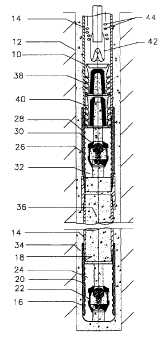
Referring to FIGURE 2, there is illustrated how the
components illustrated in FIGURE 1 would appear after cement
slurry is pumped down casing string 10. Cement slurry
solidified in the annulus is identified by reference numeral
34. Cement slurry solidified in interior 36 of casing string
10 is identified by reference numeral 36. No coloration is
added to cement slurry 34 and 36. It remains it's natural
coloration which is readily distinguishable from the coloration
of pigment coloured cement 24 and 32. A top plug 38 and a
bottom plug 40 are shown positioned above float collar 26 where
they would normally come to rest after being displaced during
the process of pumping cement slurry down casing string 10.
A drill bit 42 is shown in casing string 10 in the process of
drilling. Cuttings 44 are shown rising to surface. Cuttings
44 are monitored during drilling for traces of colour.
Penetration of drill bit 42 into float collar 26 is indicated
by coloured cuttings from pigment coloured cement 32.
Similarly, as drilling progresses, coloured cuttings from
pigment coloured cement 24 indicates penetration of drill bit
42 into float shoe 16.
Referring to FIGURE 3, an alternative configuration is
illustrated in which a guide shoe 46 is substituted for float
shoe 16. The difference between guide shoe 46 and float shoe
CA 02239645 1998-06-OS
16 is that float shoe 16 has a check valve 22, whereas guide
shoe 46 does not. Guide shoe 46 has a body 48 containing
pigment coloured cement. Apart from this difference the
components in FIGURE 3 as compared to FIGURE 1 and FIGURE 4 as
5 compared to FIGURE 2 are identical and will be assigned the
same reference numerals. In accordance with the teachings of
the method, pigment coloured cement 32 within body 28 of float
collar 26 is intended to serve as one coloured marker member
and pigment coloured cement 50 within body 48 of guide shoe 46
is intended to serve as another coloured marker member.
Referring to FIGURE 4, cuttings 44 are monitored during
drilling for traces of colour. Penetration of drill bit 42 into
float collar 26 is indicated by coloured cuttings from pigment
coloured cement 32. Similarly, as drilling progresses,
coloured cuttings from pigment coloured cement 50 indicates
penetration of drill bit 42 into guide shoe 46.
It will be apparent to one skilled in the art that
modifications may be made to the illustrated embodiment without
departing from the spirit and scope of the invention as
hereinafter defined in the Claims.