Note: Descriptions are shown in the official language in which they were submitted.
CA 02239844 l998-06-08
ACTUATING DEVICE
Background of the Invenlion
The present invention relates to an ac~uating device ~or
di~pensing a paste-like materi~l, especially in the dental field, from
a capsule or cartridge, whereby the actuating device has an
abu~ment for suppor~ing the capsule or cartrid~e within the actuatin~
device in the direcUon of dispensing.
Such an actuating device is known from US Patent
~.472,141. This ac~ating devioe compnses a handle which acts on
a plunger by which a pa~t~like material ~or dental purposes is
d;spensed from a capsule or cartridge. According to US Patent
4,~72,141, a lhTeadable closure cap and an undercut in the forrn of
a counter collar are provided at the capsule or car~ridge which are
c~nnec~ed ~o the f~rward e~d of the actuating device. The force to
1~ be applied by the handle onto the plunger and thus onto the capsule
or carlridge is, in general! a multiple of the manual force applie~
whereby due to the selected le~erage ratio, ~or example, five ~imes
~he manual forc4is applied to the pas~e-like material.
Sin~e ~he spacing between the pressure application of the
handle and i~s ~ivot axis s~lpasses the spacin~ between the pivot
axis and the follower of the plunger, for example, by a hctor 5, the
applied plunger force can thus have a "~agni~de of one kN or even
Lrr TQ~L otF 197 26 e~.~ ~ rvocru~ ~265~-JI18.22~
CA 02239844 1998-06-08
;
more. ~fith respect to this force, there is the risk that the capsu1e or
car~ridge will break o~ut of ~he comparatively thin screw cap or will
deform ;n the area of ~he counter coll~r such that a safe supporting
action is no longer possibl~. This is true especially ~~/hen the ~crew
cap is not securely applied becau~e then it is not ensured that the
caps~ie or cartridge is properly supported with its counter collar
between the undercut of the screw cap and a sealing ring or the
forward end of the exterior thread. On the other hand, when
m~nipulating the actuating device it is not always detectable
whether the screw cap has been completely secured.
Another actuatin~ device is known ~rom European Patent
Application A1-63 891. This actuating device con prises a
downwar~ly opcn channel i~ which th6 cartridge is secured. The
ear~ridge is oversized relative to ths sidewalls of the cl-annel and,
acc~rdingly, ~he channel sh~uld be some~hat flexible in order to be
able to introduce the cartridgs from the open side.
This arrangement, h~wever, h~s no~ been pro~en successful
in practice. {:~ue So the tight guiding of the counter collar within the
channel, which i~ requir~d for reasons of s~abitity, the cartridge upon
removal must be guided exactly parallel to the axis of the plunger
present in the device. tlowever, since it can be gripped only at its
~orward end, there is always the risk that the cai l-ids~a upon removal
Ll~ ~RSL d P IP~ 25 ~.8 ~ IVOCLAR ~2CCJ~ .229
CA 02239844 1998-06-08
will jam and the counter collar of the cartridge will bec~me jamrned
in the guide. The user then assun~es lhat an incre2sed actuating
~orce must be applied which he can do without a problem, but will
result in that ~he cartridge can break, resulting in undesirable
contamin~tion of the actua~ing device 8S well as of the
surroundings. This is especially a problem when mercury-containing
amalgam n~aterials are used as a paste-like material in the
dispensing or actuating device.
It is therefore an object of the present invention ~o provide an
actuating device of the aforemenlioned kind which allows a safe
actuation at high actuating f~rces ~ith easy removal of the cap~tJIe
or cartridge.
Summary of the Invention
The actuating device for dispensing a paste ma~érial from a
cartridge according to the present invention is primarily
~haracten'zed by:
a housing having a fo~ard and a rearward end;
the housing accommodating a car~ri~ge containing a
paste n~aterial at the fo~ard end;
a plunger slidably arranged in the rearward end of the
housing and acting on the car~ridge for dispensing the pa~te
mc~rial when actuated;
a pivot handle pivotably conne-,~d to the housing for
LIT 7R~ o~P 1~7 2~ ~61~ . IVOCLAR 2657~ .229
CA 02239844 1998-06-08
actuating the plunger:
at least one securing fongue c~nnec~ed to th
housin~;
the at least one securing tongue releasably securing
the cartridge at the housing; and
the at least one securing tongue comprising a
projecting collar having an abutment ~or supporting the carSridge in
a di~pensin~ direc~ion.
Between hr~o and ~of the securing ton~ues are preferab1y
1 0 present.
The act~Jating device may fur~her comprise a slide sleeve
moveably supported at the housing and h~ing a securing posi~ion
in which ~he ~-ar~ridge is secured in the housing and a release
position in which the car~ridge is released from the housing.
In the securing por~;on of the slide sleeve the abutment
se~ures the cartridge by engaging a counter abutment of the
cartridge to thereby prevent the cartridge from being forced out of
the housing when lhe plunger is actuated.
The cartrid~e has a plunger and the plunger of the housing
acts on the plunger of the cartridge in order to dispense the paste
material.
In the reîease position of the sl;de sleeve the canridge is
ejected from the housing by actuating the handle and the plunger of
Ll~ T7?SL. o~P 1~7 25 86~.t ~IWCLAR~ 2657~ 18.22Q
CA 02239844 1998-06-08
the housing.
The projecting collar has a radial extension that is greater
than a radial ex~ension o~ She counter abutment of the cartrid~e.
The projecting collar has a sJanted surfa~e opposite the
abutment, wherein the slznted surface is direcled radially inwardly
and faciliSates in~ertion of the carlridge into the housing by
spreading the securing tongues radially oulwardly.
The slide sleeve is preferably held in the release posit70n and
in the secur;ng posiSion by a frictional connection or a snap
1 û connection.
The cartridge has a counter abutment. In the securing
position of the slide sleeve, the cartridpe is slidable in the housing
~hereby a travel stroke o~ the cartridge is limited by the counter
~butment.
The slide sle~ve in the securing position supports a radially
outer surface of the securing tongues.
The slide sleeve in ~he securing position is positioned radially
outwardly of the projecting collar and overlaps partially the
projecting collar.
The projec~ing collar extends at le~st over a portion of its
radial extension at a slant fo~ardly at an angle of 70~ to a
longitudinal axis of the housing.
The securing tongues are preferably unitary parts of t!~e
~,
L~r~sL~ ~pl~2~663.s~rvo~xA~-2657~r~
CA 02239844 1998-06-08
housing and are radially outwardly prestressed and tensioned by the
~1ide sleeve in the securing position.
The slide sleeve has a first thickened p~r~ion at a fo~ard end
and a second thickened portion at a rearward end and ~urther has
an annular grip depression between the first and second thickened
portions.
The slide sleeYe h~S an inner bevel at the forwarcl end.
The counter abutment has an axial length Shat is greater than
a wall thickness of the car~ridge, preferPbly, the axial length is twice
the wall thickness.
The actuating device may further comprise a locking member
for locking in ~he release position the plunger of the car~ridge,
wherein the locking member is a locking ~ongue acting, depending
on a position of the slide sleeve, as a altemat~e to the abutment
1~ and the projecting collar.
The cartridge comprises a counter abutment enga~ing
behin~ the projecting collar.
The counter abutment is overlapped bythe slide sleeve in the
securing position such that the slide sleeve projects forwardly past
a contact surface for the abutment.
The inventive actuating device allows ~or a safe securing due
to the unita~ consaruction of the shaft of the actuating device and
the collar-shaped proj__tion provided as an abutment Sor 8ecuring
-6-
Llr ~SL ~ P 1~7 2S e~.o ~ rvocLAR ~ 2~5~-n-1e.229
CA 02239844 1998-06-08
the capsule or cartridge. This allows sliding of the slide sleeve into
a locking position in which it surrounds the securing area of the
tongues for supporting the capsule or cartridge so that a sa~e
supporl is enslJred because the spring-elastic tongues cannot move.
On the other hand, the locking position can be e~sily rec~gnized
bas~d on the posftion of the slide sleeve.
Furtherrnore, this invention surprisingly allows for the
possibility to remove the completely empty Gapsule or cartridge from
the actuating device by employing ~he handle of the actuating
deYi~e af~er release of the slide sleeve. Since ~he actu~Ung ~orce
applied by the handle onto the ca~ridge is substantial~y greater than
the manually applied force, this solution allows for a comparatively
stiff embodiment of the projections (projecting collars) provided for
anchoring and also ~or the embodiment of the abutments at a
slanted position close to 90~.
The invention is also advan~ageous with resp~ct to a
con~tructively clean separat;on bet~een the sprin~ ~unction.for
releasing and introducing the cartridge, on the one hand and the
securing function via the stiff slide sleeve, on the other hand.
~ccording to a further advant~geous embodiment, it is
suggested that a plurality o~ tongues extends annularly about the
~apsule or ca, Iridge. The tongues end in a thickened portion whlch
Llr 7RSL. d P 197 25 863.8 ~ IVOCLAR 26S7~J1 18.229
CA 02239844 1998-06-08
radially inwardly forms the collar-shaped projection (projecting
collar) and radi~lly outwardly provides an ab-ltment for the slide
sleeve. The radia11y inwardly oriented projection extends to t~le
exSerior wall of the capsule or ca~rid~e so that the capsule or
cartridge is supported at the projection in the radial direction and is
guided in the axial direc~ion. This provides for the possibility to guide
the cartridge in a slidabl~ manner axi~tly into the end position which
is defined by the abutment be~eGn the collar-shaped projecfion
and the counter eollar. Since the cartridge comprises a slantediy
1~ extending outlet, the mo~bility in the rearward direction is limit~d
by the out~et abut~ing the for~ard end o~ the respective tongue. In
the securing position the slide sleeve is a~ially positi~ned such that
the rearward end of the capsule or car~ridge proj~cts considerably.
However, there is no overl~p beh~een the slide sleeve and the
capsule or cartridge in the release position of the slide sleeve. It is
preferrPd that in this posiUorl a considerable radial spacing is
provided.
The relative dimensions in the radial direction al10w for
adjusting whether the contact bet~een actuating device and
cartridge is realized between the exferior wall of the cartridge and
the projection at the tongues or between the outer s~rface of the
coun~er collar (counter abutment) and the inner surface of the
-8-
LIT T~L o~P 19~ 25 8B3.8 . rv~AQ . 26s~-~J-~e.~~
CA 02239844 1998-06-08
tongue or at both loc~tions. In order to ensure a large support area,
it ;s pre~erred to provide the cont~cS location between the projecti~n
of the tongues and the exterior ~urface of the car~ridge.
The tongues at thelr for~ard ends have preferably an inner
bevel or radially inwardly oriented slanted surfaces which facilitate
introduc~ion of the cartridge when the slide slee~e is in the release
position.
Brief Description of the Drzwings
The object and the advan~ages of the present invention will
appear n ore clearly from ~he f~llowing specification in conjunction
with the accompanying drawings~ in which:
Fig. 1 shcws a part-sectional side view of one
embodiment of the inventive actua~ing device;
Fig. 2 shows the embodiment according to Fig. 1 in a
Yiew from the left, i.e, ~ view of the actua~ng
device frcm the front;
Fig 3 shows a part-sectional view of the actuating
device accordin~ to Fig 1;
Fig 4 shows the actuating device acoording to Fig. 1
illustrating the position of the handle in the
actuated positions;
Fig. S shows an enlarged detail of the etnboc irnent
g
L17 ~SL ~P ~~7 25 ~63.~ ~ JVOCLA~ 657-rl-1~,~9 ,
CA 02239844 1998-06-08
shown in Fig. 4
Fig.6 shows a schema~ic front view of the actuating
device with representation of the tongues:~
Fig. 7 sliows a Vi2W according to th~ representation
of Fig. 4 whereby the slide sleeve is in the
release position;
Fig. 8 shoY,rs a view according tc Fig. 5, whereby the
slide sleeve is in its release position;
Fig 9 shows an enlarged representation of the
forward por~ion of She inventive actuating
de~ice, the cartridge not being represented;
Fig. 10 shows the slidD sleeve ~or the inventive
actuatin~g device:
Fig. 11 shows a representation of the front portion of
1~ the inventive actuating device in a second
embodiment;
Fig. 12 shows a representation of thesecond
embodiment according to Fig. 11 whereby the
capsule is removed and the slide sleeve is in
its release position.
Description of Preferred Em~odiments
The present imention will now be disclosed in detail with the
- 10 -
LJ~ LofP~Q~26~63.$ IVOCLAR-26SJ~1116.~2P
CA 02239844 1998-06-08
aid of the embodiments of Figs. 1 through 12.
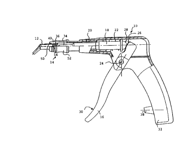
The shov~n embodiment of th~ a~uating device 10
represented in Fig. 1 is suitable ~or dispensing dental materials
(pastes~ and is embodied in the ~orm of an injector. The device 10
secures a capsule or cartridge 12 at its forward end 14. The
ac7uating device has a handle 16 whic~7 acts on a plunger 18. The
plunger 18 is movably suppor~e~ within the housing 20 of th~
aotuating device 10 and is elastically tensioned by a pressure spr;ng
22 in the direction of the handle. The handle 16 ;s pivotably
1~ supponed at a pivot pin 24 and acts with ~s curYed or ~pherical
pressure surface 26 onto the plunger 18 which also has a curved or
spherical pressure su~ace 28 able ~o slide or glide along the
pressure surfa~e 26.
The spacing between the pressure suf~ces 2B and 28 and
the be~ring pin 24 that provides the pi~ot axis for the grip 16 ;s
slJbstantially smaller than the spacing between the actuatin~
depression 30 of the handle 16. ~he ratio of the spacing is
~pploxil"alely 1: 5 so that onto the plunger 18 almo~t 5 times the
force o~ the manval force applied on the grip 16 is provided. The
actuaffng device 10 is essentially pistol-shaped so that already the
basic design results in an ergonomic actuation and ~avorable ~orce
Sransln,ssion for mov~ment of the handle 16 tow8rd the pistol grip
- 1 1 -
L l~ ;L ol P ~97 2~ 63. J - r~OCLAR ~ 26S7~1r~ 1~.229
CA 02239844 1998-06-08
32. The applied force is ~ransmiffed by ~he plunger tip 34 onto ~he
cartrid~e 12.
The ~artridge 12 comprises a plunger 36 onto which the lip
34 acts. The outer dian~eter of the tip 34 is somewhat smaller than
t~e dia~eter of the plunger 36 so that the tip 34 can enter the
cartridge 12 and is able to dispense the denial material contained
in the cartridge 12 via the force applied by the plunser 36. The
denta1 material is not represented in th ~ Figures.
As can be ~oen when comparing the representation of Figs.
1 and 4, the handle 16 for dispensing the dPntal material can be
pivoted from a left into a right end po~ition. In the ri~ht end position
the hand1e 16 rests at thD ~top 38 which se~es as a travel limiter.
~rom this positi~n, the plunger 18 is moved toward the left, i.e.,
toward the fon~ard enci 14 of the housing 20, whereby the pressure
~prin~ 22 is compressed. lhe plunger 18 tapers in a stepped
manner to ~he f~rward end wherebY in the shown embodiment two
~teps are provided.
At ~he forward end 14 the hou~ing 20 has a pluralty of
securin~ tongues 14 to 46 which can be seen especiaily well in Fig.
2. Each securing tongue 4~ to 45 extends approximately about a
quarter circle about the cartridge circumference. Be~e., them
slots 48 are pruvid~ which pro~ide for an elastic e" ,bod;n~el ,t of the
LlrTRSL5~P-9725~,8~ rvo~R ~ z~57~rt~ ~.229
CA 02239844 1998-06-08
tongues. The tongues 40-46 end in a thickened portion 50 whic
exSends radially inwardly as well as outwardly. The radially outer
projec~ion ~f the thickened portion 5~ provides an abutrnent Sor the
movement of a slide sleeve or clarnping bushing 52 which can be
moved between a securing position. represented in Fig. 1, and a
relea~ posilion, represented in Fig. 7. In the securing position ,the
slide sleeve ~2 overlaps the tongues 4û to 46 up to the thickened
portion 50, while in the release position according to Fig. 7 She
tongues are substantially ~ree over their entire length and are thus
spring-elastic and movable.
The slide sleeve 52 prevents in She securing position a radial
movement of the tongues 4~ to 46 because it surrounds the
tongues in an annular configuration.
A respect;ve collar-shaped projection (projecting collar) 54
extends radially inwardly from the lhic~ened portion 50. The design
of the collar-shaped projection is represen~ed in d~tail in Figs. ~ 8,
and 9 so as to prcvide a better illuctration. At its rearward end the
projecting collar 54 provides an abutment 5~ for the cartridge 12.
The cartridge 12 at its rear ~nd has a counter collar (counter
abutment) 58 which extends radially outwardly.
The radial extension of the counter collar 58 is somewhat
smaller than that of the projecting collar ~4 so that the surface 60 of
Llr rfisL o~ P 7~ 26 863.8 tVC)CLAR. 2657-J1 78.229
CA 02239844 1998-06-08
the projection (projecting collar) 54 pointing radially inwardly
provides a gliding ~ur~aoe for the outer surface 62 of the cartridge
12. The car~ridge 12 in ~he shown embodiment is slida~le in the
axia1 directi~n whereby the con7act between the abutment ~6 ~nd
~he co~lnter collar 58 delim;ts the movement in the forward direch~n.
The abutment 56 in the shown embodiment has a slanted
~urface having an angle of slant of app,~,xilnalely 70~ re1ative to the
axis 64 of the housing 20 of ~he actuating device. This slanted
sur~ace allows, on ~he one hand, a sa~e support of the secl~ring
position o~ the slide sleeve 52. and, and on the other hand, a
removal or ~orcing-out of the caffridge 12 in the release position of
the slide ~leeve 52. For removing or pressing-out the cartridge, the
tongues 40 to 4~ ~re spread by the slan~ed abvtments 56 to such
an ex~ent lhat the s~ots 4~ ~re widened and the counter collar 58
~an be p~sitioned within fhe area of the surface 60. In this spread
position of the tongue 40 to k6 ~he cartridge 12 can be easily
remov~d.
The projections 54, as can be seen especially in Fig. g, have
at their ~o~ard end an insertion ~lant 66. The insert;on slant 66
points radially inwardly 2nd serves ~or spreading the tong~ es 40 to
4~ upon insertion of the cartridge 12 in the release position of the
slide sleeve 52. The degree of slant of the i,)s~i liGn slant 66 is
- 14 -
Ll~ ~7?SL. oJ P 1~7 25 86~.8 . IVOCLA~ . 265; tl 19.22P
CA 02239844 1998-06-08
substantialty flaffer than the degree of ~lant of the abutment 56
since ~or the insertion of the cartridge 12 the handle 1~ and the
plunger 18 must not be av~ilable ~or applying an auxiliary force but
the cartridge 12 must inslead be manually inserted.
The counter collar 58 occupies a comparati~ely large axial
length of the ca~ridg~ radius. Even ~or a certain elastic defonnation
in the removal direction the coLJnter collar ~8 thus remains as a safe
ab~ltment despite the comparatively minimal radial dimension o~ the
abutment 56 as well as o~ ~he counter collat ~8. This de~i~n is
fa\~orable with respect So the slim design concept of She in~entiYe
actuating de~ice and of the inventive injector.
The inventive embodimenl is especially advantageous with
respect to the ~latively small number o~ par~s which are securely
at~ached to one anoSher so that they are sui~able for a safe and
reliable operation even for very viscous materials whilD realizing a
~lim ~ctuating devic~. While in the shown embodiment the radial
extension of the thickened por~ion which has adiacent to the
inser~ion slant 65 at its forward radially outward pointing end a bevel
68 corresponds approxi",ately to the radius of the car~ridge 12 it
is vnderstood tha~ a rnodified embodiment also allows considerably
reduced or enlarged dimensions.
It is cspecially favorable that in the represented embodiment
- 15 -
Lr~RSLorPlg72~863.J-~V~UR~26S~ 7J.229
CA 02239844 1998-06-08
in ~he ~ecuring position of the slide sleeve 52, the slide sleeve 52
projects as an extension of the very n~ bevel that extends, for
example, at an angle of 20~ relative to th~ axis 64 and does not
proj~ct to the exterior. This ~acilitates manipulation. However, the
slide sleeve 52 provides a wide grip depression 70 which c~n been
en especiallY in Fig. 10.
As can be seen in Fig. 4, the plunger 18, in the position
farthest to the left, can move with i1S forward end 34 the plunger 36
~o such an extent in the ~o~ard direction that it abuts the forward
end of the cartridge 12 so th~t only ~he area of the outlet 72 is still
filled with the visc~is material.
For removing the car~ridge, the slide sleeve 52 is moved to
~he right in Fig. 7 so that it is in ~he release position. It is
advantageous when the st~p 38 is slightly elastic so th~t by a slight
pressure applied via the handle 16 and the plunger 18 onto the
plunger 36, restlng already at the forward end of the cartridge 12,
the spreading resistance o~the tongues is overcome by cooperation
of the abutment 55 and Vle counter collar 58, and the emp~y
cartridge 12 can then be manually easily removed.
The inventive actuating device is characteri.ed furthermore
by allowing for dispensing of the viscous material, for example, a
dental material, in a single dispensing step but also In any desired
LIT TRSL. c~l P 197 2~ 863. ~ ~ IVOCUR - 2657-lr-16.229
CA 02239X44 1998-06-08
n~.lmber of steps. When the dental ma~eria~ is dispensed in a
plurality of steps, ~s a function of the required amount, an easy
m~nipulation is provided in lh~t the handle 16 is returned into its
ini~ial position by the pre~sure spring 22. The us~r actuates, ~or
example, for a half-empty cartridge 12 She handle again up to half
of the actuating travel whereby the tip 34 of the plunger 18 is then
in contact at the plunger 36 and a resi~tance can be felt. Upon
fsurther actuation of the handle 16, the dental material is then
dispensed until the cartridge 12 is empty In this position, the
1~ handle 16 rests at the stop 38 and lhe cartridge 1~ can then be
removed as disclosed abo~e ~y ap,~lyin~ only a manual Sorce via the
h~ndle 16.
As can be seen in Fig. 8, lhe ~lots 48 end at their rea~ard
end in a radius 74. Even for frequent ~preading of the tongues. an
actuation wi~hout notching, and thus a long service life and
operation of t~-e inventive actuating device, is ensured.
A further embodiment of the inventive actuating device is
~hown in F;g. 11 and 12. Fig. 11 shows the sleeve 52 in the
securing position for the cartridge 12 so that, in analogy to the
representati~n of Fig. 1, 4, and 5. the counter co11ar ~8 is secured
in a forrn-locking manner by the pr_jEctil-g collar 54 and the capsuie
12 cannot be pr~ssed ~.~ut by the pressure forc~ ~ the pl~nger 18
Lt'r ~St oJP l g7 2S 863. J /ItOCLAR ~ 26s7 /l ?e.~~2s
CA 02239844 l99X-06-08
~rom the actuating devic~.
In this position, tongue or p~ier-shaped locking members are
not functi~ning. They are arranged, in lhe return position of the
plunQer 18, in the area of bl.lt in front o~ the step 78 of the plunger
18 whereby the radial extension of the locking mem~er 7~ is
selected such that the plunger 18 can be freely moved, e~en with its
greater diameter adjacent to ~he step 78, and will not be locked by
~he locking members 76.
The locking members 76 are provided at tongues connected
1~ to the housing 2~ which, in analogy to the tongues 40 to 46, are
moveable in their forward- area. Two oppositely arranged tongues
are pro~ided whereby the housing 20 projects past the locking
members 75 in the forward direction. The locking members 76
have at their ~oTward/outer ends an insertion slant 80 ~or the slide
1~ slee~e 52. Upon return movement of the sle~ve ~2, i.e., upon
sliding into the release position, the sleeve 52 compresses ~he
locl~ing n7embers 76 radially invvardly so that they move toward one
another with their inwardly positioned projections and provide a
diamPter which is smaller than the diameter of the plunger 18 in the
area adjacent to the step 78.
This position is shown in Fig. 12.
When comparing Figs. 11 and 12, the sleeve 52 th~ls secur~s
- 1 8 -
~Ir 77~SL. dP 1~ ~6 863.8 - IvocLAf:~ ~ 26s7-lr-18~229
CA 02239844 1998-06-08
ei~her the tongues 40 ~o 46 so that ~hey cannot be moved outwardly
or the tonQue-shaped locking members ~6 so that they cannot move
outwardly whereby the re~pective other tongues are releàsed.
This inventive embodiment has the advsntage that ~ detltist
cannot accidentally forget, afler inser~ion of ~he capsule ~r cartridge
12, to move the sleeve 52 ~o~ardly. It is ~hus ensured that the
capsl~le cannot accidentally be eJected at high pressure in the
forward direc1ion so that any risk of injury is thus prevented. In
practice, the ac~uation of ~he actuating ~evice is locked as long as
the sleeve 52 has not been moved into the securlng position.
The present invention is, o~ course. in no w~y restricted to the
speci~lc discloswe of the specification and drawings, but also
es-comp~sses any modifications urithin the scope of the appPnded
claims.
- 19-
LIT 7~RSL otl' 197 2~ r~t.~ ~ r~focLAR ~ 2~5; IS 1J.~s