Note: Descriptions are shown in the official language in which they were submitted.
CA 022398~1 1998-06-08
M~l~O~ FOR DERIVING SURFACE CONSISTENT REFLE~llvllY MAP
FROM DUAL SENSOR SEISMIC DATA
The present invention relates generally to marine
seismic prospecting and, more particularly, to a method
for using production Dual Sensor seismic data to determine
water bottom reflectivity in a surface consistent manner,
that is, determining the different values at different
locations.
In marine seismic prospecting, a seismic survey ship
is equipped with at least one energy source and at least
one receiver for taking seismic profiles of an underwater
land configuration. The act of taking profiles is often
referred to as "shooting" or taking "shots" due to the
fact that explosive devices had been commonly used for
many years as energy sources. An energy source is
designed to produce compressional waves that propagate
through the water and into the underwater subterranean
land formations. As the compressional waves propagate
through the subterranean formations, they strike
interfaces between formations, commonly referred to as
strata, and reflect back through the earth and water to a
receiver. The receiver typically converts the detected
waves into electrical signals which are later processed
into an image that provides information about the
structure of the subterranean formations.
Presently, one of the most common marine energy
sources is an air gun that discharges air under very high
pressure into the water. The discharged air forms an
energy pulse which contains frequencies within the seismic
range. Another marine energy source which is frequently
used is a marine vibrator.~ Marine vibrators typically
include a pneumatic or hydraulic actuator that causes an
CA 022398~1 1998-06-08
acoustic piston to vibrate at a range of selected
frequencies.
Just as different energy sources may be used to
generate acoustic waves in marine applications, different
receivers may be used to detect reflected acoustic waves.
The receivers most commonly used in marine seismic
prospecting are hydrophones. Hydrophones convert pressure
waves into electrical signals that are used for analog or
digital processing. The most common type of hydrophone
includes a piezoelectric element which converts physical
signals, such as pressure, into electrical signals.
Hydrophones are usually mounted on a long streamer which
is towed behind the survey ship at a depth of tens of
feet.
Alternatively, marine seismic prospecting may use
different types of receivers which detect different
characteristics of the environment. For instance, in Dual
Sensor bottom cable seismic recording, a combination of
pressure sensitive transducers, such as hydrophones, and
particle velocity transducers, such as geophones, are
deployed on the marine bottom. Geophones are typically
used in land operations where metal spikes anchor the
geophones to the ground to maintain correspondence of
geophone motion to ground motion. In marine applications,
however, anchoring the geophones is difficult. Typically,
therefore, cylindrical gimbal geophones are attached to
the bottom cable. After the cable is deployed from the
seismic survey ship, the geophones lie in contact with the
marine bottom where they fall. The gimbal mechanism
inside the cylinder orients the geophone element
vertically for proper operation. Typically, miles of
bottom cable are deployed in a planned pattern such as a
single line or several substantially parallel lines.
The use of water bottom cables is particularly
effective in obtaining full three dimensional coverage in
areas too shallow or too congested with obstacles for
gathering seismic data with a towed streamer. While the
CA 022398S1 1998-06-08
bottom cable technique allows access to areas denied by
the towed streamer method, an additional, unwanted "ghost"
reflection from the air-water interface, along with
subsequent reverberations, occurs for each primary
reflection wave. The time delay between the primary
reflection signal and the ghost reflection signal is
greater with the bottom cable method than with the towed
streamer method because the detectors are farther removed
from the air-water interface, except in shallow water.
Two basic approaches have been proposed for
eliminating the ghost reflection. The first approach
involves recording signals from detectors at different
depths and performing a wavefield separation. The second,
and operationally more straightforward, approach, utilizes
co-located pairs of pressure and velocity detectors, as
in, for example, U.S. Patent No. 2,757,356, "Method and
Apparatus for Canceling Reverberations in Water Layers",
issued to Hagarty. This second approach capitalizes upon
the fact that pressure and velocity detectors generate
signals which are the same polarity for upward travelling
waves but are of opposite polarity for downward travelling
waves, that is, the ghost reflections. This indicates
that the two signals can be properly scaled and summed to
eliminate the unwanted reverberations associated with each
reflection. In the frequency domain, this relationship
expresses itself in the complimentary amplitude spectra of
the two sensors. When the signals are properly summed, a
smooth amplitude spectrum results.
U.S. Patent No. 4,979,150, issued to present co-
inventor Barr, assigned to the assignee of the present
invention, and entitled "Method for Attenuation of Water-
Column Reverberations" describes a Dual Sensor bottom
cable method for attenuating the unwanted water column
reverberations associated with each reflection signal in
the seismic data by combining the pressure and velocity
signals recorded at each receiver station. Proper
combination of the pressure and velocity signals, in order
CA 022398~1 1998-06-08
to remove the component of the signal representing energy
which is trapped in the water layer, can only be performed
after scaling the velocity signal by a scale factor S
given by
_ (1 + R)
S (1 - R)'
where R is the water bottom reflectivity. Thus the scale
factor requires determining the water bottom reflectivity,
which depends upon the acoustic impedance of the bottom
material. Since the acoustic impedance of the bottom
material, and hence the water bottom reflectivity, can
vary among different source and receiver locations, the
scale factor can be expected to vary at different
locations too. A "surface consistent" map of water bottom
reflectivities gives the different values at different
locations.
In the past, a calibration survey has been used to
estimate the water bottom reflectivity R. In the dual
sensor operations described above, an estimate of the
water bottom reflectivity is made by collecting separate
reference information, generated by shooting a small
seismic source directly over the receivers. The
collection of this survey data requires additional time
and cost beyond the data acquisition phase of the survey.
U.S. Patents 5,396,472 and 5,524,100, both issued to
present co-inventor Paffenholz, assigned to the assignee
of the present invention, and entitled "Method for
Deriving Water Bottom Reflectivity in Dual Sensor Seismic
Surveys", describe a method which allows the determination
of the water bottom reflectivity directly from the
production Dual Sensor seismic data rather than from
additional calibration data, and describe the advantages
of using this method over the prior art. The advantages
include deriving water bottom reflectivity from production
data without relying on the ratio of the first breaks and
CA 022398~1 1998-06-08
without being affected by clipped first signals. A third
advantage is in providing a method of combining trace data
to eliminate peg-leg reverberations. However, while the
operator used in the Paffenholz patents acknowledges the
existence of source and receiver side reverberations, it
is assumed that the pertinent parameters, water bottom
reflectivity and water depth, are similar at the source
and the receiver locations. This does not yield a surface
consistent map of reflectivities.
The present invention is a method for determining
surface consistent water bottom reflectivities using
production Dual Sensor seismic data. Pressure signals and
velocity signals are combined to generate combined signals
havin~ signal components representing downwardly-
travelling energy substantially removed. The pressure and
velocity signals correspond to seismic waves generated at
source locations n in a water layer and detected by co-
located pressure and velocity receivers at receiver
locations m in the water layer. The combined signals
correspond to each pairing of source location n and
receiver location m. The combined signals are transformed
from the time domain to the frequency domain, generating
transformed signals. A source peg-leg term and a receiver
peg-leg term are calculated for each transformed signal,
generating filtered signals. An optimization algorithm is
applied to the filtered signals and uses the corresponding
source and receiver peg-leg terms to determine the
possibly different water bottom reflectivity values Rn and
Rm at each of the source locations n and the receiver
locations m, respectively.
A better understanding of the benefits and advantages
of the present invention may be obtained from the appended
detailed description and drawing figures, wherein:
Fig. 1 is an illustration of apparatus used in a
bottom cable operation;
Fig. 2 is an illustration of source and receiver
peg-leg reverberation sequences;
CA 022398~1 1998-06-08
Fig. 3 is a flow diagram of the preferred
implementation of the present invention using the inverse
split Backus filter;
Fig. 4 is a flow diagram of the alternative
implementation of the present invention using a spectral
decomposition into source and receiver components; and
Fig. S is a flow diagram of the alternative
implementation of the present invention for eliminating
the peg-leg multiple sequence.
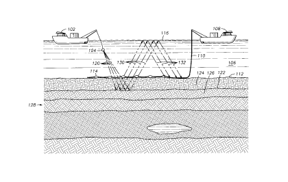
Fig. 1 illustrates a preferred marine seismic survey
system, generally designated by 100. The system 100
includes a seismic survey ship 102 that is adapted for
towing a seismic energy source 104 through a body of water
106. The seismic energy source 104 is an acoustic energy
source or an array of such sources. An acoustic energy
source 104 preferred for use with the system 100 is a
compressed air gun, constructed and operated in a manner
conventional in the art. The system 100 also includes a
receiving ship 108 that is preferably anchored in the body
of water 106. The receiving ship 108 deploys one or more
cables 110 on the marine bottom 112, and receives signals
from the cables 110. The cables 110 carry at least one
receiver 114 each, but normally include a plurality of
receivers 114.
The receivers 114 include hydrophones for detecting
water pressure and geophones for detecting water bottom
particle velocity. More particularly, the hydrophones and
geophones on the cables 110 are arranged so that each
hydrophone has at least one gimballed geophone positioned
next to it, when the cables 110 are deployed on the marine
bottom 112. Electrical signals are sent to a recording
system on the receiving ship 108 from the hydrophones and
geophones. The survey ship 102 fires the source 104 at
predetermined locations while the signals from the
hydrophones and geophones are recorded. The signals are
recorded by a multi-channel seismic recording system (not
shown) that selectively amplifies, conditions and records
-
CA 022398~1 1998-06-08
time-varying electrical signals onto magnetic tape.
Advantageously, the seismic recording system also
digitizes the received signals to facilitate signal
analysis. Those skilled in the art will recognize that
any one of a variety of seismic recording systems can be
used.
According to a preferred practice, the cables 110 and
their associated receivers 114 carrying hydrophones and
geophones are positioned on the marine bottom 112.
Production shooting takes place with the survey ship 102
moving at a constant speed along a set of parallel lines,
or swath, perpendicular to the cables 110. After the
survey ship 102 completes the swath, the receiving ship
108 or other suitable ship retrieves the cables 110 and
re-deploys the cables 110 in lines spaced from, but
parallel to, the previous cable locations. Once the
cables 110 are re-deployed, the survey ship 102 shoots
another swath.
During data collection, seismic waves generated by
the source 104 travel downwardly, as indicated by the rays
120. These primary waves are reflected off of interfaces
between strata, such as the interface 122 between strata
124 and 126, in the subterranean earth formation 128. The
reflected waves travel upwardly, as illustrated by the
rays 130. The hydrophones and geophones which comprise
the receivers 114 detect the reflected waves 130. The
receivers 114 generate electrical signals representative
of pressure and particle velocity changes in the seismic
wave field, and transmit these generated electrical
signals back to the survey ship 108 via the cable 110.
The seismic recording system within the survey ship 108
records these electrical signals so that they can be
subsequently processed to map the subterranean earth
formation 128.
The receivers 114 detect both reflected waves of
interest and unwanted reverberated waves which are noise.
Reverberated waves are seismic waves which reflect off the
CA 022398~1 1998-06-08
water-air interface at the surface 116 of the water one or
more times before finally traveling downwardly in the
water 106 to impinge on the receivers 114. An example of
reverberated waves is illustrated by the rays 132 in Fig.
1. Peg-leg reverberation waves contain at least one
reflection from an interface 122 between strata in
addition to the reverberations between the water surface
116 and the marine bottom 112. The order of the peg-leg
is the number of reflections from interfaces between
strata.
Fig. 2 illustrates three examples of first order
peg-leg reverberation sequences. A first order peg-leg
reverberation sequence is defined above as a seismic wave
which reaches the subsurface interface 222 once in
addition to water trapped reverberations. In the first
example of Fig. 2, the downward travelling wave 240 from
seismic energy source 204 travels downward through water
layer 206 and strata 224 until reflecting up from
interface 222, which provides a subsurface reflector.
Next the upward travelling wave 242 travels back through
strata 224 and water layer 206 to the water surface 216.
Then the wave reverberates through the water layer 206
between the water surface 216 and the marine bottom 212
until it reaches receiver pair 214. This first example is
called a "receiver peg-leg reverberation sequence" since
the reverberations in the water layer 206 occur near the
receiver 214 location. In the second example of Fig. 2,
the downward travelling wave from seismic energy source
204 reverberates through the water layer 206 until the
downward travelling wave 244 travels though water layer
206 and strata 224 and is reflected from interface 222.
Then upward travelling wave 246 moves back through strata
224 and water layer 206 to water surface 216. There the
wave again reverberates through the water layer 206
between the water surface 216 and the marine bottom 212
until it reaches receiver pair 214. The second example is
a regular first order peg-leg reverberation sequence. In
CA 022398~1 1998-06-08
the third example of Fig. 2, the wave from seismic energy
source 204 first reverberates through the water layer 206
between the water surface 216 and the marine bottom 212.
Then the downward travelling wave 248 passes through water
layer 206 and strata 224 until reaching interface 222.
There the wave reflects and upward travelling wave 250
passes through strata 224 to receiver pair 214. This
third example is called a "source peg-leg reverberation
sequence" since the reverberations in the water layer 206
occur near the source 204 location.
The present invention is a method for determining
water bottom reflectivities in cases where the water
depths and the water bottom reflectivities are different
at the source and receiver locations. The Paffenholz U.S.
Patents 5,396,472 and 5,524,100 show that if the pressure
and velocity sensors are located on the water bottom, then
the first order peg-leg reverberation sequences, P(Z) and
V(Z), for the pressure and velocity sequences,
respectively, can be-expressed as
1 - ZR
( 1 + RSZS ) ( 1 + RRZR)
and
V(Z) = (1 + R Z )(1 + RRZR)
where
Zs = the delay operator for a two-way trip in the
water layer at the source location,
ZR = the delay operator for a two-way trip in the
water layer at the receiver location,
R5 = the water bottom reflectivity at the source
location,
RR = the water bottom reflectivity at the receiver
location, and
CA 022398~1 1998-06-08
~ = the earth reflectivity sequence and the source
wavelet.
Summation of the pressure and velocity signals gives
only the up-going energy, Up(Z), thus eliminating the
receiver ghost as follows:
(1 + RSZS) (1 + RRZR) (1)
The term
( 1 + RSzs )
represents the peg-leg reverberation sequence at the
source location and the term
( 1 + RRZR)
represents the peg-leg reverberation sequence at the
receiver location. The product term
(1 + RSZS) (1 + RRZR) (2)
is the split Backus operator. The regular Backus
operator, or filter,
(1 + RZ) 2
has been split into a source term and a receiver term in
the split Backus operator of Eq. (2). This splitting
allows the water bottom reflectivities at both source and
receiver locations to be calculated by optimization
procedures. Calculating the water bottom reflectivities
at both source and receiver locations for each possible
source and receiver pair leads to a surface consistent map
of water bottom reflectivities.
CA 022398~1 1998-06-08
The peg-leg source and receiver sequences can be
eliminated by multiplying the up-going signal Up(Z) of Eq.
(1) by the inverse split Backus filter
(1 + RSZS)(1 + R~ZR)
(3)
Eliminating the peg-leg source and receiver sequences in
Eq. (1) minimizes the total energy in the up-going signal.
Thus the determination of the water bottom reflectivities
at the source and receiver locations translates into a
search for the values Rs and RR which result in the minimum
signal power after multiplication with the inverse split
Backus filter. Because the possible solution space is
limited to water bottom reflectivity values between -0.9
and +0.9, an exhaustive search is feasible. In an
exhaustive search, a series of values is selected which
systematically covers the range of the possible solution
space, such as values covering the range in equally-spaced
increments.
The preferred implementation of the method involves
the following processing sequence:
FOR ALL SHOT RECORDS
FOR ALL NEAR OFFSET TRACES
READ P-TRACE
READ V-TRACE
TIME WINDOW TRACES (E.G. 800-2000 MS BELOW FIRST
BREAK)
SUM WINDOWED TRACES (P+V) = UP
COMPUTE SPECTRUM UP(Z) = FFT(UP)
FOR ALL Rs = -0.9, 0.9, 0.1
FOR ALL RR = -0.9, 0.9, 0.1
UP(Z) = Up(z)*(l+zsRs)*(l+zRRR)
COMPUTE TOTAL POWER IN SELECTED
BANDWIDTH
WRITE OUT SOURCE NUMBER, RECEIVER
NUMBER, Rs, RR, POWER
END
CA 022398~1 1998-06-08
END
END
END
FOR ALL SELECT SOURCE-RECEIVER COMBINATIONS
SELECT Rs, RR WITH MINIMUM POWER
CALCULATE AVERAGE VALUES OF Rsl RR FOR SOURCE S,
RECEIVER R
END
Fig. 3 illustrates a flow diagram which represents a
preferred method of determining surface consistent water
bottom reflectivities at different source and receiver
locations. The preferred method illustrated is generally
designated by 300. First, in block 302, a seismic signal
is generated at a source location S. Next, in blocks 304
and 306, the pressure signal as a hydrophone data trace
(P-trace) and the velocity signal as a geophone data trace
(V-trace), resulting from the seismic signal of block 302,
are obtained at a receiver location R. Next in blocks 308
and 310, a time window is applied to both the pressure
signal from block 304 and the velocity signal from block
306, generating a windowed pressure signal and a windowed
velocity signal, respectively. Preferably, the time
window, counting from the first break appearing on each
signal, is in the range of 0.8 to 2.0 seconds. Next, in
block 312, the windowed pressure signal from block 308 and
the windowed velocity signal from block 310 are summed to
generate a summed signal representing the up-going energy
signal, as described in Eq. (1). Then, in block 314, the
summed signal from block 312 is transformed from the time
domain to the frequency domain, preferably by applying a
Fourier transform to the summed signal, generating a
transformed signal. Next, in blocks 316 and 318, values
of water bottom reflectivity at the source location, Rs,
and water bottom reflectivity at the receiver location,
RR~ are selected, preferably from a series of values
defining an exhaustive search of the possible range of
CA 022398~1 1998-06-08
reflectivity values. In block 320, the inverse split
Backus filter (l+ZsRs)(l+ZRRR) of Eq. (3) is computed for
the selected water bottom reflectivity values RS and RR
from blocks 316 and 318, respectively, and for delay
operators Zs and ZR for the two-way travel time in the
water layer at the source and receiver locations,
respectively. In block 322, the inverse split Backus
filter from block 320 is multiplied by the transformed
signal, generating a filtered signal.
Next, an optimization algorithm is applied to the
filtered signal from block 322 to determine the values of
RS and RR- A preferred method of optimization is to
minimize the power of the filtered signal from block 322.
In block 324, the power of the filtered signal is computed
in a selected frequency band. Preferably, the frequency
band is the range from 15 to 80 Hertz. In block 326, the
values ~f RS and RR are determined which minimize the total
power of the filtered signal in the selected frequency
band from block 324. In block 328, the values of RS and
20 RR from block 326 are stored for the current source
location S and receiver location R. Then the program
logic loops back to read the traces for the next
combination of source location S and receiver location R.
In blocks 330 and 332, after traces for all the pairs of
source and receiver locations are processed, the values of
water bottom reflectivities RS and RR are averaged at each
source location S and at each receiver location R.
An alternative embodiment of the present invention
uses a surface consistent spectral decomposition of the
trace spectra into source and receiver components. The
decomposed spectra are then analyzed to estimate the water
bottom reflectivities at the corresponding source and
receiver locations. The spectrum of a seismic trace
generated by a source at location n and recorded by a
hydrophone at location m can be written in the frequency
domain as the product:
CA 022398~1 1998-06-08
Pn,m(f) = ( i + R Z ) ( 1 + R z ) (1 - Zm) ~ (f )
= Sn(f) ~ Rm(f) ~ G m(f) ~ (f)
where
Zn = the delay operator for a two-way travel time in
the water layer at source location n,
Zm = the delay operator for a two-way travel time in
the water layer at receiver location m,
Rn = the water bottom reflectivity at the source
location n,
Rm = the water bottom reflectivity at the receiver
location m, and
~(f) = the earth reflectivity sequence and the source
wavelet.
Here
n ( 1 + RnZn)
denotes the source peg-leg reverberation sequence at
location n,
m ( 1 + RmZm)
denotes the receiver peg-leg reverberation sequence at
location m, and
GPm(f) = (1 ~ Zm)
denotes the pressure ghost.
Similarly, the spectrum of each geophone trace
recorded at location m can be written as:
n,m 1 + RnZn 1 + RmZm m
= Sn(f)-Rm(f)-GVm(f)-~(f)~
where
CA 022398~1 1998-06-08
GVm(f) = (1 + Zm)
denotes the velocity ghost.
Summing the pressure and velocity traces gives the
up-going wavefield, which can be written:
Upn~m(f) = Sn(f)-Rm(f) ~(f)-
The following treatment will be carried out for the up-
going wavefield, but is not limited to it.
The objective is to extract the source and receiver
peg-leg terms from the up-going wavefields. Let NR be the
number of receiver locations and NS be the number of
source locations, or shots. There is one equation for
each trace representing a source-receiver pair, therefore
the number of equations is the product NR*NS. There are
NR unknown reflectivity values Rml and NS unknown
reflectivity values Rn/ so that the total number of
unknowns is the sum NR + NS. Thus the number of equations
is generally larger than the number of unknowns, so the
set of equations can be solved in a least squares sense.
If the natural logarithm is taken, the equations
assume the form:
ln(Upnm(f)) = ln(Sn(f)) + ln(Rm(f)) + ln(~(f))
1 RnZn (1 + R z ) + ln(~(f))
= - ln(1 + RnZn) - ln(1 + RmZm) + ln(~(f))
Any number of established linear algebra algorithms, such
as the Gauss-Seidel method, can be used to decompose the
spectra of Eq. (4) into source and receiver terms.
Typically, only the amplitude spectrum is considered in
such an operation and the phase term is ignored.
Once the amplitude spectrum of Eq. (4) is decomposed
into source and receiver components, the water bottom
reflectivities need to be extracted from the source and
receiver spectra, respectively. Let the delay operators
CA 022398~1 1998-06-08
Zn and Zm for the two-way travel time in the water layer
at source location n and receiver location m,
respectively, be given by
Zn = ei~rn
and
Z = ei~m
m
where
~ = 2~f,
Tn = two-way travel time at source location n, and
Tm = two-way travel time at receiver location m.
Then the source component of the complex spectra is given
by
- ln(1 + Rm cos ~Tm + iRm sin ~'rm)
and the receiver component of the complex spectra is given
by
- ln(1 + Rn cos ~rn + iRn sin ~1)1;n).
Therefore the source amplitude spectra are given by
- ln([(1 + Rn cos ~Tn)2 + (Rn sin ~n) ] ) (5)
and the receiver amplitude spectra are given by
- ln([(1 + Rm cos (I)~m)2 + (Rm sin ~ m) ] ) ~ (6)
The water bottom reflectivities Rm and Rn can then be
extracted by determining the values which optimally fit
the decomposed spectra of Eqs. (5) and (6) in a least
squares sense.
Fig. 4 illustrates a flow diagram which represents
the alternative embodiment of determining surface
consistent water bottom reflectivities at different source
and receiver locations. The alternative embodiment
illustrated is generally designated by 400. First, in
block 402, seismic waves are generated at Ns source
locations n. Next, in blocks 404 and 406, the seismic
16
CA 022398~1 1998-06-08
waves from block 402 are detected at NR receiver locations
m by co-located pairs of hydrophones and geophones,
generating corresponding pressure and velocity signals,
respectively. Next, in block 408, the pairs of pressure
and velocity signals from blocks 404 and 406 are summed at
each receiver location m to generate summed signals for
all source and receiver combinations. Next, in block 410,
the summed signals from block 408 are transformed from the
time domain to the frequency domain, preferably by
applying a Fourier transform to the summed signals,
generating transformed signals. In block 412, the
transformed signals from block 410 are decomposed into
source and receiver components. Next, in block 414, the
Ns water bottom reflectivities Rn at source locations n and
NR water bottom reflectivities Rm at receiver locations m
are extracted from the source and receiver components from
block 412 by an optimization process. Finally, in blocks
416 and 418, the values for water bottom reflectivities Rn
and Rm from block 414 are averaged at each source location
n and at each receiver location m.
A preferred and an alternative embodiment of the
present invention to estimate the water bottom
reflectivities from production seismic data in a surface
consistent way have been described. This allows the
generation of a water bottom reflectivity map in the
survey area which can subsequently be used to eliminate
source and receiver side water column reverberations by
deterministic deconvolution.
The analysis following Eq. (1) above indicates a
method for attenuating the peg-leg multiple sequence.
This method is shown in the flow diagram of Fig. 5. The
method illustrated is generally designated by 500. First,
in block 502, a seismic wave is generated at a source
location S. Next, in blocks 504 and 506, the water
pressure and water velocity corresponding to the seismic
wave of block 502 are detected at a receiver location R.
In block 508, the pressure and velocity signals of blocks
CA 022398~1 1998-06-08
504 and 506 are summed to generate a summed signal
representing the up-going energy signal, as described in
Eq. (1). In block 510, the summed signal of block 508 is
transformed from the time domain to the frequency domain,
preferably by applying a Fourier transform to the summed
signal, generating a transformed signal. In blocks 512
and 514, values of water bottom reflectivity RS at the
source location S and water bottom reflectivity RR at the
receiver location R are determined by appropriate means.
In block 516, the inverse split Backus filter
(1+ZSRS)(l+ZRRR) is computed for the determined water
bottom reflectivity values RS and RR from blocks 512 and
514, respectively, and from the delay operators Zs and ZR
for the two-way travel time in the water layer at the
source and receiver locations, respectively. Then, in
block 518, the inverse split Backus filter of block 516 is
multiplied with the transformed signal from block 510,
generating a filtered signal. Finally, in block 520, the
filtered signal from block 518 is transformed from the
frequency domain to the time domain, preferably by
applying an inverse Fourier transform to the filtered
signal.
The present invention has been described with a
certain degree of specificity. Variations will occur to
those skilled in the art which are within the scope of the
invention.
18