Note: Descriptions are shown in the official language in which they were submitted.
CA 02239877 1998-06-08
v
W~ 98/15402 ~ PGT/US97113794
t
Method for Manufacturing Resin-Impregnated
Endless Belt Structures
Background of the Invention
1. Field of the Invention
The present invention relates to mechanisms for
extracting water from a web of material, and more
particularly from a fibrous web being processed into
a paper product on a papermaking machine.
Specifically, the present invention is a method for
manufacturing resin-impregnated endless belt
structures designed for use on a Long nip press of the
shoe type on a papermaking machine, and for other
papermaking and paper-processing applications, and the
belt structures manufactured in accordance with the
method.
2. Description of the Prior Art
During the papermaking process, a fibrous web of
cellulosic fibers is formed on a forming wire by
depositing a fibrous slurry thereon in the forming
section of a papermachine. A large amount of water is
drained from the slurry in the forming section, after
Which the newly formed web is conducted to a press
section. The press section includes a series of press
nips, in which the fibrous web is subjected to
compressive forces applied to remove water, therefrom.
The web finally is conducted to a drying section which
includes heated dryer drums around which the web is
directed. The heated dryer drums reduce the water
content of the web to a desirable level through
evaporation to yield a paper product.
Rising energy costs have made it increasingly
desirable to remove as much water as possible from the
web prior to its entering the dryer section. As the
CA 02239877 1998-06-08
'.
' WO 98/1S40Z PCT/LTS97/13794
dryer drums are often heated from within by steam,
costs associated with steam production can be
substantial, especially when a large amount of water
needs to be removed from the web.
Traditionally, press sections have included a
series of nips forneed by pairs of adjacent cylindrical
press rolls. In recent years, the use of long press
nips of the shoe type has been found to be more
advantageous than the use of nips formed by pairs of
to adjacent press rolls. This is because the longer the
time a web can be subjected to pressure in the nip,
the more water can ~be removed there, and,
consequently, the less water will remain behind in the
web for removal through evaporation in the dryer
section.
The present invention relates to long nip presses
of the shoe type. In this variety of long nip press,
the nip is formed between a cylindrical press roll and
an arcuate pressure shoe. The latter has a
cylindrically concave surface having a radius of
curvature close to that of the cylindrical press roll.
When the roll and shoe are brought into close physical
proximity to one another, a nip which can be five to
ten times longer in the machine direction than one
formed between two press rolls is formed. Since the
long nip is five to ten times longer than that in a
conventional two-roll press, the so-called dwell time
of the fibrous web in the long nip is correspondingly
longer under the same level of pressure per square
inch in pressing force used in a two-roll press. The
result of this new long nip technology has been a
dramatic increase in dewatering of the fibrous web in
the long nip When compared to conventional nips on
paper machines.
2
CA 02239877 1998-06-08
."
WO 98/15402 PCT/US97/13794
Y
A long nip press of the shoe type requires a
special belt , such as that shown in U . S . Patent No .
5,238,537. This belt is designed to protect the press
fabric supporting, carrying and dewatering~ the fibrous
web from the accelerated wear that would result from
direct, sliding contact over the stationary pressure
shoe. Such a belt must be provided with a smooth,
impervious surface that rides, or slides, over the
stationary,shoe on a lubricating film of oil. The
belt moves through the nip at roughly the same speed
as the press fabric; thereby subjecting the press
fabric to minimal amounts of rubbing against the
- surface of the belt.
Belts of the variety shown in U.S. Patent No.
5,238,537 are made by impregnating a woven base
fabric, which takes the form of an endless loop, with
a synthetic polymeric resin. Preferably, the resin
forms a coating of some predetermined thickness at
least on the inner surface of the belt, so that the
yarns from which the~base fabric is woven may be
protected from direct contact with the arcuate
pressure shoe component of the long nip press. It is
specifically this coating which must have a smooth,
impervious surf ace to slide readily over the
lubricated shoe and to prevent any of the lubricating
oil from penetrating the structure of the belt to
contaminate the press fabric, or fabrics, and fibrous
web.
The base fabric of the belt shown in U.S. Patent
No. 5,238,537 may be woven from monofilament yarns in
a single- or mufti-layer weave, and is woven so as to
be sufficiently open to allow the impregnating
material to totally impregnate the weave. This
eliminates the possibility of any voids forming in the
final belt. Such voids may allow the lubrication used
3
CA 02239877 1998-06-08
w..
' WO 98/15402 PCT/LTS97/13794
between the belt and shoe to pass through the belt and
contaminate the press fabric or fabrics and fibrous
web. The base fabric may be flat-woven, and
subsequently seamed into endless form, or woven
endless in tubular form.
When the impregnating material is cured to a
solid condition, it is primarily bound to the base
fabric by a mechanical interlock, wherein the cured
impregnating material surrounds the yarns of the base
fabric. In addition, there may be some chemical
bonding or adhesion between the cured impregnating
material and the material of the yarns of the base
fabric .
Long nip press belts, such as that shown in U.S.
Patent No. 5,238,537, depending on the size
requirements of the long nip presses on which they are
installed, have lengths from roughly 10 to 40 feet
(approximately ~ 3 to 12 meters), measured
longitudinally around their endless-loop forms, and
widths from roughly 100 to 450 inches (approximately
250 to 1125 centimeters), measured transversely across
those forms. It will be appreciated that the
manufacture of such belts is complicated by the
requirement that the base fabric be endless prior to
its impregnation with a synthetic polymeric resin.
Nevertheless, belts of this variety have been
successfully manufactured for some years. However,
two lingering problems remain in the manufacturing
process.
Firstly, it remains difficult to remove all of
the air from the babe fabric during the impregnation
and coating process. As implied above, air remaining
in the woven structure of the base fabric manifests
itself as voids in the final belt product. Such voids
may allow the lubrication used between the belt and
4
CA 02239877 1998-06-08
~ ..
WO 98/15402 PCT/US97/13794
a
the arcuate pressure shoe to pass through the belt and
contaminate the press fabric or fabrics and fibrous
web. As a consequence, it is important to get all air
out of the base fabric to achieve its complete
impregnation by the synthetic polymeric resin being
used.
Secondly, it remains difficult to provide the
inner surface of the belt with a layer of synthetic
polymeric resin without inverting the belt (turning it
l0 inside out) at some point during the manufacturing
process. It will be appreciated that belts of the
dimensions given above are not readily turned inside
out, and that, the act of doing so places a great
strain on the impregnating and coating material, often
leaving weak spots which may develop into full-fledged
holes through the belt. Accordingly, the widely used
technique of providing a layer of polymeric resin
material on the outside of the belt, and inverting of
the belt to place the layer on the inside, has not
yielded consistently satisfactory results.
The present invention provides a solution to
these problems, which characterize prior-art methods
for manufacturing resin-impregnated endless belt
structures, by ensuring that air is forced out of the
endless base fabric during its impregnation by a
polymeric resin material, and by providing a layer of
the polymeric resin material on the inner surface of
the belt without having to turn the belt inside out at
any time during the manufacturing process.
Summary of the Invention
Accordingly, in its broadest form, the present
invention is a method for manufacturing a resin-
impregnated endless belt structure wherein an endless
base structure is totally impregnated with a polymeric
5
CA 02239877 1998-06-08
WO 98/15402 PCT/LTS971I3794
resin material. During the impregnation, all air is
removed from the endless base structure. The endless
belt structure produced by the method has a coating of
polymeric resin material on its inner surface. The
method makes it unnecessary to invert (turn inside
out) the endless belt structure, or its endless base
structure, at any time during the manufacturing
process.
The practice of the method is begun by providing
an endless base structure, such as a woven, knitted,
spiral or braided base fabric, having a length,
measured therearound, equal to that desired for~the
endless belt structure. The width of the endless base
structure should be at least equal to that desired for
the endless belt structure and, preferably, should be
somewhat wider.
The endless base structure is impregnated and
coated with the polymeric resin material using an
apparatus which includes an outer cylinder having an
inner cylindrical surface with a circumference at
least equal to the length of the endless base
structure. The outer cylinder has a height at least
equal to the width desired for the endless belt
structure. The endless base structure is disposed
within the outer cylinder on the inner cylindrical
surface thereof. Preferably, the endless base
structure is attached, or anchored, to each end of the
outer cylinder, ,and placed under tension in the
direction of the axis thereof.
A cylindrical mandrel, coaxial with the outer
cylinder and having a smaller radius than the inner
cylindrical surface thereof, is also part of the
apparatus. The cylindrical mandrel has an inwardly
curved nose.
6
CA 02239877 1998-06-08
WO 98/15402 ~ PCT/US97/13794
The cylindrical mandrel is inserted, nose first,
into the outer cylinder. The nose of the cylindrical
mandrel forms a nip with the inner cylindrical surface
of the outer cylinder. A polymeric resin material,
specifically, a solvent-free 100~s-solids resin
composition, is then dispensed into the nip, and, more
specifically, between the nose of the cylindrical
mandrel and the endless base structure.
The cylindrical mandrel is then moved completely
l0 into the outer cylinder while the polymeric resin
material is dispensed into the nip. The nose of the
cylindrical mandrel provides a converging geometry
with the inner cylindrical surface of the outer
cylinder. As the cylindrical mandrel moves into the
outer cylinder, the nose forces the polymeric resin
material into the endless base structure, forces air
out of the endless base structure and outward in the
-direction of motio:a of the cylindrical mandrel, and
forces the endless base structure toward the inner
cylindrical surface. After the polymeric resin
material has been cured, an endless belt structure,
totally impregnated with the polymeric resin material
and lacking internal air bubbles, and having a coating
of the resin material on its inner surface, may be
removed from the apparatus. The endless belt
structure has a thickness equal to the difference
between the radii of the cylindrical mandrel and the
inner cylindrical surface of the outer cylinder.
The present method may be used to manufacture
resin-impregnated endless belt structures for use in
all phases of the papermaking industry . That is to
say, the endless belt structures may be used as roll
covers, and calender belts, as well as on long nip
presses of the shoe type.
7
CA 02239877 1998-06-08
2~
WO 98/15402 ~ PCT/US97/13794
The several embodiments of the present invention
will now be described in more complete detail. In the
description, frequent reference will be made to the
drawing figures identified immediately below.
Br;Pf Description of the Drawings
Figure 1 is a side cross-sectional view of a long
nip press;
Figure 2 is a perspective view of a belt made in
accordance with the method of the present invention;
l0 Figure 3 is a perspective view of an alternate
embodiment of the belt;
Figure 4 is a perspective view of another
embodiment of the belt;
Figure 5 is a cross-sectional view of the belt
taken as indicated by line 5-5 in Figure 2;
Figure 6 is a cross-sectional view, analogous to
that given in Figure 5, for a belt having a coating on
both sides;
Figure 7 is a cross-sectional view of the belt
taken as indicated by line 7-7 in Figure 3;
Figure 8 is a cross-sectional view of the belt
taken as indicated by line 8-8 in Figure 4;
Figure 9 is a perspective, partially sectioned
view of an apparatus for use in practicing the method
of the present invention;
Figure IO is an enlarged view of the circled area
in Figure 9; and
Figure 11 is a view, analogous to that provided
in Figure 10, for the situation where a coating is
being applied to the outside of a previously coated
belt. structure;
Figure 12 is a perspective view of the inner
surface of an outer cylinder of the apparatus of
Figure 9 having circumferential grooves;
8
CA 02239877 1998-06-08
a
'd..
WO 98/15402 PGT/US97/13794
Figure 13 is a perspective view of the inner
surface of an outer cylinder of the apparatus of
Figure 9 having a plurality of cylindrical projecting
numbers; and
Figure 14 is a view, analogous to that provided
a.n Figure 10, for the situation where an outer
cylinder having a grooved inner surface is being used
in the apparatus shown in Figure 9.
Detailed Description of the P~.-eferred Embodiments
A long nip press for dewatering a fibrous web
being processed into a paper product on a paper
machine is shown in a side cross-sectional view in
Figure 1. The press nip 10 is defined by a smooth
cylindrical press roll 12 and an arcuate pressure shoe
14. The arcuate pressure shoe 14 has about the same
radius of curvature as the cylindrical press roll 12.
The distance between the cylindrical press roll 12 and
the arcuate pressure shoe 14 may be adjusted by
hydraulic means operatively attached to arcuate
pressure shoe 14 to control the loading of the nip 10.
Smooth cylindrical press roll 12 may be a controlled
crown roll matched to the arcuate pressure shoe 14 to
obtain a level cross-machine nip profile.
Endless belt structure 16 extends in a closed
loop through nip 10, separating press roll 12 from
arcuate pressure shoe 14. A wet press fabric 18 and
a fibrous web 20 being processed into a paper sheet
pass together through nip 10 as indicated by the
arrows in Figure 1. Fibrous web 20 is supported by
wet press fabric 18 and comes into direct contact with
smooth cylindrical press roll 12 in nip 10. Fibrous
web 20 and wet press fabric I8 proceed through the nip
IO as indicated by the arrows. Endless belt structure
16, also moving through press nip 10 as indicated by
9
CA 02239877 1998-06-08
WO 98/15402 PCT/US97/13794
the arrows, that is, counter-clockwise as depicted in
Figure 1, protects wet press fabric 18 from direct
sliding contact against arcuate pressure shoe 14, and
slides thereover on a lubricating film of. oil.
Endless belt structure 16, accordingly, must be
imaermeable to oil, sa that wet press fabric 18 and
fibrous web 20 will not be contaminated thereby.
A perspective view of belt 16 is provided in
Figure 2. The belt 16 has an inner surface 28 and an
outer surface 30. On the outer surface 30, the woven
base of the belt 16 may be visible.
Figure 3 is a perspective view of an alternate
embodiment of the belt 32. The belt 32 has an inner
surface 34 and an outer surface 36. The outer surface
36 is provided with a plurality of grooves 38, for
example, in the longitudinal direction around the belt
32 for the temporary storage of water pressed from
ffibrous web 20 in press nip 10.
Alternatively, the outer surface of the belt may
be provided with a plurality of blind holes arranged
in some desired geometric pattern far the temporary
storage of water. Figure 4 is a perspective view of
such an alternate embodiment of the belt 40. The belt
40 has an inner ssrface 42 and an outer surface 44.
The outer surface 44 is provided with a plurality of
blind holes 46, so called because they do not extend
completely through the belt 40.
Figure 5 is a cross section of belt 16 taken as
indicated by line 5-5 in Figure 2. The cross section
is taken in the transverse, or cross-machine,
direction of belt 16, and shows that belt 16 includes
a base fabric 48. The base fabric 48 is woven from
transverse, or cross-machine direction, yarns 50, seen
from the side in Figure 5, and longitudinal, or
machine-direction, yarns 52, seen in cross section in
CA 02239877 1998-06-08
t~
WO 98/15402 PCT/LTS97/I3794
Figure 5. Base fabric 48 is illustrated as having
been woven endless,. the transverse yarns 50 being
depicted as warp yarns weaving over, under and between
the stacked pairs~of longitudinal yarns 52, the weft
yarns in the endless weaving process in a duplex
weave. It should be understood, however, that base
fabric 48 may be flat woven, and subsequently joined
into endless form with a seam. It should be further
understood that base fabric 48 may be woven in a
l0 single-layer weave, or in any other weave which may be
used in the production of papermachine clothing. It
may also be a braided, knitted or spiral structure.
In any case, knuckles 54 formed where the warp yarns
weave over the weft yarns, and specifically in Figure
5 where transverse yarns 50 weave over longitudinal
yarns 52, may be visible on the outer surface 30 of
the belt 16. The inner surface 28 of the belt 16
(that is, the shoe side) is formed by a polymeric
resin coating 56. The polymeric resin also
impregnates the base fabric 48, and renders the belt
16 impervious to oil and water. The polymeric resin
coating 56 may be of polyurethane, and preferably is
a 100% solids composition thereof. The use of 100%
solid resin system, which by definition lacks a
solvent material, enables one to avoid the formation
of bubbles in the polymeric resin during the curing
process through which it proceeds following its
application onto the base fabric.
It may often be desirable to have a polymeric
resin coating on both sides of the base fabric of a
belt of this kind to ensure that the neutral axis of
bending of the belt coincides with the base fabric.
Where this is the case, the repeated flexing of the
belt as it passes around guide rolls and the like on
a papermachine is less likely to cause the polymeric
11
CA 02239877 1998-06-08
WO 98/15402 PGT/US97/13794
resin coating to break away and delaminate from the
base fabric. Further, any polymeric resin coating on
the outside of the belt (that is, the felt side) may
be provided with grooves, blind holes, indentations or
the like in some geometric pattern to provide a sink
for the temporary storage of water pressed from
fibrous web 20 in the press nip 10.
In this regard, Figure 6 is a cross-sectional
view, analogous to that given in Figure 5, for a belt
22 having a polymeric resin coating on both sides of
its base fabric. Belt 22 includes base fabric 48
woven from transverse yarns 50 and longitudinal yarns
52 in an endless weaving process. Both the inner
surface 24 and the outer surface 26 of the belt 22
(that is, both the shoe and felt sides, respectively)
are formed by a polymeric resin coating 56. As
before, the polymeric resin impregnates the base
fabric 48, and renders the belt 22 impervious to oil
and water. Both the inner surface 24 and the outer
surface 26 of the belt~22 are smooth.
Figure 7 is a cross section of belt 32 taken as
indicated by line 7-7 in Figure 3. Belt 32 also
includes base fabric 48 woven from transverse yarns 50
and longitudinal yarns 52 in an endless weaving
process. Both the inner surface 34 and the outer
surface 36 of the belt 32 (that is, both the shoe. and
felt sides, respectively) are formed by a polymeric
resin coating 56. As before, the polymeric resin
impregnates the base fabric 48, and renders the belt
32 impervious to oil and water. After the polymeric
resin has been cured, the grooves 38 may be cut into
the outer surface 36 of the belt 32.
Similarly, Figure 8 is a cross section of belt 40
taken as indicated by line 8-8 in Figure 4. Belt 40
also includes base fabric 48 woven from transverse
12
CA 02239877 1998-06-08
-W
WO 98115402 PCT/US97/13794
yams 50 and longitudinal yarns 52 in an endless
weaving process. Both the inner surface 42 and the
outer surface 44 of the belt 40 (that is, both the
shoe and felt sides, respectively) are formed by a
polymeric resin coating 56. As previously, the
polymeric resin impregnates the base fabric 48, and
renders the belt 40 impervious to oil and water.
After the polymeric resin has been cured, the blind
holes 46 may be drilled into the outer surface 44 of
the belt.
As noted earlier, two long-standing problems
complicate the manufacture of belts of the foregoing
variety. Firstly, it remains difficult to remove ail
of the air from the base fabric during the
impregnation and coating process. That is to say,
complete impregnation has remained a goal long-sought,
but unachieved, in the coating and impregnation
.processes of the prior art. And secondly, it has
remained difficult to provide the inner surface of the
20~ belt with a layer of synthetic polymeric resin without
inverting the endless base fabric or belt at some time
during the manufacturing process. The present
invention provides the long-sought solution to both of
these problems.
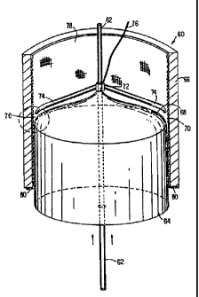
Figure 9 is a perspective, partially sectioned
view of an apparatus for use in practicing the method
of the present invention. The apparatus 60.comprises
a center guide shaft 62 with a cylindrical mandrel 64
disposed and axially movable thereon. The center
guide shaft 62 is centered with respect to the surface
of the cylindrical mandrel 64, coincides with the axis
thereof, and is oriented vertically.
The apparatus 6o also includes an outer cylinder
66, partially sectioned in Figure 9. The outer
cylinder 66 has an inner cylindrical surface, the
13
i
. CA 02239877 1998-06-08
__.
WO 98/15402 PCT/LTS97/I3794
center guide shaft 62 also being centered with respect
to this inner cylindrical surface and coinciding with
the axis thereof. Outer cylinder 66, as well as
._ cylindrical mandrel 64, may have smooth, polished
surfaces.
Cylindrical mandrel 64 is designed to be movable
along center guide shaft 62, and, having a smaller
radius than outer cylinder 66, to be disposable
therewithin. As cylindrical mandrel 64 and outer
cylinder 66 are coaxial on center guide shaft 62, a
uniformly thick space, having a thickness equal to the
difference between the radius of the cylindrical
mandrel 64 and the radius of the outer cylinder 66,
separates the cylindrical mandrel 64 and the outer
cylinder 66 when the former is within the latter.
Outer cylinder 66 is at least as long as cylindrical
mandrel 64, so that cylindrical mandrel 64 may be
completely disposed within the outer cylinder 66.
Cylindrical mandrel 64 has a curved nose 68,
which forms a convergirig geometry with outer cylinder
66 and defines a nip 70 therebetween.
Outer cylinder 66 may be an integral structure,
or may comprise two halves bolted together~and readily
separable from one another.
Above curved nose 68, and displaceable along
center guide shaft 62 therewith, is a polymeric resin
distribution manifold 72. The manifold 72 may
comprise one or more nozzles 74 for depositing a
polymeric resin material into the nip 70. The
polymeric resin distribution manifold 72 may take any
one of a number of forms, all of which are adapted to
provide a polymeric resin material to the nip 70
continuously about the circumference thereof. For
example, the manifold 72 may have a single or double
nozzle 74, as shown in Figure 9. Preferably, if this
14
CA 02239877 1998-06-08
t
WO 98/15402 PGT/tTS97/I3794
is the case, the nozzle or nozzles 74 are rotatable
about the center guide shaft 62- to provide a
continuous supply of polymeric resin material
completely about the circumference of the nip 70.
Alternatively, instead of individual nozzles 74, the
polymeric resin distribution manifold 72 could include
a stationary ring disposed above the nip 70 and having
multiple outlets, provided at fixed angular intervals
thereabout. In any event, the exact manner in which
the polymeric resin distribution manifold 72 supplies
polymeric resin material to the nip 70 is less
important than the requirement that the distribution
be uniform.
It will be noted that a conduit 76 supplies the
polymeric resin material to the distribution manifold
72 from some appropriate reservoir.
The apparatus 60 may also include a cover, not
shown in Figure 9, and a vacuum pump, so that the
volume within the outer cylinder 66 and above the
curved nose 68 may 'be placed under a negative
pressure, that is, a pressure below that outside the
outer cylinder 66, to facilitate the removal of air
bubbles from the polymeric resin material.
Having thus described the apparatus 60, we turn
now to the method by which a base fabric may be coated
and impregnated with a polymeric resin material to
provide a belt of the variety shown in Figures 2 and
5. More generally, the method to be first described
is suitable for placing a coating of a polymeric resin ,
material on the inside of an endless base fabric or on
the inside of a previously coated belt.
.Firstly, one provides an endless base fabric 78,
either woven endless or flat-woven and seamed into
endless form, having a length equal to that desired
for the finished belt and a width somewhat greater
,, CA 02239877 1998-06-08
WO 98/I5402 PCTlUS97/I3794
than that desired for the finished belt. It should be
understood that, instead of endless base fabric 78,
the base could be any other form of endless substrate
used by those in the industry.
The base fabric 78 is their disposed within an
outer cylinder 66 having a circumference at least
equal to the length of the base fabric 78, and,
preferably, a smooth, polished surface. The base
fabric 78 may be attached, or anchored, to the bottom
to of the outer cylinder 66 at points 80, and,
alternatively or in addition, may be attached at
points along the top of the outer cylinder. Base
fabric 78 may be placed under tension axially with
respect to outer cylinder 66.
The cylindrical mandrel 64 is then moved upward
along center guide shaft 62 into outer cylinder 66.
Once the nose 68 and cylindrical mandrel 64 are within
the outer cylinder 66 an amount sufficient to form nip
70, polymeric resin material is dispensed from nozzle
74.
Figure 10 is an enlarged view of the circled area
in Figure 9. Polymeric resin material 82 forms a pool
84 in nip 70 when dispensed from nozzle 74. The
upward motion of nose 68 and cylindrical mandrel 64 _
generates hydrostatic forces which drive the polymeric
resin material 82 into the base fabric 78, which drive
the base fabric 78 toward the outer cylinder 66, and
which drive the air, in the form of bubbles 86, out of
the base fabric 78 and pool 84. Bubbles 86 migrate to
the top of the pool 84 under the influence of gravity
and because of the vertical orientation of apparatus
60. The upward migration and removal of bubbles 86
can be facilitated by placing the interior of the
outer cylinder 66 under a sl.i.ght vacuum, as discussed
above.
16
CA 02239877 1998-06-08
WO 98/15402 PCT/L1597/I3794
- The process illustrated in Figure 10 proceeds
until cylindrical mandrel 64 is completely within
outer cylinder 66, yielding a belt, like those shown
in Figures 2 and 5, of thickness t equal to the
separation between cylindrical mandrel 64 and outer
cylinder 66, that separation being the difference
between the radii thereof.
At this point, before the removal of the belt
from the apparatus 60, the polymeric resin material 82
l0 may be totally cured. Then, the belt, still on the
cylindrical mandrel 64, may be removed from the outer
cylinder 66, preferably by using an outer cylinder
. separable into segments. Finally, the belt may be
removed from cylindrical mandrel 64 according to any
one of the conventional techniques used by those
skilled in the art for this purpose, such as by
supplying compressed air into the interface between
the belt and the cylindrical mandrel 64.
Alternatively, before the removal of the belt
from the apparatus 60, the polymeric resin material 82
may be only partially cured, that is, B-staged or
green staged, to leave bonding sites for additional
coating material on either side (inside or outside) of
the belt.
If an additional coating layer on the inside of
the belt is desired, the belt is removed from the
cylindrical mandrel 64, and redisposed within the
outer cylinder 66, as above. Then a new cylindrical
mandrel 64 of smaller radius than that previously used
is disposed on center guide shaft 62, and the inside
of the belt coated according to the process previously
described. Once the additional coating layer of
polymeric resin material 82 has been applied across
the width of the belt, that is, when cylindrical
mandrel 64 is completely within outer cylinder 66, the
17
CA 02239877 1998-06-08
_.,
WO 98/15402 PCT/US97/I3794
coating may be totally cured, or partially cured,
where an additional coating layer or layers is to be
applied to either side of the belt. In either event,
it will again be necessary to remove the belt from the
cylindrical mandrel 64.
As mentioned above, it may be desirable to place
a layer of polymeric resin material 82 on the outside
of the belt, as well as on the inside, to ensure that
the belt's neutral axis of bending coincides with the
IO base fabric. Where such a layer is provided, it may
be provided with grooves, blind holes, indentations or
the like to provide for the temporary storage of water
pressed from fibrous web 20 in the press nip l0.
Figure 11 is a view, analogous to that provided
in Figure 10, for the situation where a coating is
being applied to the outside of a previously coated
belt structure .
Belt 88 in Figure 1.1 is one having at least one
layer of polymeric resin material on its inside and
having a totally impregnated base fabric. It is
disposed on an outer cylinder 66 of slightly greater
radius than that used during the coating of its
inside, and attached or anchored to the bottom of
outer cylinder 66 at points 80, as shown in Figure 9.
Belt 88 is then bunched up over nose 68 and beneath
nozzles 74, so that nozzles 74 may deposit polymeric
resin material 82 in a pool 84 between outer cylinder
66 and the outside of belt 88, where a nip .90 is
formed therebetween. Cylindrical mandrel 64, having
a radius equal to that used to provide the coating on
the inside of belt 88, or having a radius equal to the
last one used if more than one coating layer has been
applied to the inside of the belt 88, is then forced
upward into belt 88 and outer cylinder 66 to carry out
the coating process in a manner similar to that
18
CA 02239877 1998-06-08
WO 98/15402 PCTIUS97/13794
previously described. Hydrostatic forces, generated
by the upward motion of nose 68 and cylindrical
mandrel 64, drive the air, which may be trapped in the
pool 84 of polymeric resin material 82 in~the form of
bubbles 86, upward and out of the pool 84.
As before, bubbles 86 migrate to the top of pool
84 under the influence of gravity and because of the
vertical orientation of apparatus 60, and the upward
migration and removal of bubbles 86 can be facilitated
l0 by placing the interior of the outer cylinder 66 under
a slight vacuum, as discussed above.
The process illustrated in Figure 11 proceeds
until cylindrical mandrel 64' is completely within
outer cylinder 66, yielding a belt of thickness t'
equal to the separation between cylindrical mandrel 64
and outer cylinder 66, that separation being the
difference between the radii thereof.
At this point, before the removal of belt 88 from
apparatus 60, the polymeric resin material may be
totally cured. Then, the belt 88, still .on
cylindrical mandrel 64, may be removed from outer
cylinder 66. With belt 88 still on cylindrical
mandrel 64, grooves 38, blind holes 46, as shown in
Figures 3, 4, 7 and 8, or some other indentations or
surface features may be provided on the outside
thereof by graying, drilling or the like.
Alternatively, these surface features may be
provided on the outside surface of belt 88 by using an
outer cylinder 66 having corresponding features on its
inner cylindrical surface in the final coating step
for the outside of the belt 88. For example, as shown
in Figure 12, outer cylinder 66 may have an inner
surface having circumferential grooves 92 which will
ultimately mold grooves 38 in the outer surface 36 of
belt 32 of Figures 3 and 7. Further, as shown in
19
CA 02239877 1998-06-08
.J
WO 98/15402 PCT/US97/13794
' . Figure 13, outer cylinder 66 may have an inner surface
having a plurality of cylindrical members 94 which
will ultimately mold blind holes 46 in the outer
surface 44 of belt 40 of Figures 4 and ~8. Either
feature, circumferential grooves 92 or cylindrical
members. 94 may also be provided by lining the outer
cylinder 66, that is, by covering the inner surface of
outer cylinder 66, with a liner bearing the
appropriate surface characteristics.
Figure 14 is a view, analogous to that provided
in Figure 10, for the situation where the outer
cylinder 66 has an inner surface with circumferential
grooves 92. Polymeric resin material 82 forms a pool
84 in nip 70 when dispensed from nozzle 74. Again,
the upward motion of nose 68 and cylindrical mandrel
64 generates hydrostatic forces which drive the
polymeric resin material 82 into the base fabric 78
and into circumferential grooves 92, which drive the
base fabric 78 toward the outer cylinder 66, and which
drive the air, in the form of bubbles 86, out of the
base fabric 78 and pool 84.
As before, bubbles 86 migrate to the top of pool
84 under the influence of gravity and because of the
vertical orientation of apparatus 60, and the upward
migration and removal 'of bubbles 86 can be facilitated
by placing the interior of the outer cylinder 66 under
a slight vacuum, as discussed above. .
The process illustrated in Figure 14 proceeds
until cylindrical mandrel 64 is completely within
outer cylinder 66, yielding a belt of overall
thickness t" equal to the separation between
cylindrical mandrel 64 and the bottoms of
circumferential grooves 92, and with grooves of a
depth equal to that of circumferential grooves 92.
The polymeric resin material 82 is cured, and the
20 _
CA 02239877 1998-06-08
WO 98!15402 PGT/US97/I3794
outer cylinder 66 separated into segments to remove
the newly produced belt on cylindrical mandrel 64.
Finally, the belt may be removed _from cylindrical
mandrel 64 according to any one of the conventional
techniques used by those skilled in the art for this
purpose.
Alternatively, before the removal of the belt 88
from the apparatus 60, the polymeric resin material 82
may be only partially cured, to leave bonding sites
l0 for additional coating material on either side of the
belt . Total curing should only be effected when no
further layers of coating material (polymeric resin
' material 82) are to be applied to either side of the
belt, as, at such time, there would be no further need
to preserve bonding sites for additional coating
layers. An additional coating layer may be provided
on the outside of the belt 88, and the additional
coating layer provided with surface features, such as
grooves or blind holes, in one of the manners just
described.
When the belt has been built up to its final
desired thickness following the total impregnation of
the base fabric with the polymeric resin material and
the provision of a coating layer or layers on the
inside or both sides thereof, the polymeric resin
material is totally cured. Then the belt, still on
cylindrical mandrel 64 , is removed from outer cylinder
66. While still on cylindrical mandrel 64, grooves
38, blind holes 46 or the like may be provided on the
outside of the belt, if they have not already been
provided by corresponding features on the inside
cylindrical surface of the outer cylinder 66. In
addition, the outside of the belt may also be ground
to provide it with a uniform thickness and a
particular surface finish. Finally, the edges of the
21
CA 02239877 1998-06-08
WO 98/15402 PCT/US97/13794
belt may be trimmed to remove peripheral,
unimpregnated portions of the base fabric, and to
provide the belt with a final desired width.
. The method just described achieves the intended
goals of total impregnation of the base fabric ~ with
the polymeric resin material being used and the
removal of all air from the structure thereof. In
addition, the method enables one to provide the inner
surface of the belt with a layer of polymeric resin
l0 material without having to invert the belt at any time
during the manufacturing process.
The removal of all air from the structure of the
base fabric is facilitated by the vertical orientation
of apparatus 60, and by the use of a cover on the
outer cylinder 66, and a vacuum pump to reduce the air
pressure within the outer cylinder 66. The reduction
in air pressure draws the air bubbles out of the
polymeric resin m~~terial. The apparatus 60 may,
however, be disposed horizontally, but, if so
disposed, must be rotated about center guide shaft 62
to insure that pool 84 of polymeric resin material 82
remains uniformly distributed about the circumference
of nip 70 and does not pool at the bottom of the
horizontally disposed apparatus 60.
The resins used as polymeric resin material 82
are preferably of the reactive type, either chemically
cross-linked with a catalyst or cross=linked with the
application of heat. Resins having a lDO~s solids
composition, that is, lacking a solvent, are
preferred, as solvents tend to generate bubbles during
the curing process. Polyurethane resins having 100~c
solids compositions are preferred. It should be
understood, for example, that the two sides of the
belt may be coated with the same or a different 100
solids resin composition, and that there is no
22
CA 02239877 1998-06-08
WO 98/15402 PCT/US97/I3~94
requirement that both sides of the belt be coated with
a single type of 100% solids resin composition.
Because the polymeric resin material 82 will tend
to stick to the cylindrical mandrel 64,~ it may be
desirable to provide the cylindrical mandrel 64 with
a sleeve or coating which would enable it to slide
more readily with respect to the inside of the coated
belt. The sleeve or coating would also make it easier
to remove the coated belt from the cylindrical mandrel
l0 64 at the appropriate time. Polyethylene or
tetrafluoroethylene (TEFLONm) may be used as the
coating or sleeve.
Modifications to the above would be obvious to
those of ordinary skill in the art, but would not
bring the invention so modified beyond the scope of
the appended claims.
23