Language selection

Search

Patent 2240059 Summary

Third-party information liability

Some of the information on this Web page has been provided by external sources. The Government of Canada is not responsible for the accuracy, reliability or currency of the information supplied by external sources. Users wishing to rely upon this information should consult directly with the source of the information. Content provided by external sources is not subject to official languages, privacy and accessibility requirements.

Claims and Abstract availability

Any discrepancies in the text and image of the Claims and Abstract are due to differing posting times. Text of the Claims and Abstract are posted:

  • At the time the application is open to public inspection;
  • At the time of issue of the patent (grant).
(12) Patent: (11) CA 2240059
(54) English Title: INTELLIGENT CHARGE ALTERNATOR
(54) French Title: ALTERNATEUR INTELLIGENT
Status: Expired and beyond the Period of Reversal
Bibliographic Data
(51) International Patent Classification (IPC):
  • H02J 7/16 (2006.01)
  • H02K 19/34 (2006.01)
  • H02M 7/10 (2006.01)
(72) Inventors :
  • DURELLI, OLINDO LUCA JULIO (Argentina)
(73) Owners :
  • OLINDO LUCA JULIO DURELLI
(71) Applicants :
  • OLINDO LUCA JULIO DURELLI (Argentina)
(74) Agent: GOWLING WLG (CANADA) LLP
(74) Associate agent:
(45) Issued: 2000-10-24
(22) Filed Date: 1998-06-09
(41) Open to Public Inspection: 1998-12-10
Examination requested: 1998-06-09
Availability of licence: Yes
Dedicated to the Public: N/A
(25) Language of filing: English

Patent Cooperation Treaty (PCT): No

(30) Application Priority Data:
Application No. Country/Territory Date
P97 01 02504 (Argentina) 1997-06-10

Abstracts

English Abstract


An intelligent charge alternator is disclosed and is adapted to operate with
two or more batteries which are individually charged, alone or connected in
series. In each stator slot there are 2, 3, 4, etc., windings in parallel and each
coil is independent to the other. It requires a rectifier bridge for each coil in
parallel, either star, triangle, diphase, or single-phase winding and can be
connected in series. The batteries can also be connected individually or in series
between negative positive negative pole, etc., adding in this case the voltages, but
it will charge the discharged battery in amperes and it will not charge the charged
battery with over potential.


French Abstract

Alternateur intelligent pouvant fonctionner avec deux batteries ou plus, lesquelles sont chargées individuellement et raccordées individuellement ou en série à l'alternateur. Chaque encoche du stator loge au moins 2 bobinages en parallèle, chacun des enroulements étant autonome. Le dispositif nécessite un support de diodes pour chaque enroulement monté en parallèle, soit en étoile, en triangle, biphasé ou monophasé, et peut être raccordé en série. Les batteries peuvent également être raccordées individuellement ou en série, entre pôles négatif, positif, négatif, etc. Les tensions sont ainsi additionnées et chargent les batteries déchargées sans toutefois surcharger celles qui le sont déjà.

Claims

Note: Claims are shown in the official language in which they were submitted.

I CLAIM:
1. A charging alternator for charging two or more batteries; said
alternator comprising at least two windings, said windings being either star,
triangle
or mono-phase; said at least two windings being parallel and located in the
same slot;
each coil in the same slot having the same number of turns to thereby obtain
the same
voltage.
2. A charging alternator for charging two or more batteries; said
alternator comprising at least two windings, each of said at least two
windings being
either a star, a triangle or a monophase; said at least two windings being
connected in
parallel and located in the same slot of a single stator; and all windings in
the same
slot having an equal number of turns to thereby obtain an equal voltage.
3. A charging alternator for charging two or more batteries individually
or connected in series, said alternator comprising one rotor and one stator
and with at
least two parallel windings in each slot of said stator, said windings being
arranged in
a star, a triangle, or a monophase for each one of said batteries used; said
at least two
windings being connected in parallel and located in the same slot of said
stator and all
windings in the same slot having an equal number of turns to thereby obtain an
equal
voltage; two rectifier plates with three positive diodes and three negative
diodes in
each one, placed in between the parallel windings and each winding plate
connected
in series; two rectifier bridges connected to the respective bridges of
batteries and
auxiliary diodes to feed said rotor.
4. A charging alternator according to claim 3 wherein the rectifier plates
are connected in parallel or in series-parallel.
-6-

Description

Note: Descriptions are shown in the official language in which they were submitted.


CA 022400F79 1998-06-09
INTELLIGENT CHARGE ALTERNATOR
FIELD OF THE INVENTION
The present invention relates to electrical energy generators, and more
specifically to alternators capable of non-destructive batter,v charging.
Background of the Invention
In equipment such as tractors, buses, road machinery, aircraft and the like
there are AM-FM radios, telephones, BLU, BHF, fans, cassette-players all of
which require 12 volts to operate. Often, such equipment is connected to one or
more 12 volt batteries, which in turn are connected to an alternator.
In conventional 24/28 volt alternators, 24 volts is for two batteries of 12
volts discharged and 28 volts with all its limited charge. A voltage regulator
stops this voltage which is 14 volts or 28 volts depending on the alternator
design. A problem which exists in conventional alternators is that, in two battery
equipment of 12 volts+12 volts (under rest or discharged) and 14 volts+14 volts
in the case of its full charge, as in the example above, the equipment is
connected to the first battery, then nothing can be connected to the second 12-24
volt battery. This is because at least one of the equipment pieces would burn out
since it would have a 12 volts potential to ground. That is to say, the 0-12 volt
battery consumes current to feed all this equipment, thus lowering the potential to
less than 12 volts until it is completely discharged.
Therefore, in a conventional system a start would be difficult or nill since,
although the 12-24 volt battery is completely charged, the 0-12 volt battery is
not. The 0-12 volt battery lowers its potential until 0, so that it does not start. If
it would, the following process would take place: the 0-12 volt battery would
remain at 12 volts and the 12-24 volt battery, the last one at its full charge, one

CA 022400~9 1998-06-09
would increase up to 15 or 16 volts, totalling 28 volts; the regulator would close
and it would not charge the 0-12 volt battery.
To sum up, the 0-12 volt battery is destroyed due to the lack of slllf~tin~
charge and the 12-24 volt battery is destroyed by overvoltage, water depletion for
S excessive potential and also by overheating. In a 24 volt conventional system,
where sometimes a starter, alternator and 24 volt lights are used, such problemsoccur with the use of 12 volt equipment, and others have a device called parallel-
series. This one is frequently out of work, leaving the machine without starter
and battery, causing serious problems in the end.
Summary of the Invention
An object of the present invention is to provide means in the form of an
intelligent charge alternator, to fully charge at least one discharged battery while
not over charging any other battery that is fully charged, thus not ~1~m~gin~ the
charged batteries.
To accomplish this object, the intelligent charge alternator of the present
invention is provided with two or more coil windings; wherein the coil windings
are star, triangle or mono-phase windings, and wherein the coil windings are in
parallel, the coil windings in the same slot, and the coil windings in each slothave the same number of turns thus obtaining the same voltage.
According to a broad aspect, the invention relates to a charging alternator
for charging two or more batteries. The alternator comprises at least two
windings, the windings being either star, triangle or mono-phase in form and theat least two windings being parallel and located in the same slot. Each coil in
the same slot has the same number of turns to thereby obtain the same voltage.
Brief Description of the Drawings
These and other features of the invention will become more apparent from
the following description in which reference is made to the appended drawings inwhich:
-2-

. . CA 022400~9 1998-06-09
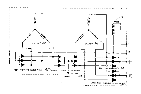
Figure 1 is a diagram of series connection according to the invention;
Figure 2 is a diagram of parallel connection;
Figure 3 is an exploded view of the intelligent charge alternator of the
invention; and
S Figure 4 is a table of poles for the alternator.
Detailed Description of Preferred Embodiments of the Invention
Referring to Figures 1 and 2 the alternator of the invention has star,
triangle or monophase windings. The windings are realized in parallel, and as
many parallel windings are provided as batteries in use, and are independent
among the parallel coils. Each winding has its own plate rectifier with three
positive diodes 40 and three negative diodes 30, totalling six diodes. Therefore,
two windings will have two rectifier bridges; three windings will have three
rectifier bridges, four windings will have four rectifier bridges and so on. Thealternator of the invention may be used with at least the following battery
connections: 12 volts+12 volts, 24 volts+24 volts, 7 volts+7 volts or 24 volts+12
volts+6 volts. By way of example, it is preferred to design 12 volts+l2 volts+6
volts+24 volts. The first battery is connected to a parallel winding with six wire
turns, the second battery is connected to a winding with six turns, the third
battery is connected to a winding with three turns and the last battery, which is
24 volts, is connected to a winding with twelve turns. All windings have
individual rectifiers connected in series, -12+-12-6+-24+= 54 volts. In the charge
mode, the voltages would rise to the following values 14+14+7+28, all uniform.
The batteries are connected in series or parallel to the rectifier bridges.
Figure 1 shows a scheme of a series connection and Figure 2 shows a scheme of
parallel connection. The batteries may have a different current, the one with less
current will receive the corresponding charge until its complete charge, being
either a 12 volt battery and 35 amperes or up to more than 220 amperes. In this
case the complete charge is delayed a bit more; the values in voltage are strict 6-
7 volts for 6-7; of 12-14 volts for 12/14 batteries, according to the winding of
r
-3 -

CA 022400~9 1998-06-09
stator 20 with regard to the voltage. But current varies according to the needs at
the start or the amount of current used. In each positive/negative joint of the plate
rectifier there is a bridge connected to the respective bridge of the corresponding
battery, according to plane of the stator 20, two parallel windings and two
rectifier plates bridge connected in series but parallel bridge rectifier with
batteries.
If the first battery is discharged and the other batteries are charged, the
alternator of the invention will fully charge the discharged battery, and the
charged batteries will not receive any current because it is not necessary. In this
case we would use a 24 volt to 28 volt regulator to stop. The rotor 10 feeding
that would be 24/28, from the second bridge with three diodes or feed it with the
start key as with any other conventional alternator. An alternator can be
designed 12/14/12/14, which is used frequently, but with binding posts the
bridges can be connected in parallel, i.e. 12/14, and thus double the current. If in
24/28 the current would be around 100 amperes or more, after that it would be
200 or more, but the intelligent charge alternator according to the invention aims
to solve the aforementioned problem with regards to the equipment using 0-12
volts. It may be the case when all the batteries are discharged, this alternator will
charge all of them until fully complete, that is 14-7, 28 volts or 14+14 as in the
last case.
The rotor 10, Figure 3, is conventional, but we must take into account the
voltage to use. The most common one is 12/14 volts or 24/28 volts, the last one
being the best one to solve the problem mentioned above. The regulators are the
most conventional ones, such as, 12/14 volts or 24/28 volts. The stator 20 is also
conventional, or having certain adjustments if necessary. The cover on the
collector side is lengthened to house 2-3-4, etc. rectifiers or it can be designed to
house half of them on the pulley side cover and the other half on the collector
s1de cover.
Figure 3 shows an exploded view of the intelligent charge alternator of the
invention. The order of assembly is as follows: female screw 100, grover washer
-4 -

. CA 022400~9 1998-06-09
102, double pulley 104, turbine 106, rear cover 108, spacer 110, bearing 112,
spacer 114, axle box 116, rotor 10, spacer 120, bearing 122, bearing 124,
collector 126, front cover 128, small cover 130, brushes 132, and cover 134.
The windings can be aluminium, copper, silver, superconductives, or other
like material.
Regulators should have enough capacity for the design and current
consumption of the rotor 10.
An alternator can be designed for two or more batteries with the poles as
shown in Figure 4.
The rotor 10 can also be fed by +B without the three auxiliary diodes 50.
The rotor 10 can be conventional and the most convenient one, the same with the
voltage 6/7, 12/14, 24/28 volts. The stator 20 is the same as the conventional
type, but it can be designed for numbers of revolutions, current, its winding,
slots, according to the requirements, the collector side cover is lengthened to
house the diode bridges being 2-3-4 etc., and the pulley side cover can also be
lengthened and house there half of the rectifier bridges.
The intelligent charge alternator according to the invention can be used for
the construction of either high or low energy production alternators.
While the invention has been described in connection with a specific
embodiment thereof and in a specific use, various modifications thereof will
occur to those skilled in the art without departing from the spirit and scope of the
invention as set forth in the appended claims.
The terms and expressions which have been employed in this specification
are used as terms of description and not of limitations, and there is no intention
in the use of such terms and expressions to exclude any equivalents of the
features shown and described or portions thereof, but it is recognized that various
modifications are possible within the scope of the invention claims.

Representative Drawing
A single figure which represents the drawing illustrating the invention.
Administrative Status

2024-08-01:As part of the Next Generation Patents (NGP) transition, the Canadian Patents Database (CPD) now contains a more detailed Event History, which replicates the Event Log of our new back-office solution.

Please note that "Inactive:" events refers to events no longer in use in our new back-office solution.

For a clearer understanding of the status of the application/patent presented on this page, the site Disclaimer , as well as the definitions for Patent , Event History , Maintenance Fee  and Payment History  should be consulted.

Event History

Description Date
Inactive: IPC from MCD 2006-03-12
Time Limit for Reversal Expired 2003-06-09
Letter Sent 2002-06-10
Publish Open to Licence Request 2001-05-25
Grant by Issuance 2000-10-24
Inactive: Cover page published 2000-10-23
Pre-grant 2000-07-18
Inactive: Final fee received 2000-07-18
Letter Sent 2000-06-16
Amendment After Allowance Requirements Determined Compliant 2000-06-16
Amendment After Allowance (AAA) Received 2000-05-23
Inactive: Amendment after Allowance Fee Processed 2000-05-23
Letter Sent 2000-01-18
Notice of Allowance is Issued 2000-01-18
Inactive: Approved for allowance (AFA) 1999-12-10
Application Published (Open to Public Inspection) 1998-12-10
Classification Modified 1998-09-24
Inactive: First IPC assigned 1998-09-24
Inactive: IPC assigned 1998-09-24
Filing Requirements Determined Compliant 1998-08-19
Inactive: Filing certificate - RFE (English) 1998-08-19
Application Received - Regular National 1998-08-18
Request for Examination Requirements Determined Compliant 1998-06-09
All Requirements for Examination Determined Compliant 1998-06-09

Abandonment History

There is no abandonment history.

Maintenance Fee

The last payment was received on 2000-05-26

Note : If the full payment has not been received on or before the date indicated, a further fee may be required which may be one of the following

  • the reinstatement fee;
  • the late payment fee; or
  • additional fee to reverse deemed expiry.

Please refer to the CIPO Patent Fees web page to see all current fee amounts.

Fee History

Fee Type Anniversary Year Due Date Paid Date
Application fee - small 1998-06-09
Request for examination - small 1998-06-09
2000-05-23
MF (application, 2nd anniv.) - small 02 2000-06-09 2000-05-26
Final fee - small 2000-07-18
2001-05-25
MF (patent, 3rd anniv.) - small 2001-06-11 2001-05-25
Owners on Record

Note: Records showing the ownership history in alphabetical order.

Current Owners on Record
OLINDO LUCA JULIO DURELLI
Past Owners on Record
None
Past Owners that do not appear in the "Owners on Record" listing will appear in other documentation within the application.
Documents

To view selected files, please enter reCAPTCHA code :


To view images, click a link in the Document Description column. To download the documents, select one or more checkboxes in the first column and then click the "Download Selected in PDF format (Zip Archive)" or the "Download Selected as Single PDF" button.

List of published and non-published patent-specific documents on the CPD .

If you have any difficulty accessing content, you can call the Client Service Centre at 1-866-997-1936 or send them an e-mail at CIPO Client Service Centre.


Document
Description 
Date
(yyyy-mm-dd) 
Number of pages   Size of Image (KB) 
Claims 1998-06-09 1 9
Drawings 1998-06-09 4 76
Abstract 1998-06-09 1 17
Description 1998-06-09 5 228
Cover Page 1998-12-16 1 46
Cover Page 2000-09-21 1 47
Representative drawing 1998-12-16 1 9
Claims 2000-05-23 1 39
Representative drawing 2000-09-21 1 10
Filing Certificate (English) 1998-08-19 1 174
Commissioner's Notice - Application Found Allowable 2000-01-18 1 166
Reminder of maintenance fee due 2000-02-10 1 113
Maintenance Fee Notice 2002-07-08 1 177
Correspondence 2000-07-18 1 28
Fees 2000-05-26 1 28
Correspondence 2001-05-25 1 25
Fees 2001-05-25 1 35