Note: Descriptions are shown in the official language in which they were submitted.
CA 02240303 1998-06-11
-1-
Description
RETRACTABLE SPEAKER ASSEMBLY FOR A PARTITION
Field of Invention
This invention relates generally to audio speakers, and more specifically to a
retractable speaker assembly for a partition.
Background of Invention
Audio speaker systems have traditionally been mounted or installed into homes
so that the audio speaker systems and specifically the speaker are visible to
the occupants
of the room. Since the speaker size is often significant, an ability to
conceal the speaker
so as to improve the overall appearance of the room would be desirable.
Prior art audio speaker systems for a room and for an automobile have tried to
address some of the aforenoted problems.
United States Patent No. 5,321,760 issued on June 14, 1994 to Davidson Textron
Inc. of Dover, New Hampshire by assignment from the inventor John D. Gray.
This
patent relates to a housing in which is mounted a speaker. The housing is
mounted on
a platform which is attached by trunnions to corresponding mounts. Mounts are
secured
to an automobile window ledge that extends between a rear seat and a rear
window of the
automobile, the housing is capable of rotation about an axis extending through
the center
of trunnions. Operation of actuator in the clockwise direction causes
platform, and thus
housing, to rotate upwards about axis from the retracted position to the
extended position.
Sideways rotation of housing is achieved by an actuator mounted on the topside
of
platform.
United States Patent No. 5,285,501 issued on February 8, 1994 to the inventor
Harry A. Castillo. This patent relates to an arcuate speaker which is arranged
for pivotal
mounting relative to a vehicular rear shelf plate in operative communication
with a cover
CA 02240303 1998-06-11
-2-
plate, wherein pivoting of the speaker in communication with a bottom surface
of the rear
shelf plate effects pivotal displacement of the cover plate for audible access
of the speaker
relative to an associated passenger compartment of the vehicle.
United States Patent No. 4,932,032 issued to Mark A. Nuernberger on May 8,
1990. This patent relates to a ceiling panel sound system having a completely
self-
containing high fidelity speaker system that is installed in a supporting
grillwork for a
suspended ceiling. The speakers are installed in a rectangular mounting panel
having a
shape that corresponds to the ceiling tile.
United States Patent No. 5,574,796 was issued on November 12, 1996 to Bose
Corporation of Farmingham, Massachusetts. This patent relates to a mount for
mounting
a loudspeaker in a room boundary structure having an outside surface away from
the
inside of the room which includes a frame constructed and arranged to rest on
the outside
surface. A spring has a first end attached to the frame and a free second end.
The
spring is constructed and arranged to exert a unidirectional force toward the
outside
surface whenever the second end of the spring is displaced from the outside
surface
toward the inside of the room.
Daniel N. Green, the inventor, assigned United States Patent No. 4,891,842
which
issued on January 2, 1990 to Posh Diversified Inc. of Oregon. This patent
relates to an
assembly for mounting a loudspeaker in a ceiling including a layer of sheet
material, said
assembly comprising: a mounting plate having an inner edge defining a circular
opening;
a circular ring extending down from the inner edge of said plate around said
opening for
forming an abutment to said sheet material of said ceiling; a recessed
circular shoulder
extending inward from the inner edge of said plate around said opening for
mounting a
loudspeaker in said opening; and a cover plate for covering said opening in
said mounting
plate, said cover plate including a screen and adapted for being removably
mounted onto
said circular ring in said mounting plate.
CA 02240303 1998-06-11
-3-
Summary of the Invention
The object of one aspect of the invention is to provide an improved
retractable
speaker assembly for installation in a partition.
In accordance with one aspect of the invention there is provided a retractable
speaker assembly for a partition having a housing, a cavity, and actuator and
a panel
where the housing is retractable from a first closed position to a second
operable position
by the actuator. The partition may conceal the housing when the speaker
assembly is in
the first closed position. In the second operable position the housing is
exposed. The
panel is associated with the housing in such a way that the cavity is closed
when the
housing is in the first closed position.
In accordance with yet another aspect of the invention, there is provided a
retractable speaker assembly for a ceiling having a housing, a cavity, and
actuator and
a panel where the housing is retractable from a first closed position to a
second operable
position by the actuator. The ceiling may conceal the housing when the speaker
assembly
is in the first closed position. In the second operable position the housing
is exposed.
The panel is associated with the housing in such a way that the cavity is
closed when the
housing is in the first closed position.
In accordance with still another aspect of the invention, there is provided a
retractable speaker assembly further comprising a pivot means such that the
panel is
retractable relative to the partition by the pivot means.
In accordance with a further aspect of the invention, there is provided a
retractable
speaker assembly where the actuator is a rack and pinion means.
An advantage of the present invention over the prior art is that the speaker
assembly is retractable into the partition and concealed by the panel when the
system is
not operating, yet the speaker assembly is then visible and oriented for
optimum sound
when the system is in the second operable position.
CA 02240303 1998-06-11
-4-
Brief Descr~tion of Drawings
A detailed description of the preferred embodiments are provided herein below
by way of example only and with reference to the following drawings, in which:
Fig. la-d, in perspective views, illustrate a retractable speaker assembly for
a
partition, in operation, in accordance with a preferred embodiment of the
present
invention.
Fig. 2a-b, in cross-sectional front views, illustrate a retractable speaker
assembly
for a partition, in operation, in accordance with a preferred embodiment of
the present
invention.
Fig. 3a-b, in cross-sectional side views, illustrate a retractable speaker
assembly
for a partition, in operation, in accordance with a preferred embodiment of
the present
invention.
Fig. 4a-b, in cross-sectional side views, illustrate a retractable speaker
assembly
for a partition, in operation, in accordance with a preferred embodiment of
the present
invention.
Fig. 5a-b, in cross-sectional side views, illustrate a retractable speaker
assembly
for a partition, in operation, in accordance with a preferred embodiment of
the present
invention.
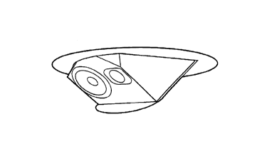
Fig. Sc, in a perspective view, illustrate a retractable speaker assembly for
a
partition, in accordance with a preferred embodiment of the present invention.
Fig. 6a-b, in cross-sectional side views, illustrate a retractable speaker
assembly
for a partition, in operation, in accordance with a preferred embodiment of
the present
invention.
CA 02240303 1998-06-11
-5-
Fig. 7a-b, in cross-sectional side views, illustrate a retractable speaker
assembly
for a partition, in operation, in accordance with a preferred embodiment of
the present
invention.
Fig. 8a-b, in cross-sectional side views, illustrate a retractable speaker
assembly
for a partition, in operation, in accordance with a preferred embodiment of
the present
invention.
Fig. 9a-b, in cross-sectional side views, illustrate a retractable speaker
assembly
for a partition, in operation, in accordance with a preferred embodiment of
the present
invention.
Fig. l0a-b, in cross-sectional side views, illustrate a retractable speaker
assembly
for a partition, in operation, in accordance with a preferred embodiment of
the present
invention.
Fig. lla-b, in cross-sectional side views, illustrate a retractable speaker
assembly
for a partition, in operation, in accordance with a preferred embodiment of
the present
invention including a movable lighting means.
Fig. 12a-b, in cross-sectional side views, illustrate a retractable speaker
assembly
for a partition, in operation, in accordance with a preferred embodiment of
the present
invention including a stationary lamp.
Fig. 13, in a cross-sectional side view, illustrates a retractable speaker
assembly
for a partition, by manual operation, in accordance with a preferred
embodiment of the
present invention.
In the drawings, preferred embodiments of the invention are illustrated by way
of example. It is to be expressly understood that the description and drawings
are only
for the purpose of illustration and as an aid to understanding, and are not
intended as a
definition of the limits of the invention.
CA 02240303 1998-06-11
-6-
Best Mode for Carrying Out the Invention
In the description which follows, like parts are marked throughout the
specification and the drawings with the same respective reference numerals.
The
drawings are not necessarily to scale and in some instances proportions may
have been
exaggerated in order to more clearly depict certain features of the invention.
Referring to Fig. la-d, 2a-b and 3a-b, there is illustrated a retractable
speaker
assembly 10 for a partition 12 in accordance with a preferred embodiment of
the
invention. The retractable speaker assembly 10 for a partition 12 includes a
housing 14,
a cavity 16, an actuator 18 and a panel 20. The housing 14 may be retractable
or
displaceable from a first closed position to a second operable position by the
actuator 18.
In the first closed position, the housing 14 is concealed by the partition 12
and the panel
20, whereas the housing 14 is exposed in a second operable position. The panel
20 is
associated with the housing 14 so that the cavity 16 where the retractable
speaker
assembly 10 is inserted and installed, is concealed or closed when the housing
14 is in
the first closed position. The housing 14 may be further defined as a speaker
28 and a
platform 30. The platform 30 may be structured so that it can rotate with the
speaker 28
about a pivot means 22.
The panel 20 which is associated with the housing 14 may be retractable or
displaceable to the partition 12 by the pivot means 22. The pivot means 22 may
be a
hinge. The partition 12 may be a ceiling or wall of a room.
In operation as shown in Fig. 1 through 10, the retractable speaker assembly
10
is resting in the first closed position, wherein the housing 14 is concealed
by the panel
20 and the partition 12. Upon the activation of the retractable speaker
assembly 10, the
housing 14 moves to the second operable position by the actuator 18. The pivot
means
22 allows for the housing 14 to be displaceable or retractable relative to the
partition 12
when the housing 14 moves from the first closed position to the second
operable position.
The panel 20 may extend beyond the housing 14 so as to conceal the cavity 16.
CA 02240303 1998-06-11
_7_
The installation of the retractable speaker assembly 10 may include defining a
cavity 16 between two joists 26, for the insertion of the retractable speaker
assembly 10.
The retractable speaker assembly 10 may be secured into the partition 12 or
ceiling by
fasteners (not shown). The retractable speaker assembly 10 may be installed at
such an
angle so as to provide optimum sound when in operation.
The actuator 18, as shown through Fig. 1 - 10 may be one of the following, but
not limited to: a rack and pinion means 32, telescoping means 34, a bellows
mechanism,
a pneumatic piston mechanism, a scissor means 36, or a ratchet mechanism 38.
The
actuator 18 may include an electric motor (not shown) thereby moving said
retractable
assembly 10 from a first closed position to a second operable position. In
Fig. 4a-b and
7a-b, the pivot means 22 may be associated with the housing 14 and the
internal structure
of the partition 12 thereby allowing the housing 14 to rotate about the pivot
means 22
moving the retractable speaker assembly 10 between a first closed position to
a second
operable position.
Referring to Fig. 1 - 13, the retractable speaker assembly 10 may include a
lightening means 40. The lightening means 40 may be mounted on to the panel 20
so
that when the retractable speaker assembly 10 is in the first closed position,
the lighting
means 40 is visible to occupants of the room. When the retractable speaker
assembly 10
is activated into the second operable position, the lighting means 40 is
rotated up into the
cavity 16, and the speaker 28 is visible to the occupants of the room. The
lighting means
40 may be activated and deactivated by a mercury switch 50. The lighting means
40,
such as a florescent tube light, may also be mounted to the partition 12 so
that it is
stationary when the speaker 28 moves between the first closed position and the
second
operable position.
Referring to Fig. 13, the retractable speaker assembly 10 may be movable from
the first closed position to the second operable position by manually rotating
or tilting the
housing 14 so that the panel 20 is concealed by the cavity and the speaker 28
is exposed
to the occupants of the room. The retractable speaker assembly 10 may rotate
360°
about the pivot means 22.
CA 02240303 1998-06-11
_g_
Various embodiments of the invention have now been described in detail. Since
changes in and/or additions to the above-described best mode may be made
without
departing from the nature, spirit or scope of the invention, the invention is
not to be
limited to said details.