Note: Descriptions are shown in the official language in which they were submitted.
~
.° i'~'~ CA 02240308 1998-06-11
~. c .
GATE VAhVE
BACKGROUND AND SUMMARY OF THE INVENTION '
The present invention relates to packingless gate valves and
more particularly to gate valves having a specific construction of
internal components including elastomer sleeves and a secondary
seal which result in improved operation in sealing of the gate.
The valves of the present invention are capable of use as knife
gate valves and may be used for any of various fluid or dry powder
control operations. The gate valves of this invention are
particularly well suited for use with abrasive and corrosive
slurries.
The present invention is an improvement of the gate valves as
described in previous Clarkson patents, including U.S. Pat. Nos.
3,945,604; 4,007,911; 4,257,447; 4,895,181; and 5,271,426.
In accordance with the present invention, an improved
construction is provided as compared to the gate valves of previous
patents by a special arrangement of a clean out area and also by
the use of a secondary seal structure within the valve housing.
The secondary seal has a novel coaction with the gate and is
mounted in a novel manner in the valve housing.
The present invention employs a valve construction which is
based on the resilient seating of elastomer sleeves against a
sliding gate. As the gate slides between a pair of primary sealing
sleeves during the valve opening or closing operation, the opposing
primary sleeves are caused to move axially, coming together and
separating respectively. The secondary seal, positioned externally
of the primary sleeves, also engages the gate during the valve
',' CA 02240308 1998-06-11
cycle and acts to prevent any discharge which may seep through the
primary sleeves from leaking to the atmosphere around the gate or
on the actuator end of the valve. Additionally, an enlarged clean
out area is cast into the housing to collect slurry discharge to be
flushed out of the valve housing through exit ports in the valve
body regardless of the valves installed position.
Accordingly, it is an object of the present invention to
provide a novel gate valve assembly wherein a resilient secondary
seal unit is mounted in a special manner in the valve housing and
has special coaction with the relatively slidable gate, with the
secondary seal acting to prevent any slurry discharge from leaking
to atmosphere around the gate or on the actuator end of the valve.
A further object of the invention is to provide a novel gate
valve assembly wherein the housing is provided with an enlarged
clean out area and flush ports to fac,~litate collection and removal
of slurry discharge during an actuating cycle.
Further objects of the invention will be apparent from the
following description as taken with the appended claims and the
accompanying drawings.
BRIEF DESCRIPTION OF THE DRAWINGS
Fig. 1 is a perspective cross-sectional view showing one
embodiment of a gate valve assembly according to the present
invention.
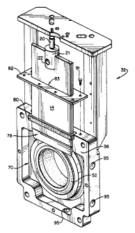
Fig. 2 is an internal perspective view of a housing member
used in association with the embodiment of the gate valve assembly
of Fig. 1, shown with the gate in the open position.
Fig. 3 is a perspective cross-sectional view showing another
embodiment of a gate valve assembly of the present invention.
- 2 -
CA 02240308 1998-06-11
Fig. 4 is an internal exploded perspective view of a housing
member used in association with the embodiment of the gate valve
assembly of Fig. 3, shown without the gate or primary sealing
sleeve installed.
Fig. 5 is a top plan view of a secondary~sealing member in
accordance with the present invention.
Fig. 6 is a front elevation in partial cross-section of the
secondary sealing member of Fig. 5.
Fig. 7 is a cross-sectional view of the secondary sealing
member taken along line 7-7 of Fig. 6.
DESCRIPTIONOF THE PREFERRED EMBODIMENTS
In the illustrated embodiment of the invention as shown in
Figs. 1 and 2, there is provided a va~,ve assembly 10 which includes
a housing 11 adapted to be inserted coaxially
into a pipeline.
The movable valve element is in the form of a flat, smooth,
imperforate gate plate 14 of uniform thickness mounted for
reciprocal movement in and out of the fluid flow-path through the
housing 11. The gate 14 is shown in the open position in Figs. 1
and 2. The reciprocal movement of the gate is controlled by a gate
actuator mounted on the upper end of the housing 11. The actuator
may, for example, be in the form of a piston and cylinder
arrangement; with piston rod 20 being provided at the lower end
with a bifurcated fitting 21 having holes 22 for insertion of a pin
to pivotally mount the piston rod 20 on the upper end of the gate
14. The actuator may also be a handwheel or an electric motor
drive. Further description of the actuator and its function are
- 3 -
CA 02240308 2001-06-13
,
not necessary to an understanding of the invention which relates
essentially to the valve structure within the housing and its
cooperation with the gate 14.
Housing 11 includes opposed similar halves 30 and 32 having
respective housing plates 34 and 36 which include outer generally
circular radial flanges 38 anc~ 40 and inner rectangular radial
flanges 42 and 44. A separate outer flange member 46, 48 is
secured to the outer face of each housing plate 34, 36 by means
such as screws 49. Additional bolt holes 45 are shown for use in
securing the pipeline companion flanges to the valve. Such a
bolt construction contributes to an increase in the operating
pressure rating for the valve. The housing halves are rigidly
secured together as by a series of bolts 26 extending through the
adjacent housing plates. The housing and general operational
features are similar to the valve of the above mentioned U.S.
Patent No. 4,895,181 and to which reference is made for further
detail. The housing plates 34 and 36 provide a narrow space of
sufficient width to pass gate 14 during operation of the valve.
This gate passage or chamber space is indicated at 50 in Fig. 1
and is of a fixed width slightly greater than the width of gate
14 when the bolt assemblies 26 are drawn tight except in the
central internal region where it opens outwardly to create an
enlarged space for clean out purposes, as described hereinafter
in greater detail. The housing halves are preferable ductile
iron or alloy castings for improved machinability and corrosion
resistance.
Primary sealing sleeve units S1 and 52 are mounted in the
respective housing halves. Each sleeve unit comprises an annular
- 4 -
CA 02240308 2001-06-13
resilient body 53, 54 of an elastomeric material such as natural
rubber or other suitable synthetic elastomer. Each of the sleeves
51, 52 is reinforced at its inner end by an annular shaped
stiffener ring 62, 63 which may be formed of a durable material
such as steel, hard polyurethane or equivalent plastic. The outer
flange members 46 and 48 seal against the axially outer ends of the
respective sleeves 51 and 52. .
The general configuration, features and functions of the
primary sealing sleeves 51, 52 and the stiffener rings 62, 63 in
the embodiment shown in Figs. 1 and 2 are similar to those of the
knife gate valve described in the above mentioned U.S. Pat. No.
4,895,181 to which reference is made for further detail.
In.,Figs. 3 and 4 there is shown an alternative embodiment of
the invention, with valve assembly 12 including a housing 15.
adapted to be inserted coaxially into~a pipeline. Gate 17 is
mounted for reciprocal movement by an actuator in and out of the
flow path through the housing 15.
Housing 15 includes opposed similar halves 31 and 33 having
respective housing plates 35 and 37. The housing halves are
rigidly secured together as by a series of bolts~27 extending
through the adjacent housing plates. Bolt holes 16 are provided
for use in securing the valve in the pipeline. The housing and
general operational features are similar to the valve of the above
mentioned ~.5. Patent No. 5,271,426 and to which reference is
made for further detail. The housing plates 35, 37 provide a
narrow space of sufficient width to pass gate 17 during operation
of the valve. This gate passage or chamber space is indicated at
47 in Fig. 3 and is of a fixed width slightly greater than the
width of gate 17 when the bolt assemblies
- 5 -
-,'. ',' ~ CA 02240308 1998-06-11
27 are drawn tight except at the upper and lower ends where it
opens outwardly to create an enlarged space for clean out purposes,
as described hereinafter in greater detail.
Primary sealing sleeve units 71 and 73 of this embodiment are
mounted in respective housing halves. Each sleeve unit comprises
an annual resilient body 75, 77 of an elastomeric material such as
natural rubber or other suitable synthetic elastomer such as
polyurethane. Each of the sleeves 71, 73 is reinforced at its
inner end by an annular shaped stiffener ring 79, 81 which may be
formed of a durable material such as steel, hard polyurethane or
equivalent plastic. Each sleeve unit 71, 73 has a'plurality of
compression holes 56 extending axially and arranged at intervals
relative to the circumference of the sleeve. These compression
holes 56 provide space for the displaced volume of sleeve
elastomeric material to flow into during opening and closing of the
gate 17. A groove 58 is provided along the inside surface of each
sleeve 71, 73 in an arc of approximately 120 degrees extending
approximately between the four o'clock and eight o'clock positions.
These grooves 58.assist in improving performance during the
closing cycle.
The general configuration, features and functions of the
primary sealing sleeves 71, 73 and the stiffener rings 79, 81 in
the embodiment shown in Figs. 3 and 4 are similar to those of the
knife gate valve described in the above mentioned U.S. Patent No.
5,271,426 to which reference is made for further detail.
As shown in Figs. 1 and 2, a secondary resilient seal member
80 is positioned above the primary sleeve units in a secondary
sealing slot 85 defined by the mating housing halves. The secondary
seal member 80 is a unitary, self-adjusting, deformable body of
- 6 -
',: ,'; ~ CA 02240308 1998-06-11
molded elastomeric material which is uniformly resilient throughout
its volume, such as natural rubber or other suitable synthetic
elastomer such as polyurethane. Since the secondary seal 80 is a
molded elastomer part, the seal construction is different from the
braided packing which is normally used to prevent leakage around a
knifegate. Thus the present construction is still considered to be
packingless.
As shown in Figs. 5 through 7, the secondary seal 80 has a
generally rectangular cross-section and an interior passage 84 to
allow for the passage of the gate member. The inner peripheral
edge 86 of the secondary seal 80 lines the interior passage 84 and
may be provided with ribs or lips 90 and grooves 92. The ribs 90
sealingly engage the entire circumference of the gate. The grooves
92 are capable of retaining a lubricating fluid such as grease,
oil, or the like to promote cohesive $,lid?ng of the gate during
operation. When the lubricating fluid is employed in the grooves
92, the groove and rib configuration allows a small amount of
lubricant to be released each time the gate passes through the seal
80. Gate lubrication is advantageously employed to provide
smoother gate action and longer seal life as wel~l:as to reduce the
amount of force necessary to actuate the gate. The secondary seal
unit 80 engages the gate 14 during the opening and closing cycles
and prevents any slurry which may be discharged between the primary
sleeves 51, 52 from leaking to the atmosphere around the gate or on
the actuator end of the valve. The secondary seal 80 also prevents
any outside contaminants from penetrating inside the primary
sleeves 51, 52.
The secondary seal 80 is secured within the housing by a
secondary seal retainer plate 82. This plate 82 is shown in Fig. 2
CA 02240308 1998-06-11
as having been lifted up from the seal 80, in order to show the
seal 80 more clearly. The secondary seal retainer plate 82 is
secured directly to the housing using bolts 91 or the like and has
a throughpassage 83 which aligns with the secondary seal interior
passage 84 and the gate chamber to allow full sliding movement of
the gate 14. While the primary sleeves 51, 52 prevent direct
slurry line pressure on the secondary seal 80, the secondary seal
80 is itself capable of withstanding full slurry line pressure in
the event of primary sleeve failure. Since the secondary seal 80
is thus dynamically self-adjusting, there is no need for constant
manual adjustment such as in the case of conventional packing in
order to stop leakage from the valve.
The embodiment of Figs. 3 and 4 also includes a secondary seal
88 of a construction similar to seal 80. The secondary seal 88 is
positioned in slot 64 and secured by retainer plate 65 with the use
of bolts 93. The throughpassage 66 of plate 65 aligns with seal
interior passage 89. The secondary seal 88 of this embodiment
functions in a similar manner to the seal 80 in the embodiment of
Figs. 1 and 2.
In the embodiment of Figs. 1 and 2, the lower edge of the gate
plate 14 is tapered on both sides to provide a relatively sharp
straight knife edge as shown at 78, and initially may extend within
clean out area 70, as shown in Fig. 1, but not far enough to
appreciably forcibly engage primary sleeve end portions 74 and 76.
This is the normal valve open condition of the valve assembly
operably mounted in a pipeline, wherein the gate has not yet
effectively penetrated the primary sleeve seal. In this position,
however, the gate has fully penetrated the secondary seal 80.
Thus, the secondary seal inner peripheral edge 86 is in continual
_ g _
CA 02240308 1998-06-11
contact with both sides of the gate during the opening and closing
cycles.
As shown in Figs. 1 and 2, the valve housing members 30, 32
are cast so as to provide an enlarged clean out area 70 when mated.
The clean out area 70 extends around the entire circumference of
the primary sleeve units 51, 52 as shown in Fig. 2.so as to provide
containment for any slurry discharge which may escape the primary
seal during the opening and closing of the valve. The housing is
further provided with one or more flush ports 95 which are in fluid
communication with the clean out area 70 to facilitate controlled
draining or flushing of the contained slurry.
The gate operating cycle begins in the open position, which is
shown in Figs. 1 and 2. In the closing cycle, the descending gate
14 lower edge enters and forces apart the upper sector of the
primary sleeves 51, 52 as it is sli'da~ly disposed between primary
sleeve end faces and then forces apart the end portions 74 and 76.
The valve moves from an open to a closed position as the gate
14 separates the two primary sleeves 51, 52 that seal against each
other when the valve is open. Since the sleeves 51 and 52 are made
of a resilient elastomer which is a noncompressible solid, the
sleeves 51, 52 must flow out of the way as the gate 14 slides
between them, separating the sleeves a distance equal to the
thickness of the gate 14. As the gate 14 penetrates further toward
the closed position, the seal between sleeve end portions 74 and 76
is progressively parted while the relatively soft sleeve material
effectively flows around the knife edge 78. As the gate separates
the primary sleeves 51, 52, it blocks the flowing slurry in the
pipeline providing tight closure of the valve once'the gate has
reached its full travel across the port of the valve.
- 9 -
CA 02240308 1998-06-11
In the final closed valve position, the knife edge 78 has
passed the lower sector of the primary sleeves 51, 52 and the gate
is disposed between them, while the knife edge projects into the
space below. At this time the opposed flat smooth side surfaces of
the gate plate 14 are uniformly engaged under compression by the
compressed primary sleeve inner end portions 74, 76, which may even
be substantially flattened, so that there is a complete annular
seal of good radial extent within the valve. At this time the
primary sleeve inner end portions 74, 76 are in uniform maximum
compression and the internal pressure of the fluid or slurry in the
pipeline will further force the upstream primary sleeve inner end
into engagement with the gate 14, aided by the inner surface
portion of the primary sleeve. The combination of the knife edge
and the gate and the soft deformable material of the sleeve inner
end portions minimize leakage from 'the valve during gate-closing
and opening operations.
In the gate closed condition, the area of the gate 14 that is
unsupported is minimized by the present invention so that a maximum
pressure rating for the valve can be obtained. During movement of
the gate 14 from the closed position to the open position,
substantially the reverse of the above described procedure takes
place, the resiliency of the seal material maintaining sealing
sliding contact between the sleeve inner end portions 74, 76 and
the gate 14 until the gate 14 is withdrawn from between the
sleeves.
Any slurry which may seep through between the primary sleeves
51, 52 during the gate opening or closing cycles is collected in
the clean out area chamber 70 for eventual flushing through the
flush port or ports 95. The flush ports 95 may be located at
- 10 -
,' , ~ CA 02240308 1998-06-11
intervals along the bottom and side walls of the housing as shown
in Fig. 2 and allow for pipe or hose connection for controlled
draining or flushing of the contained slurry. No slurry discharge
escapes to the atmosphere outside of the valve and the secondary
seal 80 prevents slurry discharge from reaching the actuator end of
the valve. In this regard, a most important advantage of the gate
valve construction of the present invention is that there is no
leakage to the outside when the valve is fully open and no leakage
to the outside or past the gate internally when the valve is fully
closed. Additionally, the presence of the enlarged clean out area
70 and the secondary seal 80 allows the valve operating pressure
rating to be increased.
The valves of the invention are bi-directional or two-way
valves; that is, they may control flow in either direction in the
pipeline and may be reversed end for end. The primary sleeve units
51, 52 of Figs. 1 and 2 are essentially identical so that either
may be replaced one for the other and function as described above
in the assembly. Sleeve units 71, 73 of Figs. 3 and 4 are also
essentially identical so that either may be replaced one for the
other. The individual sleeve units are readily removed and replaced
when damaged or worn, without having to disassemble the housing
assembly.
In the embodiment as shown in Figs. 3 and 4, there is provided
an alternative construction for the clean out area of the gate
valve of the present invention. In this embodiment, the upper
indented clean out area 94 extends from the slot 64 for the
secondary seal 88 at the upper end of the valve to the
throughpassage 96 of the housing. A horizontal slot 97 in the wall
of the housing is in fluid communication with the clean out area
- 11 -
CA 02240308 1998-06-11
94. The slot 97 is provided with flush out ports 99 at each end
thereof. A lower clean out area 98 is located below the
throughpassage 96, with area 98 extending to the bottom of the
housing as shown in Fig. 4. The lower clean out area 98 is in
fluid communication with the upper clean out area 94.
As shown in Figs. 3 and 4, a drain plate 100 and a drain plate
gasket 102 are secured to the bottom of the housing 11 by bolts 101
so as to form the lower boundary of the lower clean out area 98.
Aligned flush ports 104 provided within the drain plate gasket 102
and drain plate 100 allow for pipe or hose connection for
controlled draining or flushing of the contained slurry in clean
out area 98. The presence of the enlarged clean out area allows
the valve to be constructed with a reduced body weight for easier
handling while maintaining optimum strength and durability.
The general operation of the gate valve of Figs. 3 and 4 is as
described in U.S. Patent No. 5,271,426 to which reference is made
for further detail.
The invention may be embodied in other specific forms without
departing from the spirit or essential characteristics thereof.
The present embodiments are therefore to be considered in all
respects as illustrative and not restrictive, the scope of the
invention being indicated by the appended claims rather than by the
foregoing description and all changes which come within the meaning
and range of equivalency of the claims are therefore intended to be
embraced therein.
What is claimed and desired to be secured by Letters Patent
is:
- 12 -