Note: Descriptions are shown in the official language in which they were submitted.
CA 02240414 1998-06-15
WO 97/22168 PCT/US96/20025
~$OLATED ELECTRICAL POWER BUPPL~C
FIELD OF INDENTION
The present invention relates to isolating and
suppressing transient electrical pulses and high frequency
interference in power systems. More specifically, the
present invention is directed to a ground noise suppressor
which attenuates undesirable transient voltage pulses, fault
currents and high frequency interference with an inductor
placed after the secondary winding of an isolation
transformer.
DACRGROUND OF INVENTION
In many electrical applications, uninterrupted
power free from transient currents, voltages, and other
forms of electrical noise are required. Those undesirable
pulses and noise may be generated by outside disturbances
such as lightning, motor generators, electrically driven
devices etc., which originate within a facility from other
loads interacting with each other or interconnected via the
electrical distribution or data cables. There is thus a
need for suppression of unwanted electrical noise and
isolating transient pulses from any external power source.
Additionally, there are fault voltages which may be
generated within an electrical device. For example, in
1
CA 02240414 1998-06-15
WO 97/22168 PCT/US96/20025
computer systems, a large majority of data loss or system
problems result from poor grounding of power supplies.
These problems are compounded with increased gate densities
on integrated circuits.
Electrical contamination of only half a volt may
cause data errors in present computer systems. With digital
logic referencing ground at all times, it is imperative that
a zero reference free of transient voltages or currents or
noise be provided on the ground plane. Electrical impulses
of greater magnitude are even more damaging because they may
degrade a computer system's performance by eating away at
the silicon underlying integrated circuits causing pitting
on the surface. This in turn eventually degrades or
destroys integrated circuit operation leading to complete
25 data and system loss.
A typical grounding system has multiple functions
which include personnel safety, serving as a steady zero
electronic~volt reference, lightning protection and a path
for fault current. There are several established standards
2o for proper grounding and proper alternating current (AC)
distribution. Those include~UL, ANSI C62.41, and IEEE 587
standards and National Electrical Codes, all of which must
be met for normal applications. Additionally per UL, power
isolators must have a practical limit to withstand at least
2
CA 02240414 1998-06-15
WO 97/22168 PCT/US96I20025
6000 volts to compensate for conductor spacing of typical
electrical wiring systems. Traditionally, surge suppressors
have been used to nullify (limit) transient voltages.
Unfortunately such devices convert surge voltages to
undesirable surge currents on the system data ground.
One method of eliminating unwanted transient
voltages uses an isolated power supply. Typically this is
accomplished by an isolation transformer. The transformer's
primary windings are connected to an external alternating
current (AC) voltage source. The electrical load sought to
be protected is connected to the secondary windings and thus
is electrically isolated from the AC voltage source and any
transients from the external source. Although this
arrangement eliminates some transients other current and
voltage surges such as ground fault current may still occur
in the secondary winding and thus be passed to the load.
Additionally, as the primary and secondary grounds are
electrically tied to the same "ground plane," there is no
way to stop unwanted noise from choosing any path it wishes
to the '~protected" load on the secondary winding or to the
primary winding.
~ Another method of shunting transient pulses
involves tying an impedance to the primary ground input of a
transformer. In this configuration both the primary and
3
CA 02240414 1998-06-15
WO 97/221b8 PCT/US96/20025
secondary windings of the transformer have a source (line
power), neutral and ground tap. The secondary ground tap is '
connected to the primary ground tap and is tied to an
external ground through the impedance. The impedance thus
shunts transient high frequency current away from the input
voltage lines of the electrical load connected to the
secondary windings but allows 60 Hz AC voltage to pass
through the transformer windings. The impedance is
typically a toroid having a number of windings around a
cylindrical core.
The toroid°s maximum impedance is limited due to
the diameter of the core. Additionally, the wire thickness
necessary for high frequency applications limits the number
of turns on the toroid. Coupling the toroid on the
transformer°s primary windings leaves a potential difference
between the earth ground, chassis ground, isolated ground
and the neutral ground of the load. Thus, because of the
toroid's size, UL regulations limit the isolating power
source using this method to 5 amps. Additionally, UL
regulations require double insulation, such as a layer of
heat shrink, air space andJor electrical insulating paper,
on all the wires of the isolator device, isolator
components, and the load itself for safety reasons. Such
requirements for isolator devices are understandably
4
CA 02240414 2005-10-12
difficult to meet and limit performance. In addition,
external ground wires must be tied to the earth ground or
isolated ground if not double insulated. Thus, isolated
grounds with this type of devices still presents a
challenge to maintaining the zero reference for high
current, high voltage loads.
Accordingly there is a need for an isolated
power supply that provides a true ground free from a wide
range of transient voltages, currents and high frequency
interference. There is also a need for a power isolator
which meets safety standards for larger power sources over
5 amps. Additionally, there is a need for a power isolator
which does not require double insulation on all electrical
surfaces or connected loads.
SUMMARY OF THE INVENTION
The above needs are met by an isolated power
supply in accordance with the present invention for
suppressing fault currents and noise from an external
three-wire alternating current power source having an
earth ground. The present invention isolates the
alternating current power source and ground which
powers the electrical load and provides a signal
reference ground. The isolated power supply has an
isolation transformer with a primary and
5
CA 02240414 1998-06-15
WO 97/221b8 PCTlUS9b120025
a secondary winding. Each of the windings has respective
source, neutral, and shield leads. The primary and '
secondary windings are magnetically coupled but are isolated
from direct electrical connection to each other.
The primary leads are electrically coupled to the
alternating current power source. The secondary leads are
electrically coupled to the electrical load. Thus the
isolation transformer magnetically isolates the electrical
load from the alternating current power source. The
secondary shield lead and the primary shield lead are
electrically coupled together as an earth ground. An
inductor is electrically coupled between the secondary
neutral lead and the earth ground providing electrical
isolation between the earth ground and the secondary neutral
lead.
Numerous other aspects and advantages of the
present invention will become apparent from the following
drawings and detailed description of the invention and its
preferred embodiments.
BRIEF' DESCRIBTION OF THE DRAWINGS
The present invention may be better understood
with reference to the detailed description in conjunction
6
CA 02240414 1998-06-15
WO 97/22168 PCTlU596/20025
with the following figures where like numerals denote
identical elements, and in which:
FIG. 1 is a perspective view of the power isolator
of the present invention;
FIG. 2 is a front view of the isolation ground
circuit board of the present invention;
FIG. 3 is a perspective view of the isolation
ground circuit board of the present invention;
FIG. 4 is a cutaway view of one of the transformer
designs of the present invention;
FIG. 5 is a circuit diagram of the isolation
circuit of the present invention; and
FIG. 6 is a perspective view of a ground isolation
circuit board of a second embodiment of the present
invention.
DETATLED DESCRIPTION OF THE PREFERRED EMBODIMENT
Figure 1 is a perspective view of a power isolator
10, according to the present invention. The power isolator
10 provides electrical isolation for an electrical load 12,
from an external AC power source 14. The external AC power
source has a source lead, a neutral lead, and an earth
ground lead. The isolator 10 provides a primary earth
ground potential while electrically isolating the load 12.
7
CA 02240414 1998-06-15
WO 97/22168 PCT/US96/20025
In the preferred embodiment, the isolator 10 is capable of
isolating an alternating current power source of 8.3 amps at
120 volts. Of course, other voltage and current levels may
be isolated using the present invention. For example, the
present invention may be modified for operation with power
sources having a current in the range of .5-225 amps at 120
volts. Additionally, other voltages at different phases may
also be isolated using the present invention.
The isolator 10 has a metal cover 16 which is
30 normally installed on a metal chassis 18 for protecting the
internal components. Screws (not shown) or other fastening
devices are used to attach the cover 16 to the chassis 18.
The chassis 18 has a bottom plate 20, and a pair of
sidewalls 22 and 24. An isolation transformer 30 is mounted
on the bottom plate 20. As will be explained below, the
isolation transformer 30 prevents direct voltage flaw to the
electrical load 12 connected to the isolator 10, thus
isolating the alternating current (AC) power source 14. The
electrical load 12 may be any electrical device such as a
2o computer, electrically sensitive appliance or data storage
device which requires an isolated ground protected from
transient currents and voltages for proper operation. -
The external alternating current source 14 is
typically connected to the isolator 10 by a power cord 32.
r
8
CA 02240414 1998-06-15
WO 97/22168 PCT/US96/20025
The power cord 32 may be connected to the alternating
current source 14 by a three pronged plug 34.
Alternatively, the power cord 32 and the plug 34 may be
replaced with a hard wire connector. The power cord 32 has
a source line 36, a neutral line 38, and a ground line 40.
An input/earth ground stud 26 is coupled to the chassis 18
on the sidewall 24. The stud 26 serves as an external
connector to reference earth ground. An isolated binding
post 28 is also attached to the sidewall 24. The isolated
binding post 28 is tied to the conditioned ground as will be
explained below.
A circuit breaker/fuse switch 42 is mounted on the
sidewall 22. The circuit breaker/fuse switch 42 allows a
user to turn on and off the isolator 10 by interrupting the
electrical flow on the source line 36. Additionally, the
circuit breaker/fuse switch 42 will interrupt the source
line 36 thus cutting off power to the electrical load 12 on
detecting an abnormal fault current. The source line 36 and
the neutral line 38 are twisted together and wrapped by a
ferrite bead 44 before being connected to the transformer
30.
An isolation power circuit board 46 is mounted in
the chassis 18 and is physically separated from the
isolation transformer 30. The isolation power circuit board
9
CA 02240414 1998-06-15
WO 97/22168 PCT/US96/20025
46 has a component surface 48 which faces the isolation
transformer 30. The isolation power circuit board 46 also
has a connector surface 50 which faces the sidewall 24. Two
isolated ground connector/terminal boxes 52 and 54 are
mounted between the connector surface 50 of the isolation
ground board 46 and the sidewall 24. The isolated ground
connector boxes 52 and 54 are offset from the surface of the
isolation circuit board 46 to prevent an antenna effect such
as EMF or RF waves from the transformer 30. The isolated
ground connector boxes 52 and 54 also support the isolation
circuit board 46 on the sidewall 24. As will be explained,
the connector boxes 52 and 54 are electrically isolated from
the external current source 14.
Each of the connector boxes 52 and 54 have a
socket plate 56 which is flush against the sidewall 24. The
socket plate 56 has two standard three hole sockets 58 which
serve as power connection sources for electrical devices
such as the electrical load i2. In the preferred
embodiment, the socket plates 56 are colored orange
indicating an isolated ground power supply. Each of the
sockets 58 of the outlets 52 and 54 have a source socket, a
neutral socket and a ground socket which are a straight
blade type socket. Different sockets such as a twist lock
CA 02240414 1998-06-15
WO 97/22168 PCT/US96/20025
or terminal strips may be used instead of the straight blade
type for higher current isolation devices.
The transformer 30 has a primary source lead 60, a
primary neutral lead 62 and a primary electrostatic shield
lead 64. The primary source lead 60 is connected to the
source line 36 while the primary neutral lead 62 is
connected to the neutral line 38. The transformer 30 also
has a secondary source lead 66, a secondary neutral lead 68,
and a secondary electrostatic shield lead 70. A source line
72 connects the secondary source lead 66 to a source tab 76
mounted on the isolation ground board 46. A neutral line 74
connects the secondary neutral lead 68 to a neutral tab 78
mounted on the isolation ground board 46. The source line
72 and the neutral line 74 are twisted together and wrapped
by a ferrite bead 80.
The isolation ground board 46 is connected to orie
end of an insulated ground wire 82. The other end of the
ground wire 82 and one end of the ground line 40 are
connected to a copper strip 84 which is in electrical
contact with the bottom plate 20 of the chassis 18. The
primary electrostatic shield lead 64 as well as the
~ secondary electrostatic shield lead 70 are also connected to
the copper strip 84. The copper strip 84 is a relatively
wide band for better high frequency voltage flow. The
11
CA 02240414 1998-06-15
WO 97/22168 PCT/US96/20025
copper strip 84 in conjunction with the chassis 18 serves as
an earth ground. A light emitting diode (LED) 86 is mounted
on the sidewall 24. The LED 86 indicates whether power is
flowing to the connector boxes 52 and 54.
Figure 2 shows a front view of the component
surface 48 of the isolation ground circuit board 46. Figure
3 shows a perspective view of the connector surface 50 of
ground circuit board 46. With reference to Figures 2 and 3,
the source line 72 is connected to the source tab 76, while
the neutral line 74 is connected to the neutral tab ?8. The
source tab 76 is electrically connected to a source plate 88
which is in turn electrically connected to the source
sockets of the sockets 58 of the connector boxes 52 and 54.
The neutral tab 78 is electrically connected a neutral plate
90 which is in turn electrically connected to the neutral
sockets of the sockets 58 of the connector boxes 52 and 54.
The LED 86 is connected to the source line 72 through a
dropping resistor. The insulated ground wire 82 is
connected to a ground plate 92.
A ferrite bead 94 surrounds a wire connecter which
electrically connects the neutral plate 90 to a ground strip
96. One lead of a filter resistor 98, which is preferably 5
watts in the preferred embodiment, is coupled to a
connection pad 100. The other lead of the filter resistor
12
CA 02240414 1998-06-15
WO 97/22168 PCT/US96/20025
98 is electrically coupled to the neutral plate 90. One
lead of a fault resistor 102, which is preferably 5 watts in
the preferred embodiment, is electrically connected to the
ground plate 92. The other lead of the fault resistor 102
is electrically connected to the neutral plate 90.
Two capacitors 104 and 106 are also mounted on the
isolation ground board 46 for filtering high frequency
pulses. One lead of each of the capacitors 104 and 106 is
electrically coupled to the source plate 88. The other lead
IO of the capacitor 104 is electrically coupled to the resistor
98 via the contact plate 100. The other lead of the
capacitor 106 is electrically coupled to the neutral plate
90. A metal oxide varistor (MOV) 108 is mounted on the
isolation ground board 46 for high voltage clamping. One
lead of the MOV 108 is coupled to the source plate 88 while
the other lead is coupled to the neutral plate 90. One lead
of an inductor such as a toroid 110 is electrically coupled
to the secondary neutral lead 68 of the isolation
transformer 30 via the neutral plate 90. The other lead of
the toroid 110 is electrically coupled to the ground plate
92.
~ The toroid 110 has a cylindrical core which is
typically 1-6 inches in diameter. The diameter of the
toroid 110 depends on the magnitude of the source current to
13
CA 02240414 1998-06-15
WO 97/22168 PCTlUS96/20025
be isolated. The toroid core is a magnetic material such as
iron and ferrite which is overwrapped with epoxy. A number
of copper Wire turns are wound around the core. In the
preferred embodiment the wire size and number of windings is
determined by the National Electrical Code Requirement.for
fault current flow for varying ampacities at 60 Hz. Of
course other windings, wire sizes, and core sizes may be
used with the present invention.
The above described components mounted on the
isolation circuit board 46 serve the function of attenuating
transient high voltages and shunting fault current over a
wide range of frequencies. In the preferred embodiment, the
leads of the electrical components on the isolation circuit
board 46 have mating holes in their respective plates. The
leads are placed in the mating holes and soldered in place
to insure maximum electrical contact and to minimize the
risk of spark jump.
The plates 88-92, strip 96, and pad 100 in the
preferred embodiment are made of single sided FR-4 2.0 oz.
tinned copper. The plates 88-92, strip 96, and pad loo are
all embedded within the circuit board 46 to minimize risk of
electrical shocks. The only exposed metal contacts are
connected to the electrical components. The plates 88-92,
strip 96, and pad 100 have a relatively large surface area
14
CA 02240414 1998-06-15
WO 97/22168 PCT/US96/20025
for high frequency, high current flow displacement. Spacing
is maintained between the plates 88-92, strip 96, and pad
100 to comply with UL safety requirements to prevent voltage
arcing between them.
Figure 4 is a cutaway view of the isolation
transformer 30. The transformer is centered around a ferro-
magnetic core 120. The core i20 is surrounded by a primary
winding 122 and a secondary winding 124. In the preferred
embodiment, the windings of the primary winding 122 and the
to secondary winding 124 are in a 1:1 ratio. Of course, other
winding ratios may be used in conjunction with the present
invention. Additionally, other transformer types such as
ferroseonant transformers may also use the present
invention.
The secondary winding 124 separated from the core
12o by a tube 128. Each of the secondary winding layers are
separated from each other by a secondary layer insulation
sheet 130. In the preferred embodiment this sheet is made
of Nomex but any other electrically insulating material may
be used. The secondary winding 124 is also separated from
the remainder of the transformer 30 via a secondary wrap
' insulation 132, which is also preferably constructed of
r
Nomex. A secondary shield 134 serves to insulate the
secondary winding 124 from high frequency noise. The
CA 02240414 1998-06-15
WO 97/22168 PCT/CTS96/20025
secondary shield 134 is made of copper in the preferred
embodiment. A primary/secondary shield insulator 136 serves '
to separate the secondary shield 134 from other electrical
windings. The insulator 136 is preferably made of Nomex in
the present invention. A copper primary shield 138 borders
the secondary shield 134 and is separated by a primary
insulation layer 140 which is also made of Nomex.
Both the primary shield 138 and the secondary
shield 134 are connected to the copper strip 84 via the
primary and secondary electrostatic shield leads 64 and 70
which in combination with the chassis 18 serves as an earth
ground. Each of the primary windings 122 are separated by a
primary layer insulation sheet 142 which is also preferably
made of Nomex. The entire primary winding 122 is surrounded
by a Nomex primary wrap 144. The transformer has a lead tab
146 which is insulated on the outside of the transformer 30
by an insulation layer 148. Finally, the entire transformer
30 is wrapped with a glass tape layer 150.
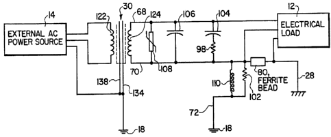
Figure 5 is a circuit diagram incorporating the
elements showing the isolation circuit board 46. The
isolation transformer 30 is double shielded and has low
impedance which isolates noise from the electrical load 12
which is connected via the connector box 52 to the secondary
leads of the secondary winding 124. The isolation
Zs
CA 02240414 1998-06-15
WO 97/22168 PCTICTS96/20025
transformer 30 serves to isolate noise by providing a low
' impedance path for fault current flow. As described above,
the primary shield 138 and the secondary shield 134 are
connected to the chassis 18 via the copper strip 84 which
serves as a primary earth ground.
The electrical source from the leads 66, 68, and
70 of the secondary winding 124 of the isolation transformer
30 are further filtered with the components mounted on the
component surface 48 of the ground isolation board 46.
These components are separated from the isolation
transformer 30 for greater isolation from transient
electrical pulses.
The metal oxide varistor (MOV) 108 is tied between
the secondary source lead 66 and the secondary neutral lead
68 of the isolation transformer 30. The MOV 108 serves to
clamp any high voltage which could couple through the
transformer 30 to the electrical load 12. Similarly, the
capacitor 106 is tied between the secondary source lead 66
and the neutral lead 68 of the isolation transformer 30.
The capacitor 106 is designed to attenuate pulses in the 100
kHz range which clamps ANSI/IEEE pulses. The resistor 98 is
placed in series with the capacitor 104 to attenuate any
ringing sine waves or voltage waves which are coupled
17
CA 02240414 1998-06-15
WO 97/22168 PCT/US96/20025
through the isolation transformer 30 from an ANSI/IEEE
pulse. '
The resistor 102 is wired in parallel with the
toroid 110 and connected to the ferrite bead 80. The
ferrite bead 80, resistor 102 and toroid 110 are a ground
filter circuit. Fault currents generated from the load 12
are attenuated through the transformer 30 and the earth
ground (the chassis 18). The ground filter circuit
attenuates high frequency voltage and current. Fault
current passes back straight through the primary winding 122
of the isolation transformer 3o and also to the earth ground
since the impedances on both are similar. The diversion of
the fault current protects the neutral lead 68 connected to
electrical load 12. The ferrite bead 80 is designed to
filter current in the 70-200 kHz range. Thus, current in
this range is filtered before it reaches the transformer 30.
The toroid 110 causes the secondary electrostatic
shield lead 70 at the output of the filtering circuit to be
isolated such that only the electrical load coupled to the
connector box 54 will be conditioned. Thus, no double
insulation is necessary for the toroid 220 and the resistor
102. The chassis 18 provides a wide conductor for
attenuating high frequency current. Low frequency current
such as that under 1 kHz is passed through by the toroid
I8
CA 02240414 1998-06-15
WO 97/22168
PCT/Y1S96120025
110. All of the components tied to secondary leads of the
transformer 30 provide less than .5 ohm resistance at low
frequencies of less than 1 KHz such as 60 Hz household
current. Thus, low frequency current and voltage are
permitted to pass. At these low frequencies, there is no
voltage potential between the secondary neutral load 68 and
the secondary electrostatic shield lead 70 as both are tied
to the earth ground. Thus, the electrical ground of the
load 12 is at the same voltage as the earth ground.
to However, the secondary neutral lead 68 is a conditioned
ground which is isolated. External connections such as an
isolated/insulated binding post 28 from the chassis 18 may
then be coupled to the electrical~ground for a conditioned
ground.
15 The invention may be adapted to different current
and voltage requirements by increasing or decreasing the
shielding and plate areas on the isolation circuit board 46.
Additionally, other connector boxes for further electrical
loads may be added. Figure 6 shows a second embodiment of
20 the present invention which adds a third connector box.
Identical elements to those of the isolator power circuit
board 46 in Figure 2 have identical figure numbers. The
toroid 110 is proportionally larger than its counterparts in
the previous embodiment to provide the proper shielding and
19
- CA 02240414 1998-06-15
WO 9'7/22168
PCT/(JS96/20025
isolation for the addition of a third connector box 160. As
with the other two connector boxes 52 and 54, the connector
box 160 is mounted above the circuit board 46 to maximize
shielding and reduce risk of stray voltage jumps.
A ground wire 162 is connected to the ground
socket of connector 160. The ground wire 162 is connected
to the ground socket of connector box 52 which is in turn
electrically coupled to the ground plate 92. A source wire
164 couples the source sockets of the connector box 160 and
the connector box 54. A neutral wire 166 couples the
neutral sockets of the connector box 160 and the connector
box 54. In such a manner all three connector boxes 52, 54
and 160 are coupled common taps to the secondary leads of
the isolation transformer 30.
The above described embodiments are merely
illustrative of the principles of this invention. Other
arrangements and advantages may be devised by those skilled
in the art without departing from the spirit and scope of
the invention. Accordingly, the invention should be deemed
not to be limited to the above detailed description but only
by the spirit and scope of the claims which follow.