Note: Descriptions are shown in the official language in which they were submitted.
CA 02240469 1999-02-O1
-1-
LIGHTWEIGHT HOSE WTTH
A HELICALLY-WOUND REINFORCING MEiI~ER
AND METHOD FOR MAHING THE SAME
BACKGROUND OF THE IIWFNTION
Field of the Invention
This invention relates to a lightweight hose, and more specifically, to a
hose constructed from a lightweight material and having a reinforcing material
formed
therein. In addition, the invention also relates to a method for forming a
hose
according to the invention.
Description of the Related Art
It is known to employ a hose to provide a conduit through which fluids
under various degrees of pressure can flow. Typically, the hose is connected
at one end
to a source of the fluid, and at an opposite end to a particular destination
to which the
fluid is to be delivered. In some vehicle applications, such as in vehicle
engines or
vehicle air conditioning systems in the aircraft industry, the weight of all
components,
including any hoses, is critical and must be minimized without sacrificing the
structural
integrity thereof.
Hoses for lightweight applications arc typically made of silicone,
urethane and/or polyether sulphone. It has been known to provide such hoses
with
more than one layer, or "ply," to increase the struc,~haal stability of the
hose. However,
these hoses typically require additional plies to be adhesively bonded to one
another or
wlcanized to ensure that the plies of the hose are securely mounted together.
The
manufacturing process is labor intensive and costly. Also, multiple plies of
the above
materials tend to add significant weight to hoses which, in turn, add weight
to the
system in which the hoses are installed.
It is known to manufacttm lightweight hoses on a mandrel of finite
length. A first pIy of material is wrapped amend the mandrel and then
additional plies
CA 02240469 1998-06-25
WO 97/24543 PCT/LTS97/00232
-2-
are added, usually with an adhesive between adjacent plies. The hose is then
typically
vulcanized to complete the process. Currently, hoses are typically of a
relatively short
finite length, limited by the longitudinal length of the mandrel. In addition,
these hoses
are relatively heavy and can require several plies of material and/or
relatively thick
plies of material to ensure their structural integrity.
SUMMARY OF THE INVENTION
The hose disclosed herein overcomes the limitations of the prior art in
the nature of its lightweight tubular wall having a helical reinforcing member
contained
therein. The hose can be made either by a process on a finite-length mandrel
or by a
continuous process wherein a substantially longer length of hose can be
manufactured.
Further, various embodiments of end cuffs and connectors for the hose
disclosed herein
are provided which include threads having a substantially equal pitch as the
helical
reinforcing member.
In one aspect of the invention, a lightweight conduit is characterized by
a tubular wall formed of at least one ply of heat seamable material and at
least one
helical member whereby the ply is bonded to itself and to the reinforcing
member
without additional adhesive.
The heat seamable material is preferably reinforced in the warp and fill
directions. In addition, the tubular wall is preferably formed of an inner ply
and an
outer ply whereby the helical member is disposed between the inner ply and the
outer
ply. In another aspect of the invention, a helical ridge is formed in the
tubular wail in
alternating pitch with the helical member. Additional helical members are
optionally
provided in the tubular wall whereby the additional helical members are
disposed in
alternating pitch with respect to the first helical member. The helical
members are
preferably formed of a corrosion-resistant and flame-retardant material such
as a resin-
impregnated fabric andlor a rigid polymer. The plies are typically overlapped
with the
helical member disposed within the overlapping portions.
In another aspect of the invention, the tubular wall forms a cuff adapted
to be mounted at a first end and a second end to first and second conduits.
The first end
~ 0 of the cuff is provided with an annular groove which receives a
conventional press-fit
connector. The second end of the cuff has an interior surface which is
provided with
threads adapted to receive a threaded connector. The second end of the cuff
also has an
CA 02240469 1998-06-25
WO 97124543 PCT/LJS97/00232
-3-
exterior surface which is provided with threads adapted to receive a threaded
connector.
In an additional aspect of the invention, the tubular wall forms a conduit
having at least three ports. Optionally, the tubular wall is formed into
connectors of
S various shapes including, but not limited to, a T-shaped or a Y-shaped
connector.
In a further aspect of the invention, a combination of a lightweight
conduit and a cuff and/or a connector is characterized by the conduit having a
tubular
wall with an outer surface and a first and a second end and the cuff having a
tubular
wall and a first and a second end. The outer surface of the conduit has a
helical
protrusion which defines a predetermined pitch and either the first or second
end has an
interior surface provided with threads defining a predetermined pitch
substantially
equal to the pitch of the helical protrusion on the conduit.
The invention also relates to a method for forming a lightweight,
conduit, including but not limited to, the described embodiments. The method
is
characterized by the steps of providing a mandrel, wrapping at least one ply
of heat
seamable material around the mandrel so that at least one portion overlaps
another
portion, wrapping an elongated member helically around the mandrel, heating
the
material and the member to a predetermined bonding temperature for a
predetermined
period of time wherein the overlapping portions will adhere to one another
forming a
conduit, and removing the conduit from the mandrel.
The method in one aspect includes the step of providing a helical groove
in the mandrel. Alternatively, the method is characterized by the step of
providing a
helical protrusion on the mandrel prior to the step of wrapping at least one
ply of a heat
seamable material around the mandrel. In yet another variation, one ply of
heat
seamable material is wrapped around the mandrel so that overlapping portions
of each
successive wrap of material are provided. Preferably, the elongated member is
within
the overlapping portions of the material, and wrapped helically between them.
Optionally, the method further comprises the step of wrapping a second
elongated
member helically around the mandrel. The elongated members are formed from
materials including, but not limited to, a resin-impregnated fabric or a rigid
polymer.
In another aspect of the invention, the method is automated by providing
a first feedable supply of the heat seamable material, providing a second
feedable
supply of the elongated member, providing a drive mechanism operably connected
with
CA 02240469 1998-06-25
WO 97124543 PCT/US97/00232
the first feedable supply and the second feedable supply, and operating the
drive
mechanism to supply the mandrel with heat seamable material from the first
feedable
supply and the elongated member from the second feedable supply. This method
further comprises the steps of providing a nozzle adjacent the mandrel, and
dispensing
4
heated fluid from the nozzle as the material is wrapped around the mandrel.
BRIEF DESCRIPTION OF THE I~~W1NGS
The invention will now be described with reference to the drawings in
which:
FIG. I is a perspective view of a first embodiment of a lightweight hose
according to the invention;
FIG. 2 is a cross-sectional view of the hose taken along lines 2-2 of
FIG. 1;
FIG. 3 is a perspective view of the hose of FIGS. 1-2 being formed on a
mandrel;
FIG. 4 is a fragmentary, longitudinal cross-sectional view of a second
embodiment of a lightweight hose according to the invention;
FIG. 5 is a diagrarnrnatical view showing a bending characteristic of the
hose of FIG. 4;
FIG. 6 is a perspective view of the hose of FIGS. 4-5 being formed on a
mandrel;
FIG. 7 is a cross-sectional view of an alternative embodiment of the
mandrel of FIG. 6;
FIG. 8 is a cross-sectional view of a third embodiment of a lightweight
hose according to the invention;
FIG. 9 is a cross-sectional view of a fourth embodiment of a lightweight
hose according to the invention;
FIG. 10 is an enlarged portion of FIG. 9 showing an overlapping region
of successive wraps of a material forming the hose of FIG. 9;
FIG. 11 is a cross-sectional view of a portion of the hose of FIGS. 9-10
on a side elevational view of a mandrel;
FIG. 12 is a side diagrammatical view of a continuous forming process
for the hose of FIGS. 9-10;
CA 02240469 1998-06-25
WO 97/24543 PCT/US97I00232
-5-
FIG. 13 is an end view of the process of FIG. 12;
FIG. I4 is a perspective view of a cuff for attachment to an end of any of
the embodiments of the hose according to the invention;
FIG. 15 is a cross-sectional view of the cuff of FIG. I4 and a
corresponding conventional conduit for attachment at one end;
FIG. I 6 is a fragmentary, cross-sectional view of the cuff of FIG. I4
showing the attachment of the cuff to a lightweight hose according to the
invention;
FIG. 17 is a longitudinal cross-sectional view of a mandrel for forming
the cuff of FIG. 14;
FIG. 18 is a perspective view of a T-shaped connector for two or more
hoses; and
FIG. 19 is a perspective view of a Y-shaped connector for two or more
hoses.
DETAILED DESCRIPTION OF THE PREFERRED EMBODIMENTS
Referring now to the drawings and to FIGS. 1-2 in particular, a length of
a first embodiment of a lightweight hose 10 is shown comprising a tubular wall
12
having at least an inner ply 14 and an outer ply 16. The tubular wall 12 is
reinforced by
a helical member 18. The helical member 18 maintains the integrity of a
transverse
cross-section of the tubular wall 12 by allowing gathering between adjacent
pitches of
the helical member I 8 during flexing of the hose 10. The helical member 18 is
preferably formed of a metallic or polymeric material, such as nylon or
stainless steel.
'The inner and outer plies 14 and I 6, respectively, are preferably formed
from a lightweight, homogeneous, heat-seamable, polyester film, reinforced in
the warp
and fill directions. ORCOFILM~ material, distributed by Orcon Corporation, l
570
Atlantic Street, Union City, California 94587, and in particular, ORCOFILM~ AN-
47R and AN-49R compositions have been found to provide particularly desirable
results in construction of lightweight hoses for airplane applications such as
the
embodiments described herein. The preferred material is humidity resistant so
to
remain moisture-proof in a combined humid environment. In addition, ORCOFILM~
provides a lightweight reinforcement to hoses, has been found to resist tears,
and
provides a weight savings which reduces operating costs, a desirable feature
in aircraft
applications. Further, ORCOFILM~ has been found to be sufficiently fire
retardant, to
CA 02240469 1998-06-25
WO 97124543 PCT/US97100232
-6-
be resistant to flame spread, and to tend to melt rather than ignite when
encountering
very high temperatures. In some of the embodiments described herein, the
material has
been found to have exceptional self supporting characteristics when bonded to
itself so
that pre-defined shapes such as threads of a desired pitch can be maintained
in
conjunction with a reinforcing member.
FIG. 3 shows a preferred method of manufacture of the hose 10. A
generally cylindrical mandrel 20 is shown, having a predetermined external
diameter
and extending at least as long as the desired length of the hose 10. The inner
ply 14 is
wrapped around the mandrel and held securely in place in a manner well known
in the
art. The reinforcing member 18 is then helically wound around the mandrel 20
and
overlaps the inner ply 14. The outer ply 16 is laid over the helical member 18
in the
same manner as the inner ply 14 so that the member 18 is sandwiched between
the
inner and outer plies 14 and 16. It will be understood that any number of
plies can be
used to further reinforce the tubular wall I2 of the hose 10 on either the
inner or outer
side of the helical member 18. It will be further understood that the plies of
material
can either be sleeved-wrapped or spirally-wrapped on the mandrel 20. When the
last of
the plies, namely outer ply 16, has been so laid, the entire structure is
mechanically
held, such as by a pressure wrap of nylon tape, and bonded at a particular
temperature
for a particular time preselected according to the particular ply material
employed in
the tubular wall I2 thereof. After bonding, the mechanical restraints are
removed, the
hose I O is removed from the mandrel 20, and the hose 10 is ready for use.
The internal diameter of a hose 10 so constructed will preferably be in
the range of 0.5 inches to 12 inches, although excellent strength and
flexibility
characteristics can be achieved with internal diameters of approximately 0.375
inches
to I 8 inches. This hose manufacturing method does not require the addition of
any
adhesive material between adjacent plies, due to the heat-seamable nature of
the ply
material. It will be understood that fewer plies of the preferred material
allow the hose
to flex increasingly well at smaller diameters. It will be further understood
that the
pitch and diameter of the helical member 18 determine the bending
characteristics and
radius of curvature during bending of the hose 10.
FIG. 4 shows a second embodiment of a lightweight hose 30 which
comprises a tubular wail 32 having at least an inner ply 34 and an outer ply
36. As in
the first embodiment, the tubular wall 32 is reinforced by a helical member 3
8. The
CA 02240469 1998-06-25
WO 97/24543 PCT/US97/00232
_7_
helical member 38 maintains the integrity of a transverse cross-section of the
tubular
wall 32 by allowing gathering between adjacent pitches of the helical member
38
during flexing of the hose I0. The hose 30 is also provided with a helical
ridge 40
which is wound adjacent the helical member 38 so that the helical ridge 40 is
located in
alternating pitch with the helical member 38. The helical ridge 40 also
includes an
interior surface 42 which defines a helical surface in an interior wall of the
hose 30.
The helical ridge 40 allows greater flex of the hose 30 by allowing bending
about a
small radius of curvature and flex in both the longitudinal and tangential
directions.
FIG. 5 shows the hose 30 in a bent position. An outer portion 44 of the
hose 30 is shown wherein the helical ridge 40 is stretched due to the large
radius of
curvature of the hose 30. An inner portion 46 of the hose 30 is also shown
wherein the
helical ridge 40 is compressed due to the smaller radius of curvature of the
hose 30.
The helical ridge 40 thereby allows greater flexing of the hose 30 during
bending and
prevents the material of the tubular wall 32 from bunching up and extending
into an
interior conduit 48 of the hose 30 and causing a "fluttering" effect during
high-velocity
flow through the hose 30. Rather, the flexing of the helical ridge 40 allows
the interior
conduit 48 of the hose 30 to remain relatively smooth-bored and prevent this
fluttering
effect.
FIG. 6 shows a preferred method of manufacture of the hose 30 which is
similar to the method shown for the first embodiment of the hose in FIG. 3. A
generally cylindrical mandrel 50 is shown, having a predetermined external
diameter
and extending at least as long as the desired length of the hose 30. A helical
core 52,
such as a metallic or polymeric wire, can be wound around the mandrel 50 prior
to a
first ply of material to define the helical ridge 40, as shown in FIG. 4.
Alternatively,
and as seen in FIG. 7, the mandrel 50 can be provided with a helical
protrusion 54 for
defining the helical ridge 40.
Next, the inner ply 34 is wrapped around the mandrel 50 and the helical
core 52 and held securely in place in a manner well known in the art. The
reinforcing
member 38 is then helically wound around the mandrel 50 and overlaps the inner
ply
34. The outer ply 36 is laid over the helical member 38 in the same manner as
the inner
ply 34 so that the member 38 is sandwiched therebetween. When the last of the
plies,
namely outer ply 36, has been so laid, the entire structure is mechanically
held and
bonded. After bonding, the mechanical restraints are removed and the hose 30
is
CA 02240469 1998-06-25
WO 97/24543 PCT/LTS97l00232
_g_
removed from the mandrel 50. The helical core 52 is removed from the hose 30,
thus
leaving the helical ridge defined on the hose 30.
FIG. 8 shows a fragmentary, cross-sectional view of a third embodiment
of a lightweight hose 60 which comprises a tubular wall 62 having at least an
inner ply
64 and an outer ply 66. The third embodiment of the hose 60 has more than one
helical
reinforcing member, unlike the previous two embodiments. The tubular wall 62
is
reinforced by a first helical member 68 and a second helical member 70. The
first
helical member 68 is similar in construction to the helical members in the
previous two
embodiments. The second helical member 70 is wound adjacent the first helical
I0 member 68 so that the second helical member 70 is located in alternating
pitch with the
first helical member 68. The second helical member 70 is provided for
additional
reinforcement to the tubular wall 62 and is formed from a lightweight, strong
material
including, but not limited to, fiberglass, a resin-impregnated fabric, Nomex
and a rigid
polymer. Because the hose 60 has additional reinforcing members, the hose 60
has
greater longitudinal rigidity than the previous embodiments, has greater
structural
integrity, and can withstand greater external pressures.
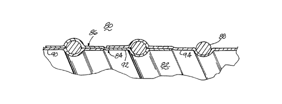
FIG. 9 shows a fragmentary, cross-sectional view of a fourth
embodiment of a lightweight hose 80 which comprises a tubular wall 82 having
at least
an inner ply 84 and an outer ply 86. The tubular wall 82 is reinforced by a
helical
member 88. The inner and outer plies 84 and 86 are formed by successive
helicaily-
oriented wraps of the ply material. For example, as shown in FIG. 9, a portion
of the
hose 80 is shown having inner and outer plies 84 and 86 formed by first wrap
90,
second wrap 92 and third wrap 94. It will be understood that a portion of each
wrap
farms an outer ply 86 and covers a single pitch of the helical member 88 and a
remaining portion of each wrap forms an inner ply 84 for the next successive
wrap of
the ply material.
FIG. 10 shows a magnified portion of FIG. 9 illustrating the interaction
between the first, second and third wraps 90, 92 and 94. It will be understood
that the
first wrap 90 has a leading edge 96 which is located adjacent a central
portion 98 of the
second wrap 92. In addition, the third wrap 94 has a trailing edge l 00 which
is also
located adjacent the central portion 98 of the second wrap 92. This
arrangement forms
a basic two-ply structure similar to that shown in FIGS. 1-2.
CA 02240469 1998-06-25
WO 97124543 PCT/US97/00232
_g_
FIG. I 1 shows a method of manufacture of the hose 80 illustrating the
helical wrapping method discussed above. A generally cylindrical mandrel 1 I O
is
shown, having a predetermined external diameter and extending at least as long
as the
desired length of the hose 80. The mandrel 1 I O can be provided with a
helical groove,
shown generally at 112, adapted to receive the helical member 88 therein. A
helical
core (not shown), such as a metallic or polymeric wire, can be wound around
the
mandrel 110 prior to a first piy of material to define a helical ridge, as
shown in FIG. 4.
Alternatively, and as seen in FIG. 7, the mandrel can be provided with a
helical
protrusion (not shown) for defining a helical ridge for forming a hose with
greater
flexing characteristics.
The mandrel 110 is first wrapped with a first wrap 90 of the ply material
around a single circumference of the mandrel. This first wrap 90 preferabiy
covers a
first pitch of the helical groove I 12. Next, a length of the reinforcing
member 88 is
Laid in the first pitch of the helical groove 112 covered by the first wrap
90. The
I5 mandrel 110 is then covered by a second wrap 92 of the ply material. A
portion of the
second wrap 92 covers the length of the reinforcing member 88 in the first
pitch of the
helical groove 112 and a next successive pitch of the helical groove 112. An
additional
length of the reinforcing member 88 is laid in the next successive pitch of
the helical
groove 112. This process repeats for the length of the mandrel 110. When the
last of
the ply material has been wrapped in this fashion over the Length of the
mandrel 110,
the entire structure is mechanically held and bonded as in the previous
methods
discussed herein. After bonding, the mechanical restraints are removed and the
hose 80
is removed from the mandrel 110.
FIGS. 12-13 show an alternative method of manufacture of a lightweight
hose. In the previous methods discussed, a mandrei of finite length is wrapped
and
then cured. The method of FIGS. 12-13 is a continuous method of manufacturing
a
hose wherein a short length of the hose is wrapped and cured in quick
succession and
then advanced so that a successive length of the hose can be formed. The
continuous
method described herein can form a hose of much greater length that a mandrel-
type
process because the Length of the hose is not limited by the length of the
mandrel.
As shown in FIGS. 12-13, a mandrel 120 is shown having a helical
groove 122. First spool 124 and second spool 126 are located adjacent the
mandrel 120
as well as a drive wheel 128 and a nozzle 130. The first spool 124 contains a
length of
CA 02240469 1998-06-25
WO 97124543 PCT/CTS97/00232
-10-
a reinforcing material 132, such as the reinforcing wire member of previous
embodiments described herein. The second spool 126 contains a length of a ply
material 134, such as the heat-seamable filin of previous embodiments
described
herein. The drive wheel 128 is located immediately adjacent the mandrel 120
and is
designed to drive the materials 132 and 134 from the spools 124 and 126 along
the
mandrel 120. The nozzle 130 has an exit port 136 located adjacent a point
between the
drive wheel 128 and the mandrel 120 and is preferably disposed between the
incoming
reinforcing material 132 and ply material 134. The nozzle 130 is fluidly
interconnected
to a source of heated pressurized air so that fluid dispensed from the exit
port 136 is
directed at the material on the mandrel 120.
The ply material l 34 on the second spool 126 is fed onto the mandrel
120. The ply material 134 is driven around the mandrel 120 by the drive wheel
128.
After a first length of the ply material 134 has been driven around a
circumference of
the mandrel 120 and covers a first pitch of the helical groove 122, a length
of the
reinforcing material 132 is fed from the first spool 124 into the helical
groove 122. The
ply material 134 is continually fed so that successive wraps of the ply
material l 34
overlap - a portion of each wrap covers the previously-laid length of the
reinforcing
material 132 in the helical groove 122 and the remaining portion of each wrap
covers a
successive pitch of the helical groove I22 to receive the next length of the
reinforcing
material 132. Heated, pressurized fluid is continually directed from the
nozzle 130 at
the recently-laid ply material 134 so that the ply material I34 is continually
bonded.
The continuous wraps of the ply material 134 and the reinforcing
material I32 form a hose of a structure similar to that shown in FIGS. 9-I 1.
The hose
cools as it travels along the length of the mandrel 120. It will be understood
that the
length of the hose can be accumulated as it travels offthe end of the mandrel.
It will be
also understood that the mandrel 120 can be formed with a helical protrusion
or pre-
wrapped with a helical core to form a helical ridge in the hose to increase
the bending
characteristics of the hose. The helical ridge allows additional flexing of
the hose by
preventing inward folds of the hose material during bending. Additional plies
of the
ply material can be provided by providing additional spoofs of the ply
material to create
a stiffer hose which is desirable at larger diameters to prevent collapse of
the hose
during use. The nozzle 130 heat seams the ply material I34 so that the
reinforcing
material 132 is contained in a pocket formed by successive overlapping
windings of the
CA 02240469 1998-06-25
WO 97124543 PCT/LTS97/00232
-il-
ply material 134. It will be further understood that the mandrel 120 need not
be
provided with the helical groove 122 so that a hose having a smooth interior
bore can
be manufactured thereon.
FIGS. 14-I6 show a connector, shown as an end cuff 140, having a first
end 142 and a second end 144 adapted to mount a conventional hose and a hose
assembly described herein, respectively. The first end 142 of the end cuff 140
comprises a cylindrical socket 146 and an optional annular groove I48 at an
interior
portion thereof. The second end of the end cuff 140 comprises a cylindrical
socket l 50
which is provided with internal threads I52 preferably formed by a helical
member
153, preferably configured with a similar pitch of the helical reinforcing
member of any
of the hose embodiments described herein. Alternatively, the helical member
153 can
be located adjacent or on an external surface of the cuff 140 so that the cuff
can be
threaded onto a conduit having internal threads thereon.
As shown in FIG. I5, the first end I42 can be interconnected with a
conventional fluid delivery conduit, shown generally at 154, having an annular
bead
156 at an axial end thereof. The conduit 154 can be mounted to the cuff 140 by
either
press-Patting the conduit I 54 into the first end I42 of the cuff 140 so that
the annular
bead 156 is located within the annular groove 148 of the cuff 140 or by
mounting a
conventional hose clamp around the first end 142 of the cuff 140 while the
conduit I 54
is located therein.
As shown in FIG. 16, the second end 144 of the cuff 140 is adapted to
threadingly receive a hose having a helical thread on an exterior surface
thereof. It will
be understood that the hose structures described herein have a helical
protrusion
formed by the helical reinforcing member mounted between plies in the hose
assembly.
A hose can be mounted to the second end 144 of the cuff I40 by threading the
helical
protrusion on the hose within the threads 152 on the interior portion of the
second end
l 44.
FIG. 17 shows a mandrel 160 adapted to form a cuff similar to that
shown in FIGS. 14-16. The mandrel 160 is a generally cylindrical member having
a
first end I 62 and a second end 164. The first end I 62 of the mandrel 160 can
be
shaped in any particular manner to conform to an interior portion of a
conventional
hose conduit such as the conduit 154 shown in FIG. 15. The second end 164 of
the
mandrel 160 is provided with a helical protrusion 168 which corresponds in
pitch to a
CA 02240469 1998-06-25
WO 97!24543 PCT/LTS97/00232
-12-
helical protrusion on a hose assembly, such as the embodiments of the hose
structures
described herein.
To manufacture the cuff 140 of FIGS. 14-16, a helical protrusion 168
can be provided on the mandrel I 60 of FIG. I 7. One or more layers of heat
seamable
material and elastomer-impregnated fabric can be wound around the mandrel 160
and
the helical protrusion 168 and bonded. In addition, a helical member, such as
that
shown at 153 in FIGS. 15-16, can be wrapped around a portion of the mandrel
160 at a
desired pitch, preferably in alternaxing pitch with the helical protrusion 168
thereon, to
form threads. Then, the formed cuff, shown as 140 in FIG. 17, can be removed
from
the mandrel 160. The cuff i40 can be formed from a heat seamable material,
silicone,
urethane or any other suitable material. A layer of film can be vulcanized to
the cuff
140 to provide a compatible material if the cuff is to be bonded to a hose
structure
made from a heat seamable material as described herein.
FIGS. i 8-19 show a T-connector 170 and a Y-connector 180,
respectively. In FIG. 18, the T-connector 170 comprises a cylindrical body 172
having
interior and/or exterior screw threads 174 at each end and further including
an
upwardly-extending cylindrical shell 176 having interior and/or exterior screw
threads
178 at a distal end thereof. In FIG. 9, the Y-connector i 80 comprises a
cylindrical
body 182 which forks at one end into first and second cylindrical paths 184
and 186.
The outer ends of the cylindrical body 182 and the cylindrical paths 184 and
186, each
are provided with external and/or internal screw threads 188. The screw
threads on the
T-connector 170 and the Y-connector I80 can be formed by an impregnated
helical
reinforcing member, as described herein, and are adapted to receive screw
threads on a
cuff 140 or to be threaded directly onto any of the hoses described herein or
any
suitable hose known in the prior art. The T-connector I70 and Y-connector 180
are
used for interconnecting two or more noses such as to divide a single flow
path into a
pair of branch flow paths or to converge a pair of flow paths into a single
flow path.
To make either connector I70 or 180, a shaped mandrel (not shown) in
the desired "T" or "Y" shaped is wrapped with a number of plies of material,
preferably
from one to eight, and encompassed by mechanical restraints. The wrapped
mandrel is
then bonded at a preselected temperature and time depending upon the
particular
material used for the connector 170, 180. The mandrel can include screw thread
formations on its surface which form screw threads on the connector. The
wrapped
CA 02240469 1998-06-25
WO 97/24543 PCT/US97/00232
-13-
mandrel is then cooled until the mechanical restraints can be removed. The
connector
170 or 180 is then removed from the mandrel and is ready for use.
It will be understood that the reinforcing member in the hose structures
described herein can be formed from a defonnable material which can be over-
bent to
define an elliptical, square, rounded, rectangular, or other desirable shape
as required
by a particular application.
It will be further understood that the cuffs and connectors described
herein can be formed as a transition piece or coupler to interconnect hoses
with
differently-shaped cross-sectional profiles. The transition pieces can be made
with
films in conjunction with rubber or polymer coated or impregnated fabrics as
required
by a particular application. A specially-shaped mandrel can be used in
conjunction
with a wrapping process as described above to create such a transition piece.
This
process, as in the above-described processes, does not require adhesive to be
disposed
between adjacent plies of material. As before, helical threads can be defined
on the
transition pieces for attachment to other hoses and conduits.
Reasonable variation and modification are possible within the spirit of
the foregoing specification and drawings without departing from the scope of
the
invention.