Note: Descriptions are shown in the official language in which they were submitted.
CA 02240476 1998-06-23
WO 98/18979 PCT/KR97100201
1
APPARATUS FOR COATING ZINC ON STEEL SHEET,
AND METHOD THEREFOR .
BACKGROUND OF THE INVENTION
1. Field of the invention
The present invention relates to an apparatus and a
method for coating zinc on steel sheets for use on
automobiles and electronic apparatuses. More
specifically, the present invention relates to an
apparatus and a method for coating zinc on steel sheets by
. using zinc powders.
2. Description of the prior art
Zinc performs an sacrificing action for steel to
extend the life expectancy of steel, and therefore,
conventionally zinc has been used in zinc-coating a steel
sheet. There are many kinds of zinc coating methods such
as hot dip galvanization, electroplating, and zinc
powder-using zinc coating. The zinc coated steel sheets
are mostly used as automobile body sheets and outer and
inner sheets of electronic apparatuses. They are
manufactured by electroplating or hot dip galvanization.
The reason is as follows. That is, when a steel strip is
continuously coated, not only the product quality but
also the productivity and the workability have to be
considered. In this respect, electroplating and hot dip
galvanization are advantageous.
Electroplating is carried out in the following
manner. That is, cold rolled steel sheets are made to
~ 30 undergo a batch annealing or a continuous annealing so as
to improve mechanical properties. Then, electroplating is
carried out within an electrolyte containing zinc ions,
thereby obtaining a zinc deposition layer of the target
CA 02240476 1998-06-23
WO 98!18979 PCTIKR97/0020I
2
. thickness. In this method, the mechanical properties
which have been obtained through heat treatments are not
degraded during the plating process. Further, the coated
amount (deposition thickness) is varied in accordance with
the applied electric power, and therefore, the coated
amount can be accurately controlled.
However, it has the following disadvantages. That
is, as the coated amount is increased, so much more
electric power is required. Consequently, the
productivity is aggravated in the case of a thick plating.
Therefore, electroplating is adopted in the case where
the coated amount is 40 g/mz or less for oiie face of steel
sheets. Meanwhile, the plating speed is limited by the
- limit current density, and therefore, if the
productivity is to be improved, the zinc coating chamber
has to be long. This becomes a facility burden. Because
of such limiting factors, electroplating should be
preferably carried out at a strip velocity of about 200
m/min and at a coated amount of 40 g/m2 or less for one
face of the steel sheet.
Meanwhile, hot dip galvanization is carried out in
the same facility as that of the annealing. Therefore the
manufacturing cost becomes lower, and a thick zinc
coating is possible. However, it has the following
disadvantages. That is, a sink roll and a guide roll
which are immersed in a hot dipping pot are corroded, and
therefore, they have to be replaced periodically.
Further, as the line speed becomes fast, so much the
resistivity of the melted zinc is increased. Therefore,
the sink roll cannot move synchronously with the steel
sheet to produce slips, and therefore, the surface of
the steel sheet may be scratched so much as to lead to a
product defect. Further, as the line speed is increased,
CA 02240476 2000-09-O1
3
or as the coated thickness is decreased, splashes are
increased during an air wiping, with the result that the
generation of dross is increased. Besides, if the zinc
adhered on the surface is to be solidified, some cooling
period is required, and therefore, the velocity of the
steel sheet is limited to about 200 m/min. Further, the
adjustment of the coated thickness is difficult, and
therefore, the manufacturing becomes difficult if the
coated amount per face is less than 40 g/mz.
l0 Meanwhile, a method for coating zinc by using zinc
powders is already known in the prior art.
This method is illustrated in FIG. 1. As shown in
this drawing, an object to be coated (steel sheet) 1 is
heated to above the melting point of the powder metal,
and zinc powders loaded on a gas are spouted by means of
a spouting nozzle 6 onto the object 1 within a zinc
coating chamber 3 containing a reducing atmosphere. Thus
the zinc powders are melt-adhered on the steel sheet 1,
thereby zinc-coating the steel sheet.
20 In FIG. 1, reference codes 4 and 5 indicate sealing
devices.
In this method, a reducing atmosphere is used, and
therefore, a flux does not have to be used. Further,
compared with the hot dip galvanization, the air wiping
and the management of the melt composition are not
required, and the dross generation does not occur.
However, in the case of Japanese Patent Application
Laid-open No. Hei-5-311388, the zinc powders from the
powder storage chamber are not screened but directly
spouted into-the zinc coating chamber. Therefore, large
particles and coarse secondary particles can adhere on the
steel sheet, with the result that the coated layer
CA 02240476 1998-06-23
WO 98/18979 PCT/KR97/00201
4
becomes irregular.
Meanwhile, another zinc coating method is disclosed
in which an object to be coated is heated to 775°F (413°C)
- 820°F (438°C), and zinc powders or a zinc melt is
spouted, so that zinc would be coated on steel sheets (CA
866153 {7113).
In this method, however, a flux is spouted together
with the zinc powders to prevent the oxidation of the
steel sheet. Further, in order to improve the adherence
10 of zinc, electrostatic charges of opposite polarities are
provided on the zinc powders and the object to be coated.
In this method, owing to the mechanical spouting
force and the electrostatic attractions, a large coated
amount can be easily obtained. Further, it can be
applied to a complicated steel structure, but when it is
applied to a continuous zinc coating of a steel strip,
the following problems occur. (1) The high voltage
electrostatic charges of opposite polarities are dangerous
to workers. (2) There are necessarily loosely adhered
zinc particles after the zinc coating, and these
particles adhere on various rolls to cause defects called
"dent". (3) Zinc powders are released into the external
air to aggravate the working environment.
Further, there are other disclosures in which
electrostatic charges are utilized in coating zinc powders
(U. S. Patents 5,384,165 and 5,551,981).
In these methods, zinc powders are made to adhere on
steel sheets by utilizing electrostatic charges, and
then, the steel sheets are heated to convert the adhered
zinc powders to a coated layer.
The apparatus far these methods is illustrated in
FIG. 2. As shown in this drawing, the apparatus includes
a fluidized bed 18 of zinc powders, and a cooling device
CA 02240476 1998-06-23
WO 98!18979 PCT/KR97l00201
24 and a heating device 21 disposed above the fluidized
bed 18. A steel sheet immersed in fluidized bed 18 is
~ made to shift its advancing direction upward to be heated
by the heating device 21, so that the zinc powders would -
' 5 be melted. The melted zinc powders are reflowed, and
then are cooled.
In FTG. 2, reference code 10 indicates a housing,
16 indicates a strip bending roll, 17 indicates a fall
space, 17A indicates a plate as a part of an
electrostatic charge circuit, 17B indicates a controller,
indicates a top deflector roll.
In these U.S. patents, steel sheets can be coated
without much modifying the existing melting facility, but
have the following disadvantages.
15 (1) When the electrostatically charged metal powders
contact with the steel sheet, the surface charges are
transferred to the steel sheet so as to be grounded and to
disappear. Therefore, the attractive force of the
electrostatic charges which is to act as the adhering
20 force between the steel sheet and the zinc powder is
dissipated. Therefore, the zinc powders depart from the
_ surface of the steel sheet, and therefore, there is a
limit in the increase of the coated thickness.
( 2 ) The roller is immersed in the fluidized bed of
zinc powders, and therefore, when the steel sheets
moves, the zinc powders intrude into between the roller
and the steel sheet, so that the zinc powders may adhere
. on the roller. Particularly, zinc powders speedily
undergo sintering reactions above 250°C. Therefore, the
zinc powders which have intruded into between the steel
_sheet and the roller undergo a sintering reaction owing to
the latent heat of the steel sheet. As a result, coarse
particles may be formed, and the dent phenomenon becomes
CA 02240476 1998-06-23
WO 98/18979 PCT/dCR97/00201
6
more serious.
(3) The fine zinc particles of 5-15 um which are used
in the above patents are not well fluidized, but
agglomerations occur. Therefore, the zinc particles of
the fluidized bed are liable to be irregular, and
therefore, if the steel sheet is put into the fluidized
bed, a uniform coated layer cannot be obtained.
Further, if a reflowing is carried out after the
adherence of the zinc powders, a volume contraction
occurs as in the case of the powder metallurgy.
Therefore, the coated layer may look as if the steel
sheets has cracked. Further, if the reflowing is
imperfectly carried out, the residual zinc powders of the
surface will adhere on the roller so as to form a dent
defect.
SUMMARY OF THE INVENTION
In order to solve the above described disadvantages
of the conventional techniques, the present inventors
carried out researches and studies, and based on the
result of the researches and studies, the present
inventors proposes the present invention.
Therefore it is an object of the present invention to
provide a zinc coating apparatus and a method therefor,
in which a fluidized bed forming chamber is provided to
fluidize zinc powders in carrying out a zinc coating on a
heated steel sheet, so that not only a uniformly coated
layer but also a thick coated layer can be obtained.
It is another object of the present invention to
provide a zinc coating apparatus and a method therefor, -
in which a fluidized bed forming chamber is provided to
fluidize zinc powders, and the fluidized zinc powders are
electrostatically charged to coat zinc on a heated steel
CA 02240476 2000-09-O1
7
sheet, so that not only a uniformly coated layer but also
a thick coated layer can be obtained, and that an
aesthetically superior coated layer can be obtained.
In achieving the above objects, an apparatus for
continuously coating zinc on a steel sheet according to the
present invention, comprises:
a fluidized bed forming chamber for forming a
fluidized bed of zinc powders by suspending the zinc
powders in a gas;
a zinc coating chamber which receives the fluidized
bed of zinc powders through a powder inlet tube from said
fluidized bed forming chamber, wherein a steel sheet heated
by a heating means is passed through the fluidized bed of
the zinc powders, and wherein the zinc powders melt-adhere
on the steel sheet during a passing of the steel sheet
through the fluidized bed of zinc powders;
a cyclone for separating the zinc powders from the gas
after recovery of the zinc powders from said zinc coating
chamber, to discharge the gas, and to return the separated
zinc powders to said fluidized bed forming chamber, wherein
said cyclone is in connection with both said zinc coating
chamber and said fluidized bed forming chamber;
a deflector roll for shifting an advancing direction
of the steel sheet after its admittance into said zinc
coating chamber, wherein said deflector roll is located
upstream form said zinc coating chamber;
a tension roll for shifting an advancing direction of
a zinc coated steel sheet, wherein said tension roll is
located downstream from said zinc coating chamber;
said zinc coating chamber comprising: said powder
inlet tube connected from a side wall of said zinc coating
CA 02240476 2000-09-O1
8
chamber to said fluidized bed forming chamber to inject the
fluidized zinc powders into said zinc coating chamber; a
gas inlet tube for forming a turbulent flow of the zinc
powders and for preventing a leakage of the zinc powders;
and a recovering tube for recovering uncoated zinc powders;
said gas inlet tube being disposed above said powder
inlet tube, and said recovering tube being disposed below
said powder inlet tube;
said recovering tube being connected between said zinc
coating chamber and said cyclone, and a suction pump being
connected to said cyclone;
a separating plate provided within said zinc coating
chamber, for making uncoated zinc powders flow to said
recovering tube, and for preventing the zinc powders from
flowing to a stabilizing roll; and
a stabilizing roll disposed below said separating
plate.
In another aspect of the present invention, the
apparatus for continuously coating zinc on a steel sheet
according to the present invention includes:
a fluidized bed forming chamber for forming a
fluidized bed of zinc powders by suspending the zinc
powders in a gas;
a zinc coating chamber for receiving the fluidized
zinc powders from said fluidized bed forming chamber
through a powder spouting means, and causing the fluidized
zinc powders to melt-adhere on a heated steel sheet;
a cyclone for separating the zinc powders from the gas
after recovery of the zinc powders from said zinc coating
chamber, to discharge the gas, and to return the separated
CA 02240476 2000-09-O1
9
zinc powders to said fluidized bed forming chamber, wherein
said cyclone is in connection with both said zinc coating
chamber and said fluidized bed forming chamber;
a deflector roll for shifting an advancing direction
of the steel sheet after its admittance into said zinc
coating chamber, wherein said deflector is located upstream
from said zinc coating chamber;
a tension roll for shifting an advancing direction of
a zinc coated steel sheets wherein said tension roll is
located downstream from said zinc coating chamber;
said zinc coating chamber comprising a powder spouting
means connected from a side wall of said zinc coating
chamber to the fluidized bed forming chamber to spout the
fluidized zinc powders into said zinc coating chamber;
said zinc coating chamber further comprising a
recovering tube connected to said cyclone, for recovering
uncoated zinc powders; and
one or more electrodes provided in said zinc coating
chamber, for electrostatically charging the zinc powders,
said electrodes being connected to a voltage generating
device.
In still another aspect of the present invention,
the method for continuously coating zinc on a steel sheet
by making the steel sheet pass through a zinc coating
chamber according to the present invention, includes the
steps of
supplying fluidized zinc powders of a fluidized bed
to the zinc coating chamber, and injecting an inert gas
or a reducing gas into the zinc coating chamber through a
3o side wall of the zinc coating chamber to form a fluidized
bed within the zinc coating chamber;
CA 02240476 2000-09-O1
passing a steel sheet heated to a temperature of 420-
730°C through the fluidized bed within the zinc coating
chamber to melt-attach the zinc powders on the steel sheet
so as to form a coated layer;
reheating the zinc powder adhere steel sheet at a
temperature of 420-650°C for 1-20 seconds to make
imperfectly adhered zinc powders melt-adhered on the
surface of the steel sheet so as to form a coated layer;
and
10 discharging residual uncoated zinc powders from a
bottom portion of the zinc coating chamber together with
a gas by a cyclone, to separate the zinc powders from the
gas so as to discharge the gas and so as to return the
separated zinc powders to a fluidized bed forming chamber.
In still another aspect of the present invention, a
method for continuously coating zinc on a steel sheet by
making the steel sheet pass through a zinc coating chamber
according to the present invention comprises the steps of:
receiving zinc powders from a powder supply device,
and fluidizing the zinc powders within a fluidized bed
forming chamber by introducing a gas into the fluidized bed
forming chamber;
providing the fluidized zinc powders from said
fluidized bed forming chamber to a zinc coating chamber by
means of a powder spouting device to form a fluidized bed
within said zinc coating chamber;
charging the zinc powders of the fluidized bed
positively or negatively;
heating a steel sheet to 420-730°C and grounding the
steel sheet, and making the steel sheet pass through the
CA 02240476 2000-09-O1
l0a
fluidized bed to make the charged zinc powders melt-adhere
on the steel sheet;
sending a residual zinc powders of a bottom portion of
said zinc coating chamber to a cyclone together with a gas
to separated the zinc powders from the gas, so as to
discharge the gas, and so as to return the separated zinc
powders to a powder supply device.
The above method further includes the step of:
forming a coated layer by melt-coating the zinc powders on
the steel sheet, and then, carrying out a reheating at
a temperature of 420 - 650°C for 1 - 20 seconds to make
residual uncoated zinc powders melt-adhere on the steel
sheet.
BRIEF DESCRIPTION OF THE DRAWINGS
The above objects and other advantages of the present
invention will become more apparent by describing in
detail the preferred embodiment of the present invention
with reference to the attached drawings in which:
FIG. 1 is.a schematic illustration of a conventional
zinc coating apparatus;
CA 02240476 1998-06-23
WO 98/18979 PCT/KR97/00201
11
FIG. 2 is a schematic illustration of another
conventional zinc coating apparatus;
' FIG. 3 illustrates an embodiment of the zinc coating
apparatus according to the present invention;
FIG. 4 illustrates another embodiment of the zinc
coating apparatus according to the present invention;
FIG. 5 is a detailed illustration of a portion A of
FIG. 4;
FIG. 6 is a graphical illustration showing the
variation of agglomeration of the zinc powders versus the
temperature of the fluidized bed within the zinc coating
chamber;
FIG. 7 is a graphical illustration showing the
variation of the coated amount versus the variation of the
gas flow rate; and
FIG. 8 is a graphical illustration showing the
variation of the coated amount versus the variation of the
voltage of the electrode.
DETAILED DESCRIPTION OF THE PREFERRED EMBODIMENT
FIG. 3 illustrates a first embodiment of the zinc
coating apparatus according to the present invention.
As shown in this drawing, the apparatus includes:
a zinc coating chamber 120 for forming a fluidized
bed of zinc powders, for passing a heated steel sheet
(steel strip) 101 through the fluidized bed of the zinc
powders, and for making the zinc powders melt-adhere on
,, the steel sheet during the passing of the steel sheet
through the fluidized bed;
a fluidized bed forming chamber 140 for forming a
fluidized bed of the zinc powders by making the zinc
powders suspended by spouting a gas;
a cyclone 150 for separating the zinc powders from
CA 02240476 1998-06-23
WO 98/18979 PCT/Kgt97/00201
12
the gas after recovery of them from the zinc coating
chamber 120, to discharge the gas, and to return the
separated zinc powders to the fluidized bed forming
chamber 140;
a deflector 122 for shifting the advancing direction
of the steel sheet after its admittance into the zinc
coating chamber 120; and
a tension roll 132 for shifting the advancing
direction of a zinc coated steel sheet.
A means for heating the steel sheet may be an
annealing furnace 110 as shown in FIG. 3.
The zinc coating chamber includes a powder spouting
tube 143 connected from a side wall of the zinc coating
chamber 120 to the fluidized bed forming chamber 140 to
inject the fluidized zinc powders into the zinc coating
chamber 120.
Further, on a side wall of the zinc coating chamber
120, there is provided a gas inlet tube 124 for forming
a turbulent flow of the zinc powders and for preventing a
leakage of the zinc powders. The zinc powders are
supplied from a powder supply tube 143, and the gas inlet
tube 124 is disposed above the powder supply tube 143.
On a side wall of the zinc coating chamber 120,
there is further connected a recovering tube 152 for
sending uncoated and descending zinc powders and the gas
to the cyclone 150.
The recovering tube 152 should preferably include an
inclined portion 152A, and this inclined portion 152A
should be constituted such that it can facilitate the
recovery of the zinc powders.
The zinc-coating chamber 120 includes a separating
plate 126. This separating plate 126 makes the uncoated
zinc powders flow smoothly to the recovering tube 152,
CA 02240476 1998-06-23
WO 98!18979 PCT/KR97100201
13
and prevents the zinc powders from flowing through a
recovering tube connecting portion to the lower portion of
- the zinc coating chamber 120.
Beneath the separating plate 126, there is disposed
' 5 a stabilizing roll 123.
The upper portion of the_ fluidized bed forming
chamber 140 is connected to a hopper 144 which supplies
the zinc powders. To the bottom of the fluidized bed
forming chamber 140, there is connected a gas supply tube
141 which is connected to a gas supply source (not shown
in the drawings). Below the fluidized bed forming chamber
140, there can be disposed a porous gas dispersing plate
142 which disperses the gas from the gas supply tube 141
to obtain a uniform fluidized bed.
The fluidized bed forming chamber 140 and the cyclone
150 can be provided in the number of one or more. In the
,_ present invention, even if a single fluidized bed forming
chamber 140 is installed, a plurality of powder inputting
tubes 143 can be connected to it, so that the zinc
powders can be inputted into the zinc coating chamber 120
from a plurality of points.
The cyclone 150 is connected to a suction pump 156,
and the suction pump 156 sucks the uncoated zinc powders
and the gas from the zinc coating chamber 120.
A filter 154 should be preferably installed between
the cyclone 150 and the suction pump 156, so that the
zinc powders remaining in the gas after the gas-powder
separation by the cyclone 150 can be captured.
The uncoated zinc powders remaining on the coated
_ 30 surface of the steel sheet should be converted into a zinc
coated layer. For this purpose, the coated steel sheet
is heated. ~In order to carry out the heating, a
reheating furnace 130 should be preferably installed
CA 02240476 1998-06-23
WO 98/18979 PCT/iCR97/00201
14
between the zinc coating chamber 120 and the tension roll
I32.
Valves 144a and 151 are installed respectively under
the hopper 144 and the cyclone 150.
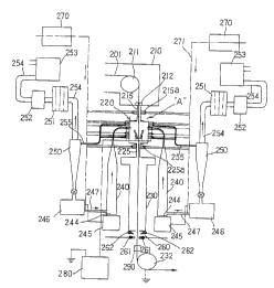
In another embodiment of the present invention, the
apparatus for continuously coating zinc on a steel sheet
according to the present invention as shown in FIG. 4
includes:
a zinc coating chamber 220 for making zinc powders
melt-adhere on a heated steel sheet (strip) 201 to form a
coated layer;
a fluidized bed forming chamber 240 for forming a
fluidized bed of the zinc powders by making the zinc
powders suspended by spouting a gas;
a cyclone 250 for separating the zinc powders from
the gas after recovery of them from the zinc coating
chamber 220, to discharge the gas, and to return the
separated zinc powders to the fluidized bed forming
chamber 240;
a deflector 211 for shifting the advancing direction
of the steel sheet after 'its admittance into the zinc
coating chamber 220; and
a tension roll 232 for shifting the advancing
direction of a zinc coated steel sheet.
The means for heating the steel sheet may consist of
an annealing furnace 210 as shown in FIG. 4.
The zinc coating chamber 220 includes a powder
spouting device 223 connected from a side wall of the zinc -
coating chamber 220 to the fluidized bed forming chamber
240 to spout the zinc powders into the zinc coating
chamber 220.
The powder spouting device 223 should preferably
include: a powder carrying tube 223c connected to the
CA 02240476 1998-06-23
WO 98118979 PCT/KR97/0020I
fluidized bed forming chamber 240; an injection pump 223b
connected to the powder carrying tube 223c; and a powder
spouting nozzle 223a for spouting the zinc powders from
the injection pump 223b into the zinc coating chamber 220.
5 The power spouting device 223 is installed in the
number of two on the opposite side walls of the zinc
coating chamber 220.
Further, the zinc coating chamber 220 should be
provided with one or more of electrodes for
10 electrostatically charging the zinc powders.
As shown in FIG. 5, a pair of sharp electrodes 228
should be preferably provided on the sides walls of the
zinc coating chamber 220 oppositely facingly. More
preferably, a pair of the sharp electrodes 228 should be
15 provided on the side walls of the zinc coating chamber
220, and at the same time, a pair of net type electrodes
229 should be provided mutually facingly across the
advancing steel sheet within the zinc coating chamber 220.
These electrodes are connected to a high voltage
generator 280.
These electrodes are for electrostatically charging
the zinc powders with negative or positive charges.
A recovering tube 227 which is connected to the
cyclone 250 is also connected to a lower portion of the
side wall of the zinc coating chamber 220, for recovering
the uncoated zinc powders. The recovering tube 227 can be
connected not only to the zinc coating chamber 220 but
also to an upper portion of the side wall of the powder
spouting device 223.
An upper sealing chamber 215 is installed between the
annealing furnace 210 and the zinc coating chamber 220,
while a lower sealing chamber 225 is installed between the
zinc coating chamber 220 and the reheating furnace 230.
CA 02240476 1998-06-23
WO 98/18979 PCT/HIZ97/00201
16
The upper sealing chamber 215 communicates to the
zinc coating chamber 220. The-.isolation between the
annealing furnace 210 and the zinc coating chamber 220
should preferably be done by a pair of sealing rolls 212
which prevent lateral oscillations of the steel sheet,
electrically ground the steel _sheet, and seal the
atmosphere of the annealing furnace 210.
A pair or more of gas spouting nozzles 215a should be
preferably provided on the upper sealing chamber 215, so
that the zinc powders can be prevented from floating up to
the sealing roll 212, and that the internal pressure of
the zinc coating chamber 220 can be adjusted.
The lower sealing chamber 225 should be preferably
provided with a pair or more of gas spouting nozzles 225a
to inject an atmospheric gas so as to adjust the internal
pressure of the zinc coating chamber 220.
The upper sealing chamber 215 and the zinc coating
chamber 220 should be insulated from each other by means
of an insulator 215b. The lower sealing chamber 225 and
the zinc coating chamber 220 should be insulated from each
other by means of an insulator 225b.
If the insulators are provided as described above,
then the walls of the zinc coating chamber are charged
with the same polarity as that of the zinc powders, and
therefore, the zinc powders can be prevented from being
adhered on the walls of the zinc coating chamber.
Within the zinc coating chamber, the flow of the
zinc powders should be prevented from being lamella within
the internal atmosphere. For this purpose, a, pair or
more of gas spouting nozzles 226a should be preferably
installed on the upper portion of the side wall of the
zinc coating chamber 220. Further, a pair or more of gas
spouting nozzles 226b should be preferably installed on
CA 02240476 1998-06-23
WO 98/18979 PCT/HIZ97/00201
17
the side wall of the zinc coating chamber 220 between the
powder spouting nozzle 223 and the powder recovering tube
227.
As shown in FIG. 4, a gas discharge tube 254 is
- 5 connected to the top of the cyclone 250, and the gas
discharge tube 254 is connected to a suction pump 253
which transfers the gas and the uncoated zinc powders from
the zinc coating chamber 220 to the cyclone 250.
The gas discharge tube 254 includes a back filter 251
and a dust collector 252, and the back filter 251 filters
the discharge gas, while the dust collector 252 collects
fine zinc powders after their passing through the back
filter 251.
Meanwhile, the bottom of the cyclone 250
communicates to the powder supply device 246, and
therefore, the zinc powders which have been separated
from the gas are carried to the powder supply device 246.
The lower side wall of the fluidized bed forming
chamber 240 is connected to the powder supply device 246
through the powder supply tube 247, so that the zinc
powders can be supplied to the fluidized bed forming
chamber 240. A gas supply part 245 is connected to the
bottom of the fluidized bed forming chamber 240, for
supplying the fluidizing gas to the fluidized bed forming
chamber 240.
A porous gas dispersing plate 244 should be
preferably installed in the lower portion of the fluidized
bed forming chamber 240, so that the gas supplied from
the gas supply part 245 can be uniformly dispersed.
The fluidized bed forming chamber 240 and the cyclone
250 can be provided in the number of one or more.
In the present invention, even in the case where.a
single fluidized bed forming chamber 240 is installed, a
CA 02240476 1998-06-23
WO 98/18979 PCT/KIt97/00201
18
plurality of the powder spouting device 223 can be
connected to the fluidized bed forming chamber 240, so
that the zinc powders can be spouting from a plurality of
points into the zinc coating chamber 220.
A reheating furnace 230 should be preferably -
installed between the zinc coating chamber 220 and the
tension roll 232, so that the coated steel sheet can be
reheated, and that the residual zinc powders can be
converted into a coated layer.
Meanwhile, in the case where the reheating furnace
230 is installed beneath the zinc coating chamber 220, a
cooling device 260 can be installed beneath the reheating
furnace 230. This cooling device 260 should preferably
consist of an air spouting nozzle 262 for forming an air
curtain above a water spouting nozzle 261.
A washing device 290 having a brush for washing the
surface of the steel sheet can be installed beneath the
water spouting nozzle 261 of the cooling device 260. In
the case where this washing device 290 is installed, the
20 residual zinc powders are removed from the surface of the
steel sheet, and therefore, the workability is improved.
Further, in the case where the reheating furnace 230
is installed, a holding chamber can be installed, so
that the temperature of the steel sheet under the
reheating furnace can be maintained at 500 - 650°C to
subject the coated layer to an alloying treatment.
Meanwhile, in the present invention, a gas heating
device 270 should be preferably installed to heat the
supplied gas to a certain temperature level.
Now the operation of the zinc coating apparatus of
the present invention will be described referring to FIGS .
4 and 5.
First, the steel sheet 201 is heat-treated in the
CA 02240476 1998-06-23
WO 98/18979 PCT/KR97/00201
19
annealing furnace 210, and the temperature of the steel
sheet is adjusted to 420 - 730°C. This steel sheet enters
into the zinc coating chamber 220 by the help of the
deflector roll 211 and the tension roll 232. Meanwhile, -
the zinc powders are supplied from the powder supply
device 246 through-the powder supply tube 24? into the
fluidized bed forming chamber 240 to be suspended there.
Then the zinc powders are transferred through the powder
carrying tube 223c, the injection pump 223b anal the
powder spouting nozzle 223a into the zinc coating chamber
220. Then the zinc powders are first charged by an
electrode 228 which is disposed near the powder spouting
nozzle 223a so as to adhere on the steel sheet. Owing to
a nitrogen gas or nitrogen-hydrogen gas mixture which is
spouted through the gas spouting nozzle 226b of the zinc
coating chamber 220, layered flows are prevented.
Further, the zinc powders are completely charged by the
net type electrode 229, with the result that the adhering
efficiency is improved. Under this condition, the gas
and the residual uncoated zinc powders are sucked into the
recovering tube 227 so as to double the turbulent flow
effect. In-order to improve the efficiency of the flow of
the zinc powders, the pressure and the flow rate of the
fluidized carrier gas and the auxiliary gas of the ventury
tube are properly adjusted. The coated amount during the
zinc coating is adjusted by the supplied amount of the
zinc powders, by the amount of the gas spouted into the
fluidized bed and the ventury tube, and by the voltage
supplied to the electrode.
- 30 The residual zinc powders after the zinc coating are
discharged through the recovering tube 227 and the gas
discharge tube 254 to the outside of the zinc coating
chamber 220 by the suction pump 253. Then they are
CA 02240476 1998-06-23
WO 98!18979 PCT/KR971~0201
transferred to the cyclone 250, and are separated into
the gas and the zinc powders. The separated zinc powders
are reinputted through a valve into the powder supply -
device, while the separated gas is discharged through the
5 back filter 251 and the dust collector 252. In order to
prevent the zinc powders from being mixed into the
annealing furnace 210, a nitrogen or nitrogen-hydrogen
mixture gas is spouted through the gas spouting nozzle
215a of the upper sealing chamber 215 so as to form a gas
10 curtain, and to adjust the internal pressure of the zinc
coating chamber 220. Further, the oscillations of the
steel sheet have to be prevented, the steel sheet has to
be grounded, and the atmospheres of the annealing furnace
210 and the zinc coating chamber 220 have to be isolated
15 from each other. For these purposes, the sealing roll
212 is driven. In the lower sealing chamber 225 of the
zinc coating chamber 220 also, a nitrogen gas or
nitrogen-hydrogen mixture gas is spouted through the gas
spouting nozzle 225a so as to form a gas curtain, and to
20 adjust the internal pressure of the zinc coating chamber
220. The coated steel sheet is heated by the reheating
furnace 230 to make the imperfectly adhered zinc powders
melt-adhere on the steel sheet. Further, if necessary,
the coated steel sheet is subjected to a zinc-iron
alloying reaction within a holding chamber. When cooling
the reheated steel sheet, if a water cooling method is
adopted, the cooling efficiency is improved. The steam
which is generated during the water cooling is not fed
into the zinc coating chamber but discharged to the
outside by the help of the air curtain of the cooling
device. Depending on cases, the coated steel sheet can
be washed before it is contacted with the tension roll,
thereby completely removing the loosely adhered zinc
CA 02240476 1998-06-23 -
WO 98/18979 PCT/KR97/00201
21
powders. The nitrogen or nitrogen-hydrogen mixture gas is
heated by the gas heating device 270 before being supplied
through the gas supply tube so as to be used in the zinc
coating.
Now the method for coating zinc on the steel sheet
according to the present invention will be described in
detail.
In the present invention, a steel sheet which has
been heated to a proper temperature is contacted with
solid phase metallic zinc powders which are suspended.
Thus owing to the latent heat of the steel sheet, the
zinc powders adhere on the surface of the steel sheet
perfectly or imperfectly. Therefore, a coated layer is
formed, and in the case where the adherence is imperfect,
a reheating is carried out, so that a perfect adherence
can be realized through a melt-adherence.
Specifically, in the present invention, the
desirable conditions for forming a perfect coated layer
are as follows.
1) Oxides should not exist on the surfaces of the
steel sheet, so that the coated layer would closely
adhere on the steel sheet.
2) The steel sheet has to have a latent heat enough
to ensure a perfect melt-adherence of the zinc powders on
the steel sheet.
In a state with the Items 1 and 2 satisfied, if the
following conditions are met, then a satisfactory quality
in the zinc coated steel sheet can be obtained.
3 } In order to obtain a uniform coated layer, the
particles of the zinc powders should have less than a
certain size.
4} The adherence of the coated layer should be
superior, the Item 1 has to be met, and an excessive
CA 02240476 1998-06-23
WO 98/18979 PCT/KR97/00201
22
formation of an alloy layer (I' phase) on the boundary
between the coated layer and the steel sheet should be
inhibited.
5) In the zinc powder adhered layer, imperfect
adherences can easily occur, and these imperfectly
adhered powders should be removed or made to melt-adhere
for ensuring the quality of the zinc coated sheet.
In the present invention, the conditions for meeting
the above Items 1-5 are as follows.
If the Item I is to be met, the atmosphere which is
used during the heating of the steel sheet has to be a
reducing gas or a non-oxidizing gas. In the steel
manufacturing industry, this condition can be satisfied
in the continuous annealing.furnace which is used in
manufacturing cold-rolled steel sheets. Generally, the
used gases are mixtures of nitrogen plus hydrogen or
nitrogen plus carbon monoxide. In the general continuous
annealing furnace, the formation of oxides rarely occurs,
and therefore, the Item 1 can be sufficiently satisfied.
If the Item 2 is to be met, the temperature of the
-- steel sheet should be preferably limited to 420 - 730°C,
and the reason is as follows. That is, at a temperature
of 419°C which is the melting point of zinc, there can
occur imperfect adherences or adherences through diffusion
reactions. However, if a sound coated layer is to be
ensured, the repeating step is necessary.
At the repeating step, when the zinc powders melt-
adhere, the external appearance of the steel sheet may be -
aggravated due to the volume contraction. Further, too
much load is imposed on the repeating furnace. On the '
other hand, if the steel sheet is heated to above 730°C,
the mechanical properties may be aggravated, and a zinc-
iron alloying reaction is excessively promoted, with the
CA 02240476 1998-06-23
WO 98/18979 PCT/KR97/00201
23
result that the adherence of the coated layer is adversely
affected.
- If the Item 3 is to be met, the average particle
size of the zinc powders should be preferably limited to
less than 45 ~m (-325 mesh). In the case where the coated
amount is as low as 50 g/mZ, if the average particle size
is more than 45 ,um, then the adhered powder amount is too
small, with the result that some parts of the steel sheet
may be exposed bare, thereby giving a non-uniform zinc
coating.
As to the Item 4, when the zinc powders adhere on
the heated steel sheet, the iron atoms and the zinc atoms
diffuse mutually to form an alloy layer. If this is to be
prevented, it is known that the formation of Zn-A1
compounds or the like on the boundary between the coated
layer and the steel sheet is effective. If this is to be
ensured, ~ the aluminum content within the zinc powders
should be preferably limited to 0.1 - 0.7 wt~.
If the A1 content is less than 0.1~, an alloy layer
is developed on the boundary, and therefore, the close
adherence in the zinc coating is aggravated. On the other
hand, if the A1 content is more than 0.7$, although
there is no problem in the formation of the coated layer,
the formed coated layer is a Zn-A1 alloy layer rather than
a pure zinc layer. Therefore, the coated sheet is not
suitable for use in automobiles and electronic
apparatuses.
If the Item 5 is to be met, the steel sheet should
be subjected to a reheating after its passage through the
zinc coating chamber. If this step is omitted, the
imperfectly adhered zinc powders can be transferred to
various rolls to cause defects such as dent or the like.
As to the reheating conditions, the reheating is carried
CA 02240476 1998-06-23 -
WO 98118979 PCTIKR97/00201
24
out at a temperature of 420 - 650°C for 1 - 20 seconds.
More precise conditions are decided by the composition of
the target coated layer. That is, if the target coated
layer is a pure zinc layer, then the steel sheet may be
heated to 420 - 500°C. Then the zinc powders are
completely melt-adhered to form an acceptable zinc coated
layer. When a Zn-Fe alloy coated layer is aimed at, the
steel sheet is heated at 500 "' 650°C for 10 "' 20 seconds
so as to promote the alloying reactions. Thus the loosely
adhered zinc powders are made to melt-adhere, as well as
promoting the alloying reactions. In this way, the
reheating is carried out suitably with the composition of
the coated layer after the steel sheet has passed through
the zinc coating chamber as described above. Therefore,
the loosely adhered zinc powders are converted into a
coated layer, and at the same time, a coated layer
having the target Fe content can be obtained.
In the present invention, the interior of the zinc
coating chamber has to be filled with an inert gas or a
reducing gas, and has to be filled with fluidized zinc
powders. The temperature of the zinc coating chamber
should be preferably limited to below 250°C.
If the zinc powders are contacted to the steel sheet
based on the general method such as spouting or the like,
locally non-uniform portions will necessarily occur due to
the differences in the flow pattern, thereby making it
difficult to obtain a uniform coated layer. Therefore,
the present inventors studied on the method of contacting ,
the zinc powders to the steel sheet, and as a result,
found the following fact. That is, if fluidized zinc
powder s like a fog are uniformly dispersed within the zinc
coating chamber, and if the steel sheet is made to pass
through the fog, then a uniform coated layer could be
CA 02240476 1998-06-23
WO 98/18979 PCT/KR97/00201
obtained.
Under this condition, the gas which is used for
- forming the fluidized bed of the zinc powders should be a
reducing gas or a non-oxidizing gas. Otherwise,
' 5 oxidation reactions occur on the surfaces of the steel
sheet, and consequently, the adherence of the coated
layer is aggravated. Further, if the temperature of the
fluidized bed of the zinc powders exceeds 250°C, then the
fluidized zinc powders are liable to be agglomerated as
10 shown in FIG. 6, with the result that the stable
fluidizing is destroyed. Consequently, the zinc
particles adhere on the manufacturing facility in the form
of agglomerates.
- After satisfying the Items 1, 2, 3, 4 and 5, if the
I5 zinc coating method is to have an efficiency, the desired
coated amount has to be obtained in an easy manner.
In the present invention, if the above conditions
are all met, it was confirmed as shown in FIG. 7 that the
coated amount can be adjusted by adjusting the flow rate
20 of the gas which is used for forming the fluidized zinc
bed. FIG. 7 is a graphical illustration showing the
variation of the coated amount versus the variation of the
gas flow rate, when the temperatures of the coated steel
sheets are different. This is an -evidence to the fact
25 that, if all the conditions of the present invention are
satisfied, as the gas flow rate increases, the movements
of the zinc powders become brisk, and the zinc particles
collide with the steel sheet in an increased amount. That
is, if the temperature of the steel sheet is below 420°C,
the diffusion velocities become slow, and therefore, the
coated speed becomes slow. Therefore, a coated amount of
100 g/m2 or more within 5 seconds cannot be obtained unlike
the general cases.
CA 02240476 1998-06-23
WO 98/18979 PCT/KR97/00201
26
Therefore, in the present invention, the
temperature of the steel sheet is limited in view of the
general zinc coated amount and the limit of the treatment
time of the manufacturing facility.
Now the method for coating zinc on the steel sheet by
utilizing the electrostatic attraction according to the
present invention will be described.
If the zinc coating is to be carried out according to
the present invention, zinc powders have to be supplied
through the powder supply device 246, and the zinc
powders have to be fluidized within the fluidized bed
forming chamber 240 by using a gas which is spouted from
below.
The reason why the zinc powders have to be fluidized
in advance is as follows.
The zinc powders have a naturally agglomerating
trend, and therefore, if they are spouted as they are
stored, then they are agglomerated into large particles
so as to form coarse secondary particles. If such coarse
secondary particles are spouted, the electrostatic
attractions cannot give a satisfactory effect. Further,
coating differences are generated over the different parts
of the steel sheet, and therefore, a uniform coated
layer can hardly be obtained.
Therefore, the present inventors studied on the
method of carrying the zinc powders. As a result of the
study, the present inventors found the following facts.
That is, if the fluidized bed forming technique is
employed, then particles of more than a certain size can
be prevented from entering into the zinc coating chamber.
Therefore, in the present invention, the separate
fluidized bed.forming chamber 240 is provided separately
from the zinc coating chamber 220. Then the zinc powders
CA 02240476 1998-06-23
WC~ 98/18979 PCT/KR97/00201
27
are carried from the fluidized bed forming chamber 240 to
the zinc coating chamber 220. .
- The size of the particles suspended within the
fluidized bed forming chamber 240 is closely related to
' 5 the pressure of the gas which is spouted from below. As
the pressure of the spouted gas increases, so the size of
the suspended particles increases.
Therefore, if the pressure of the spouted gas is
adjusted, then the coarse secondary particles can be made
to sink onto the bottom, and the particles of the desired
size can be suspended, so-that they can be carried to the
zinc coating chamber. Further, an injection pump 223b
which is based on the principle of the ventury tube is _
installed on the zinc powder carrying path between th'e
fluidized bed forming chamber 240 and the zinc coating
chamber 220. Then the agglomerates receive mechanical
impacts from an auxiliary gas so as to be disintegrated
into individual particles. Therefore, the survival
opportunity of the coarse secondary particles is further
diminished, thereby giving a uniform distribution of the
particles during the carriage of the zinc powders. Thus
only fine primary zinc particles adhere on the steel sheet
to be converted into a coated layer. Then the
microstructure of the coated layer becomes more uniform,
and the melting speed of the zinc powders becomes faster.
Then the departure of the zinc particles becomes rarer,
and therefore, the method becomes more advantageous for
. a thick zinc coating. The external appearance of the
coated steel sheet is also improved by the uniform
suspension of the zinc powders within the gas. Further,
the electrostatic effect on the particles becomes greater,
and therefore, the influence of the spouting track
decreases, with the result that a more uniform coated
CA 02240476 1998-06-23
WO 98/18979 PCT/KR97/00201
28
layer can be obtained.
As described above, the zinc powders which have been
fluidized in the fluidized bed forming chamber 240 are
spouted into the zinc coating chamber 220 through the
powder spouting device 223. Thus the zinc powders
maintain a suspended state within the zinc coating chamber
220, and the zinc powders are electrostatically charged.
For this purpose, the temperature of the steel sheet
is maintained above the melting point of zinc, and the
IO zinc coating power is the force of the carrying gas and
the electrostatic attractions.
Owing to a temperature difference between the zinc
powders and the steel sheet, a convection boundary layer
is formed on the surfaces of the steel sheet, and the
mentioned layer obstructs the access of the zinc powders.
Therefore, in a method in which the powders are spouted in
a simple manner, the pressure of the carrier gas has to
be increased, so that the powders can overcome the
boundary layer to adhere on the steel sheet. In this
case, differences in the spouting tracks occur over
different parts of the steel sheet, and consequently,
the coated layer becomes non-uniform. However, the
electrostatic attraction is proportional to the square of
the distance between two charged objects (F ~ 1/r2).
Therefore, the electrostatic attractive force is large
near the convection boundary layer of the steel sheet,
and therefore, the zinc powders which are carried to the
convection boundary layer by the carrier gas easily adhere
on the_.steel sheet. If this electrostatic attraction is
utilized, the zinc powders adhere on the steel sheet even '
if the pressure of the carrier gas is lowered to as low as
not to affect the steel sheet, and the spouting tracks do
not appear on the surface of the steel sheet. The zinc
CA 02240476 1998-06-23
WO 98118979 PCTIKI297/00201
29
powders which are sequentially adhere on the steel sheet
melt-adhere on the steel sheet in a sequential manner
before the powder lose the electrostatic charges. Thus
the zinc powders are firmly melt-attached on the steel
sheet, and therefore, detachments of the zinc particles
due to the dissipation of the electrostatic charges do not
occur. Therefore, the method of the present invention is
advantageous for a thick zinc coating.
In the present invention, the zinc powders are
fluidized, and the zinc powders are electrostatically
charged as described above. Therefore, the zinc coating
can be done more speedily compared with the conventional
method.
Then the steel sheet is heated to 420 "' 730°C and
grounded. This steel sheet is made to pass through the
electrostatically charged fluidized zinc powders, so that
the zinc powders would be melt-attached so as to form a
coated layer.
Meanwhile, the residual uncoated zinc powders which
remain on the bottom are sent to the cyclone. In the
cyclone, the zinc powders are separated from the gas,
and the gas is discharged, while the separated zinc
powders are sent to the powder supply device 246, thereby
recovering the zinc powders.
In the present invention, the zinc powders should be
preferably limited to an average size of 45 um. The
average size of 45 um cannot be applied to a small coated-
amount zinc coating, because in this case some parts of
the steel sheet may be exposed.
Further, when the zinc powders melt-adhere, iron
and zinc atoms mutually diffuse to form an alloy layer,
and therefore, this phenomenon needs to be inhibited.
Thus Fe-A1 or Fe-A1-Zn compounds may be formed on the
CA 02240476 1998-06-23
WO 98/18979 PCT/I~It97/00201
boundary between the coated layer and the steel sheet.
The influence of an aluminum content on the zinc powders
was studied, and the result showed the following fact.
That is, the A1 content should be preferably limited to
5 0.1-0.7 wt$. There is no problem in forming the coated
layer, even if the A1 content is more than 0.7$.
However, in this case, the coated layer is not a zinc
coated layer, but an A1-Zn alloy coated layer.
In a zinc coating, the zinc particles adhered on the
10 steel sheet are transferred to various rolls to cause
defects such as dent. If the coated steel sheet is
reheated, then the defects such as dent can be avoided.
According to experiments, if the reheating conditions are
precisely adjusted, then the composition of the coated
Z5 layer can be varied. That is, in the case where a pure
zinc coating is aimed at, the steel sheet is heated at
420-500°C for 1-5 seconds, and then, is cooled. Then
only the zinc powders can be coated without inviting the
alloying reactions. On the other hand, in the case where
20 a Zn-Fe alloy coated layer is the target, the coated
steel sheet is heated at 500-650°C for 10 to 20 seconds so
as to promote the alloying reactions.
The heating period of the pure zinc coating is
shorter than that of an alloy zinc coating, and therefore,
25 the attachment of the zinc particles on the rolls becomes
more probable. However, if a wash is carried out before
the steel sheet contact with the rolls, then the loosely
attached zinc powders can be completely removed.
Therefore, the conventional problems such as the
30 attachment of the zinc particles on the deflector roll or
the peeling of the coated layer can be completely solved.
In the present invention, the internal atmosphere of
the zinc coating chamber consists of an inert gas or a
CA 02240476 1998-06-23
WO 98/18979 PCTll~lt97/00201
31
reducing gas, while internal temperature of the zinc
coating chamber is the normal temperature to 250°C. The
- reason is as follows. That is, if the temperature of the
steel sheet during the zinc coating drops to below the
melting point of zinc, then the adhering efficiency of
the zinc powders decreases. In order to prevent this,
the atmospheric gas should have a temperature as high as
possible. However, if the temperature of the atmospheric
gas exceeds 250°C, the fluidized zinc particles~tend to
be agglomerated as shown in FIG. 6, thereby aggravating
the stability of the fluidized bed. The optimum
temperature of the atmospheric gas is 100-200°C.
Under the above conditions, the flow rate of the gas
and the applied voltage of the electrodes are adjusted to
adjust the coated amount.
FIG. 7 is a graphical illustration showing the
variation of the coated amount versus the variation of the
gas flow rate, when the fluidized zinc powders are
injected into the zinc coating chamber. This drawing
shows that as the gas flow rate increases, the adhered
zinc amount increases, if the conditions of the present
invention are satisfied.
FIG. 8 is a graphical illustration showing the
variation of the coated amount versus the variation of the
voltage of the electrode, in a state with the steel sheet
grounded. As the applied voltage of the electrode
increase, the zinc coated amount stesply increases, to
such a degree that a coated amount of 200 g/m2 can be
easily obtained. Under this condition, in
electrostatically charging the zinc powders, the corona
charging or the induction charging is employed. For this
purpose, a sharp tipped nozzle and a net type electrode
are used. A_.s the applied voltage of the electrode, -1 ~'
CA 02240476 1998-06-23
WO 98/18979 PCT/KR97/OOZOI
32
-100 KV or 1 "' 100 KV will be enough.
When the zinc powders are used as in the case of the
present invention, the zinc powders can be introduced
into the annealing furnace. Consequently, the zinc
powders can adhere on various rolls to cause defects such
as dent. Further, if the zinc powders are leaked to the
outside of the manufacturing facility, the powders may
hurt the health of workers. Therefore, the recovery of
the zinc powders is very important. In this context, the
internal pressure of the zinc coating chamber should be
properly adjusted, and the leakage of the zinc powders
should be prevented. That is, measures for these should
be prepared. Accordingly in the present invention, the
sealing chambers are provided above and below the zinc
coating chamber, and the zinc powder recovering device is
installed.
Now the present invention will be described based on
actual example.
<Example 1>
A cold rolled steel strip was heated to the
temperatures of Tables 1 and 2. Then it was passed
through a fluidized bed of zinc powders to coat it up to
the optimum coated amount. Then the coated steel strip
was reheated, thereby preparing coated test pieces. In
varying the coated amount, the relationship between the
coated amount and the gas flow rate as shown in FIG. 6 was
utilized.
Tables 3 and 4 shows the effects of the zinc coating
conditions.
The adherence strength of the coated layer was
evaluated based on a 45-degree bending test, i.e. based
on the peeling degree during the bending test. The level
CA 02240476 1998-06-23
WO 98/18979 PCT/KR97/00201
33
of the absolutely non-peeling of the coated layer was
shown by "~" . The level in which the traces of peeling
appeared was shown by "O". The level in which the traces
of peeling definitely appeared was shown by "D". The
S level in which the coated layer was almost peeled off was
shown by "X".
As to the coating uniformness, the external
appearance was observed by human eyes, and the structure
of the coated layer was observed by magnifying it to 2000
times by a scanning microscope. Thus, if it has a
uniform structure without any pin hole, then it was
assigned with "o". If the external appearance was
uniform, but if the structure was not uniform, then it
was assigned with "0". If both the external appearance
and the structure were not uniform, it was assigned with
"D". If a coated layer was not formed at all, the it was
assigned with "X".
The coatability indicates the maximum coated amount
which can be obtained within 5 seconds as allowed in the
general continuous annealing factory. "X" indicates the
_T '_ case where a coated layer was not formed at all. "D°
indicates the case where a thin coated layer of less than
40 g/m2 was obtained. "O" indicates the case where the
desired coated amount was obtained by varying the zinc
coating conditions.
The paintability was evaluated in such a manner that
a melamine alkydic pigment was spread, and then,
straight scratchings were carried out at intervals of Z mm
in the form of check works. Then the evaluation was
carried out.
CA 02240476 1998-06-23
WO 98/18979 PC'dYKR97/00201
34
<Table 1>
Coated
layer
forming
conditions
Sheet Size Al Temper- Repeating
content Heating
tempera-of Zn Atmos- ature temper-
of
ture within - time
powder phere fluidized ature
( C ~ m) Zn powder (sec
) ( )
! (wt . bed
~O)
1 740 5 <0.01 Nz 200 non-repeating
l0 2 740 5 O.I8 Nz+Hz 200 non-repeating
3 500 5 0 .18 Nz+Hz 100 1 410
-
4 500 5 <0.01 Nz 100 5 4I0
5 420 40 <p.01 Nz 100 25 410
6 500 40 O.I8 Nz 100 25 650
15 7 500 0.5 0.14 Nz 100 25 410
8 390 20 0.18 Nz I00 5 520
9 390 5 0.I8 Nz 100 10 520
10 740 5 0.18 Nz 150 5 520
lI 740 5 O.I8 Nz 100 10 520
2 ~ 12 450 5 <O,OI Nz I00 5 520
0
13 600 20 0.18 Nz 100 5 660
Q, 14 450 20 O.I8 Nz+Hz 200 25 420
E
15 500 50 O.I4 Nz+Hz 200 15 550
16 550 50 0.18 Nz+Hz 200 I5 520
2 17 730 70 0 .18 Nz+Hz 200 2 650
18 500 20 <0.01 Nz+Hz 200 15 520
I
19 500 5 <0.01 Nz+llZ 200 12 520
20 500 5 0.18 oxidizing200 15 520
21 730 5 0.18 oxidizing200 8 650
!
3 22 730 5 I 0 . I8 Nz+Hz 300 8 650
0
23 550 5 0.14 Nz+Hz 300 15 600
CA 02240476 1998-06-23 -
WO 98/18979 PCT/KR97/00201
<Table 2>
Coated
layer
forming
conditions
Sheet Size Al Atmos- Temper- HeatingReheating
5 temper-of content phere ture time temper-
Zn of
ature powderwithin fluidized(sec ature
Zn )
( C ( ~c powder bed ( C )
) m)
(wt.~)
1 500 5 O.I8 Nz+Hz 100 I 420
10 2 500 5 0.I Nz I00 5 420
3 420 40 0.1 Nz 100 20 420
4 500 40 0.18 Nz I00 20 650
5 500 0.5 0.14 Nz 100 20 420
6 420 20 0.18 Nz 100 5 520
3. 5
7 420 5 0.18 Nz 100 10 520
8 730 5 O.I8 Nz 150 5 520
9 ?30 5 O.I8 Nz I00 10 520
10 450 5 0.1 Nz 100 5 520
2 o v II 450 20 O.I8 Nz 100 5 420
12 600 20 O.IB Nz 100 5 650
I3 450 20 0.18 Nz 200 5 420
5
14 450 20 0.18 Nz 200 5 600
25 15 450 20 0.18 Nz+Hz 200 20 420
16 500 0.5 0.14 Nz+Hz 200 15 520
17 500 45 0.14 Nz+Hz 200 I5 550
. 18 730 45 0.18 Nz+Hz 200 2 650
19 500 20 O.I Nz+Hz 200 15 520
30
20 730 5 0.7 Nz+Hz 200 15 650
21 450 5 0.7 Nz+Hz 200 20 500 .
CA 02240476 1998-06-23
WO 98/18979 PCTlKR97/00201
36
<Table 3>
Adherence Uniformness CoatabilityPaintability
of of
coated Iayercoated layer
'
1 ~ O O o
2 o O O D
3 o Q Q o
O O o
5 x O O o
6 ~ Q O O
O O O
Q Q o Q _ .
9 Q Q o Q
I0 o D O O
11 0 o O O
12 o O O O
13 o O o O
~ 14 ~ Q O O
_
- V 15 ~ X O O
is ~ X Q Q
I'~ Oo X O O
18 x O -~ _O
19 X O O O
20 X x x x
2I y x x x
22 O O OO O
2~ O O O O
Oo : Excellent, O: Adequate, D: Bad, X: Very bed
CA 02240476 1998-06-23
WO 98!18979 PCT/KR97/00201
37
<Table 4>
Adherence Uniformness Coatability1'aintability
of of
coated layercoated layer
1 O O O O
2 O O O O
3 O O O O
4 O O O O
l0 5 O O O O
6 O O O O
O O O O
- 8 O O O O
~ 9 ~ 0 O
to ~ O O Oo
m
11 O O O O
I2 ~ O O
13 O O O O
14 O O O Oo
15 O O O O
16 O O O O
17 0 0 0 0
18 O O O O
19 O O O O
20 OO OO O O
--
21 OO OO O Oo
0 : Excellent, O: Adequate, D: Bad, X: Very bed
CA 02240476 1998-06-23
WO 98/18979 PCT/KR97/00201
38
Table 3 shows the results of evaluations of the
qualities of the coated layer for Comparative examples 1-
23 which were manufactured at the conditions of Table Z.
As shown in Table 3, at least one among the adherence of -
the coated layer, the uniformness of the coated layer,
the coatability and the paintability was defective. This
is due to the fact that at least one item among them
departed from the range of the present invention. On the
other hand, the coated layers which were manufactured
based on the method of the present invention as shown in
Table 2 were all satisfactory as shown in Table 4 in all
the respects including the adherence of the coated layer,
the uniformness of the coated layer, the coatability and
the paintability.
I5
<Example 2>
A zinc coating was carried out at conditions same as
those of the inventive example 1 of Table 2, except that
the sheet temperature and the gas f low rate were varied as
shown in FIG. 6. The variation of the coated amount
versus the variation of the gas flow rate for the
fluidized bed was checked, and the results are shown in
FIG. 6.
As shown iw FIG. 6, if the method of the present
invention is applied, the coated amount increases as the
gas flow rate increases.
<Example 3> .
A zinc coating was carried out by using the zinc
coating apparatus of FIG. 4 at the conditions of Tables 5
and 6. Then the adherence of the coated layer, the
uniformness of the coated layer, the coatability and the
paintability were evaluated, and the results are shown in
CA 02240476 1998-06-23
WO 98/18979 PCT/KR97/00201
39
Tables 7 and 8 below.
In tables 5 and 6, the comparative examples and the
- inventive examples 22-29 used an electrode voltage of -55
KV, while the inventive examples 30-31 used an electrode
voltage of -90 KV.
Meanwhile, the flow rate of the fluidized bed
forming gas was 100 L/min, while the flow rate of the
auxiliary gas at the injection pump was 100 L/min.
<Table 5>
Coated
layer
forming
conditions
Al
Sheet Size Temper- Repeating
of
content Heating
temper-Zn Atmos- ature temper-
of
within time
ature powder phere fluidized ature
Zn powder (sec
)
( C ( ~ bed ( C )
) m)
(wt .qo)
24 740 5 0.18 Nz 100 non-repeating
410 5 0.18 Nz 100 25 550
20 v _
a. 26 550 50 0.18 Nz 150 1 550
27 550 15 0.07 Nz 200 non-repeating
28 ?20 15 0.8 Nz 100 5 550
~ 29 600 I5 0 .14 oxidizing100 10 550
2 Aa
5
a
U 30 600 5 0.5 Nz 250 5 600
31 550 5 0.3 Nz 100 25 650
CA 02240476 1998-06-23
WO 98/18979 PCTlKR97/00201
<Table 6>
Coated
Layer
forming
conditions
Sheet Size AI Atmos-Temper- HeatingRepeating
of
temper-Zn content phere ature time temper-
of
ature powder within fluidized(sec ature
)
( C ( ~c Zn powder bed (
) m) C )
(wt.~)
22 550 5 O.I8 Nz 120 5 550
10
23 720 5 0.18 Nz 100 non-repeating
24 420 5 0.18 NZ 100 non-repeating
a.
25 550 15 0.18 Nz 150 10 550
15 ~ 26 550 15 0.1 N2 200 1 650
a
27 550 15 0.7 Na I00 5 550
28 600 45 0.14 Na 100 10 550
29 600 5 0.5 Na 200 5 600
~
2 30 550 5 0 . 3 N2 I00 20 650
0
31 550 5 0.2 Nz 100 non-repeating
30
CA 02240476 1998-06-23
WO 98/18979 PCTIKR97/00201
41
«able 7 >
Adherence Uniformness Coated amountPaintability
of of
coated layercoated layer (g/ m=)
24 _.. o O 200 Qo
25 O ~ 80 O
a~
26 O o 220 D
' 27 x O 200 O
m
_~ 2g O O 200 x
29 x x - x
30 Q o 200 O
31 o O 200 0
< Table 8 >
Adherence Uniformness Coated amountPaintability
of of
2 coated coated layer (g/ m')
0 layer
22 Oo Qo 200 Qo
23 OO O 200 Qo
24 ~ O 220 Qo
~ ~ 25 ~ ~ 200 Qo
5
26 OO OO 200
27 OO OO 200 Qo
28 OO O 200 Qo
29 OO OO 200 Qo
30 OO OO 300
31 OO ~ O 300 Qo
CA 02240476 1998-06-23 -
WO 98!18979 PCT/KR97/OOZO1
42
As shown in Table 7 above, the coated amount is
about 200 g/m2 in all of them, except the comparative
example 25 which shows a low coated amount.
The comparative example 25 shows a coated amount as
low as 80 g/m2, and this is due to the fact that the
adhered zinc powders are detached before they are
converted into a coated layer.
Meanwhile, the comparative examples 24-31 show one
or more defects among the adherence of the coated layer,
the uniformness of the coated layer, and the
paintability. This is due to the fact that they departed
from at least one or more of the coated layer forming
conditions of the present invention.
On the other hand, as shown in Table 8, the
inventive examples achieved the coated layers of more than
200 g/m2 in all of them. Particularly, in the inventive
examples 30 and 31 in which a voltage of -90 KV was
applied, a coated amount of 300 g/mZ was obtained.
In the cases of the inventive examples 22, 23 and 31
in which the reheating was not carried out, some
individual zinc particles were observed, but the
adherence of the coated layer and the paintability were
all satisfactory.
In the cases of the other inventive examples, the
adherence of the coated layer, the uniformness of the
coated layer, and the paintability were all satisfactory.
<Example 4>
A zinc coating was carried out at conditions same as
those of the inventive example 22 of Table 6, except that
the gas flow rate and the electrode voltage were varied as
shown in FIG. 8. The evaluated results are shown in FIG.
8.
CA 02240476 1998-06-23
WO 98/18979 PC'F/KR97/00201
43
As shown in FIG. 8, in the present invention, a
coated amount of 200 g/mz or more could be easily obtained.
According to the present invention as described
above, a zinc coating apparatus and a method therefor are
provided in which the zinc coating speed is as fast as to
be connected a continuous annealing furnace for cold
rolled steel sheet, the coating deviations are smaller
than those of the hot dip galvanizing apparatus, and a
thick coated layer can be easily formed. Therefore,
compared with the conventional method, the present
invention improves the product quality and the
productivity.
20
30