Note: Descriptions are shown in the official language in which they were submitted.
CA 02240583 2001-03-13
WO 97125890 PCT/US97/00481
-1-
QUICK-RELEASE SPIKE FOR FOOTWEAR
Description
lField of the Invention
This invention relates to the mounting of traction gear on the bottom of
footwear, in
particular, athletic footwear.
Background Art
Conventional traction gear presently in use employ an attachment means
consisting of
screwing the traction gear into the mated receiving receptacle in the bottom
of the footwear.
Using this screw-type attachment meahod is especially laborious when one takes
into account
that a typical golf shoe, for instance, has eleven cleats; as a result,
replacing the cleats on a
pair of golf shoes entails unscrewing; twenty-two cleats and screwing on
twenty-two cleats,
where each act of unscrewing or screwing entails several turns, typically two
and one-half
times, for each cleat.
An example of a typical prior-art cleat is in U.S. Pat. No. 4,723,366
(hereinafter the
'366 cleat) . - This patent describes a cleat
which includes a metal stud infrastmcture at the core of the cleat, the
infrastructure having a
vertical axis and two ends, a screw portion at a first end for engagement with
a receptacle
within a shoe, a ground end for tractive engagement with the ground, and a
broad flange
between the screw and head portions and extending radialIy outward from the
vertical axis; a
plastic skirt is molded directly upon the flange portion to form a unitary
reinforced radial
support member of the; cleat. Installation of the '366 cleat consists of
screwing it into a mated
receptacle in the bottom of athletic footwear.
Although some prior-art references show cleat-attachment systems that require
less
than a full turn, or they.require a snap-on arrangement to lock the cleat in
place, it appears
none of these systertis have found wade acceptance amongst users because of
shortcomings in
. 30 stabWny, ease-of use., receptacle size: and ease-of-manufacture. For
instance, in U.S. Patent
No: 4,633,600 to Dassler, a cleat attachment system is disclosed in which a
snap ring socket
is utilized to affix a cleat to the bottom of a shoe.
CA 02240583 1998-06-15
WO 97/25890 PCT/iJS97/00481
-2-
In U.S. Patent No. 3,267,593 to Turner, a cleat attachment system is disclosed
wherein
the top of the cleat spike has two extensions forming a rough T-shape out of
the spike, where
the spike is inserted into a mated receptacle having two grooves to receive
the extensions.
Upon complete insertion of the spike into a receptacle, the spike is turned
until the extensions
drop into receiving grooves at the top of the receptacle; a retaining ring is
then slid onto the
mid-section of the spike, this ring apparently preventing the spike from
unseating the
extensions from the grooves.
Similarly, in German Patent Application Nos. DE3134817A1 to Sportartikelfabrik
Karl Uhl GmbH, and DE3423363A1 to Gebriider Goldschmidt Baubeschlage GmbH,
another
T-spike design is disclosed in which internal to the mated receptacle are
ramping means for
engaging and retaining the spike extensions. In the former, a rough interior
surface catches
the extensions, while in the latter, a sloping interior engages the
extensions.
U.S. Patent No. 4,492,047 to Arff, discloses another T-shape spike in which
the skirt
is deformed during insertion. Insertion of the spike causes the extensions to
go up a ramp and
then down a ramp, pulling the spike into the receptacle, and leaving the
extensions in a
holding area. The skirt is deformed so as to result in a pressure against the
socket, the
pressure apparently holding the spike from accidentally traveling back up the
ramp towards
removal.
In U.S. Patent No. 4,035,934 to Hrivnak, another T-shape spike is disclosed in
which
the spike column has two indentations. During installation, two spring arms,
each positioned
perpendicular to the surface of the shoe and paraIlei to the spike, are
pressed in during
insertion of the spike, and spring back out to press against the indentations
upon complete
insertion. Removal of this spike is achieved with a U-shaped tool which slides
into the spike
receptacle and pushes in the spring arms, thus freeing the spike for removal.
Summary
The present invention provides a system for removabIy attaching traction gear
to the
underside of footwear. This system includes two primary components: a
retaining member
and a receptacle. In a preferred embodiment of the invention, these two
components
respectively replace the common screw and threaded receptacle system for
affixing traction
gear to the underside of shoes, providing a faster and simpler attachment of
the cleat. Only a
CA 02240583 1998-06-15
WO 97/25890 PCT/LJS97/00481
-3-
partial turn of about 60 degrees of the traction gear securely locks the gear
into the receptacle.
The three-extension design of a preferred embodiment of the invention makes
the traction
gear resistant to lateral forces applied to the ground-engaging end of the
cleat. Although a
preferred embodiment of the invention is a skirted spike utilizing the
attachment system for
attachment to a golf shoe, other types of traction gear, such as that fox rock
climbing, may
employ the same attachment system.
The present invention employs a three-extension quick-release system for
attaching
cleats to footwear, instead of the conventional the screw method, snap-ring,
or T-shaped spike
of prior-art cleats; with the quick-release system, one can place a cleat into
a receptacle in the
bottom of a shoe, and simply give the cleat a partial turn to lock it into
place for use.
(References herein and within the claims that follow to the "top" and "bottom"
respectively
refer to the end nearer the wearer's foot, and the end nearer the ground.)
A cleat according to the present invention includes a base, preferably made of
metal
and/or plastic, where at the bottom of the base is standard traction gear,
such as the skirt and
spike of a golf cleat, and at the top of the base is additional structure for
attaching the traction
gear to a shoe. The skirt may include full or partial apertures for receiving
a cleat wrench,
which may be used to install and remove the cleat. Attachment is achieved
through use of
several extensions projecting out from the top of the base at right angles to
the base. In a
preferred embodiment of the invention, three extensions are used, all of which
are in the same
plane, and if you were to turn a cleat using this invention upside down, i.e.
ground tip up, it
would appear that the cleat was standing on a roughly triangular base formed
of the three
extensions. To use the invention, an athletic shoe would contain receptacles
in the bottom of
the shoe designed to receive the new quick-release cleat. In the preferred
embodiment, the
shoe's receptacles would have openings roughly triangular in shape, so that
installing a cleat
is as simple as (i) plugging a cleat into a shoe receptacle, and (ii) giving
the cleat less than a
quarter-turn to lock it into place. Turning the cleat causes the tip of one of
the extensions to
slide over the edge of the receptacle opening, keeping the cleat from falling
off; once turned,
a locking mechanism inside the receptacle resists the cleat from turning back
and falling off.
In addition, to ensure a tight fit, and to help prevent dirt and grime from
getting inside the
receptacle, the extensions and receptacle are preferably designed so that as a
cleat is turned
within a receptacle, the space for the extension gets tighter, thus
compressing the extensions
CA 02240583 1998-06-15
WO 97!25890 PCT/LTS97/00481
-4-
during installation. In addition, located at the top of the receptacle is a
resilient bubble
partially filling the receptacle, this bubble has a certain resiliency or
elasticity, such that the
bubble is compressed during insertion of the cleat within the receptacle. When
the cleat locks
into place, the tight fit and use of three extensions within a receptacle, in
addition to the
downward pressure from the compressed bubble, renders the cleat very stable.
Removal of
the cleat is achieved by simply turning the cleat in the opposite direction of
installation. The
compressed bubble then aids removal of the cleat, and the expansion of the
bubble during
removal helps eject the spike from the receptacle. The preferred design of the
locking
mechanism is such that it takes much more force to turn against the lock than
it took to install
a cleat.
In a preferred embodiment, a cleat using this system is made out of plastic
with
internal metal reinforcement; an all-metal design, or a design using resin or
another tough
material, may be used. Some materials that may be used to form traction gear
according to the
present invention include but are not limited to thermoplastic materials such
as Stanyl Nylon
46, Dupont Acetal Resin 100ST, Technyl A216, Noryl GTX 810, Noryl GTX 820,
Polyurethane S74D, Polyurethane 90A, Nylon 6, Nylon 6/6, and Rython. In the
present
invention, use of such materials to form the extensions with a metal core in
the base is
preferred as this design allows for extensions that are actually bigger than
the space for them
inside the receptacle, so that installing a cleat compresses and squeezes the
extensions so that
a very tight fit results.
In preferred embodiments, a retaining member has three extensions that are
inserted
into a mated receptacle. Positioned on the top inner surface of the receptacle
are ramps that
hold the extensions within the receptacle, while also gradually compressing
the extensions
during installation of the retaining member. Preferred embodiments also
include at least one
cantilevered finger per extension, so that upon complete insertion of an
extension, the tip of a
cantilevered finger locks within a depression on the surface of the extension.
A preferred system for removably attachable traction gear for the underside of
footwear comprises: ( 1 ) a retaining member having a vertical axis, (2) a
bottom portion to
which the traction gear is attached, and a top portion from which three
extensions project,
each extension having a sloped portion which is not perpendicular to the
vertical axis in all
directions, (3) a receptacle for receiving the retaining member, the
receptacle having a top end
CA 02240583 1998-06-15
WO 97/25890 PCT/CJS97/00481
-5-
and a bottom end, (4) a wall portion defining a cavity extending from the
bottom end towards
the top end, (5) a ledge portion attached to the bottom end and extending into
the cavity, the
' ledge portion being positioned so as to hold the plurality of extensions
within the cavity, and
(6) three cantilevered fingers shaped and mounted within the cavity so as to
engage the
extensions of the retaining member and to resist dislodgment of the retaining
member once
the retaining member is installed.
Brief Description of The Drawings
The following drawings are intended to provide a better understanding of the
present
invention, but they are in no way intended to limit the scope of the
invention.
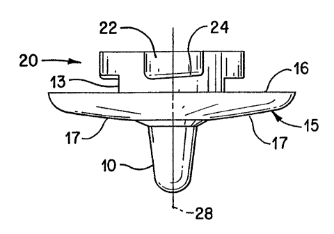
FIG. 1 is a side view of a cleat according to one embodiment of the invention.
FIG. 2 is a top view of the cleat of FIG. 1, showing the shape of the lobes to
be
inserted into a mated receptacle in the bottom of athletic footwear.
FIG. 3 is another side view of the cleat of FIG. 1.
FIG. 4 is a bottom view of the cleat of FIG. 1.
FIG. 5 is a bottom view of a receptacle that may receive the FIG. 1 cleat.
FIG. 6 is a top section view of the FIG. 5 receptacle wherein the top layer of
the
receptacle has been removed.
FIG. 7 is a side vertical section of the receptacle of FIG. 6.
FIG. 8 is a top view of the FIG. 6 receptacle wherein the top layer has not
been
removed.
FIG. 9A is a perspective right side view of a cleat according to a preferred
embodiment of the invention.
FIG. 9B is a perspective top view of the FIG. 9A cleat.
FIG. 9C is a perspective front view of the FIG. 9A cleat.
FIG. 9D is a perspective left view of the FIG. 9A cleat.
FIG. 10 is a top view of the cleat of FIG. 9A, showing the shape of the lobes
to be
inserted into a mated receptacle in the bottom of athletic footwear.
' FIG. I I is another side view of the cleat of FIG. 9A.
FIG. I2A is a top section view of a the receptacle for receiving the cleat of
FIG. 9A,
wherein the top layer of the receptacle has been removed.
CA 02240583 1998-06-15
WO 97/25890 PCT/US97/00481
-6-
FIG. 12B is a perspective bottom view of the FIG. 12A receptacle.
FIG. 13 is a side vertical section of the receptacle of FIG. 12A.
FIG. 14 is a bottom view of a cover for the FIG. 12A receptacle.
FIG. 15 is a side view of FIG. 14 cover.
FIG. 16 is a partial view of a FIG. 9A cleat inserted into a FIG. 12A
receptacle.
FIG. 17 is a bottom view of the FIG. 9A cleat.
FIG. 18 is a top view of an unassembled receptacle for receiving the FIG. 9A
cleat.
FIG. 19 is a bottom view of the FIG. 18 receptacle.
FIG. 20 is a section view of the FIG. 18 receptacle.
Description of a Preferred
Embodiment of The Invention
The invention comprises a system for allowing the quick attachment and release
of a
wide variety of traction gear. FIG. 1 shows that in one embodiment of the
invention, the
attachment system would be used to attach cleats, such as those disclosed in
U.S. Pat. No.
4,723,366, to the underside of athletic footwear. a cleat installed in the
bottom of a shoe using
the present invention, when viewed from the bottom, has a similar appearance
to the preferred
embodiment of the invention disclosed herein. Evident in FIG. 1 are the bottom
side 17 and
top side 16 of the plastic skirt 15, the ground-engaging head portion 10 of
the cleat, a base 13
to which the plastic skirt and ground-engaging portion are attached and a
retaining member
20, which in this case is a base 13 with three rounded extensions 22, all of
which are
positioned around a central axis 28. In a preferred embodiment of the
invention, the top I6 of
the skirt IS is slightly concave, and the bottom 17 of the skirt 15 is
somewhat convex.
FIG. 2 shows the topside 16 of the cleat skirt 15 and the retaining member 20,
which
has a roughly triangular shape with indentations 26. The extensions 22 of the
retaining
member 20 are used in conjunction with components inside the receptacle, shown
as item 30
in FIG. 5, for locking in place a properly inserted retaining member 20.
Locking in place
occurs after inserting the retaining member 20 into a mated receptacle opening
40 as shown in
SIG. 5 and FIG_ 6, and torquing the retaining member. The extensions 22 are
attached to the
base 13 (shown in FIG. 1 ), and together the extensions and the base form the
retaining
member 20. In a preferred embodiment of the invention, a completed cleat,
comprising the
CA 02240583 1998-06-15
WO 97/25890 PCT/LTS97/0048I
_7_
retaining member 20 and traction gear, is made out of plastic with a metal
core used to
reinforce the structure. Although the invention could be made entirely out of
metal, it is
preferable that the cleat be made partially of plastic and partially of metal.
When the retaining
member is plastic, the retaining member may be integrally formed with a
plastic skirt of a golf
cleat with a core, preferably metal, extending through the retaining member
and the traction
gear to form the ground-engaging head portion 10 shown in FIG. I.
In a preferred embodiment of the invention, upon insertion of the retaining
member 20
into a receptacle, the angled surface 24 (shown in FIG. 1 ) of the extensions
22 allows for a
tighter fit of the retaining member 20 into the receptacle 40 (shown in FIG.
5). The tight
connection not only serves to give a stable connection between the shoe and
traction gear, but
also serves to keep moisture and debris out of the attachment system.
FIG. 3 is another view showing the structure and proportion of the retaining
member
as attached to traction gear 21. FIGS. 2 and 3 show that in a preferred
embodiment of the
invention, the extensions 22 form a broad retaining member 20, and the base 13
is cylindrical
I5 and concentrically disposed around the center axis 28; the base 13 is
attached to the
extensions 22 and the traction gear 21.
FIG. 4, a bottom view of the FIG. I cleat, shows that, in a preferred
embodiment of
the invention, cleats do not have to be redesigned beyond modifying the
retaining member 20
(shown in FIG. I), and that conventional cleat designs are intended to be used
in conjunction
20 with the new retaining member; once a cleat is installed, the change in the
retaining system is
not apparent. A standard golf cleat wrench may be used to engage the traction
gear through
use of the wrench holes 18.
FIG. 5 is a bottom view of a receptacle 30 that may receive the FIG. I cleat,
showing
the receptacle opening 40, with indentations 44 along its perimeter for
accepting the retaining
member extensions 22 (shown in FIG. i ). FIG. 5 also shows the ledges 46 that
while serving
to form the shape of the opening 40, also serve to hold the extensions 22
within the
receptacle. Although preferred embodiments of the invention include a single
receptacle
opening 40, alternate embodiments of the system could have a receptacle with
separate
openings for receiving extensions.
FIG. 6 is a section view of FIG. 5 where the top layer of the receptacle has
been
removed to show the inner-cavity structure for receiving the retaining member
20 (shown in
CA 02240583 1998-06-15
WO 97/25890 PCT/US97/00481
_g_
FIG. 1 ). Within the cavity, formed by wall portion 50, there are several
cantilevered fingers
51, or spring arms, that are designed to grip and hold an installed retaining
member. When a
retaining member is inserted into the indentations 44 and twisted, the
twisting action causes a
protruding edge of an extension 22 (shown in FIG. 1 ) to push into and bend
the finger 51 to
allow the extension to be turned past the location of the finger. Once the
protruding edge of
an extension passes the location of the finger, the finger springs back to
nearly its original
shape, so that surface 53 rests against the perimeter of the extension 22.
This allows the cleat
to be removed, but only by exerting sufficient force to bend the finger 51
away from the
surface of the extension 22, an arrangement requiring much greater torque than
that required
during installation of the retaining member. In one embodiment, the fingers
are elongated in
shape, with surface 53 forming a curved tip to the finger. FIG. 6 also shows
bumps ~5 which
serve as a means for preventing a retaining member from being turned too far.
In a preferred
embodiment, the cleat should not be turned more than about 60°.
Coincident with the fingers
51 locking into place, the protruding edge of an extension is blocked from
further movement
by the bumps 55, and the entire retaining system is prevented from falling out
of the
receptacle by ledges 46. FIG. 6 also shows one method of attaching the
receptacle to the
underside of footwear by the use of mounting holes 57.
Spacing within the receptacle may be designed such that during installation of
a cleat,
the cavity 40 in which the extension is turned gradually narrows to compress
and securely
hold the cleat in place. Preferably the spacing is consistent or more gradual
than the angled
surface, so that the angled surfaces 24 (shown in FIG. 1) of the extension 22
being pressed
against the ledges 46 cause the fit to be tight. In addition, having three
extensions parallel to
the cleat skirt makes for a more secure base for a cleat.
FIG. 7 is a vertical section of a portion of the embodiment of the receptacle
of FIG. 6.
This view shows the ledge 46 formed by the bottom layer 45 of the receptacle
and the wall
portion 50 that defines the cavity within the receptacle. This view also shows
the slight rise
48 which forms a lip at the receptacle opening so that the edge of an
installed cleat's skirt may
overlay the Iip. The lip helps hold the cleat in place and makes it more
resistant to lateral
forces while the cleat is in use.
- FIG. 8, which is the FIG. 6 receptacle where the top layer has not been
removed, is a
view from the top of the receptacle 30 in accordance with a preferred
embodiment of the
CA 02240583 1998-06-15
WO 97/25890 PCT/LTS9710048I
-9-
invention. This view shows the top side 67 of the mounting holes for attaching
the receptacle.
FIGS. 9A-9D, 10 and 11 show a preferred embodiment of a cleat having the same
basic characteristics and structural concerns of the FIGS l, 2, and 3
embodiments discussed
hereinabove. Evident in FIG. 9A are the bottom side I7b and top side 16b of
the plastic skirt
ISb, the ground-engaging head portion 10b of the cleat, a base 13b to which
the plastic skirt
and ground-engaging portion are attached and a retaining member 20b, which in
this case is a
base 13b with three rounded extensions 22b, the extensions having an angled
surface 24b and
being positioned around a central axis 28b. FIGS. 9B-9D are respectively the
perspective top,
front, and left view of the FIG. 9A cleat.
Evident in FIG. IO are the corresponding topside 16b of the cleat skirt 15b
and the
retaining member 20b, with indentations 26b. The extensions 22b of the
retaining member
20b are used in conjunction with components inside the receptacle 84 of FIG.
12A, for
locking in place a properly inserted retaining member 20b. Locking in place
occurs after
inserting the retaining member 20b into a mated receptacle opening 40b shown
in FIG. 12A,
and torquing the retaining member. As with the FIG. 1 embodiment, upon
inserting the
retaining member 20b into a receptacle 84, the angled surface 24b (shown in
FIG. 9A) of the
extensions 22b forces a gradual compression of the retaining member 20b as it
is inserted
into the receptacle cavity 40b, resulting in a tight connection giving
stability while also
serving to keep moisture and debris out of the attachment system.
Also evident in the FIG. 10 embodiment is a modification to the FIG. 2
embodiment,
where the extensions 22 of FIG. 2 are modified to include an indentation 70
that further
enhances the invention's resistivity to unlocking and its unintentional
removal through
normal use. Increased resistivity is effected by an interlocking of a
cantilevered finger 74
(shown in FIG. 16} with the indentation 70. The cantilevered finger 74
corresponds to the
cantilevered finger 51 of the FIG. b embodiment, in which the cantilevered
finger 51 has been
thickened to afford a greater resistivity to unintentional unlocking. Further,
upon complete
insertion of the retaining member 20b into an appropriate receptacle 84 (shown
in FIG. 12A),
the end portion 90 of the cantilevered finger 74 rests within the indentation
70. Consequently,
removal of the cleat requires greater torque than that required to install the
cleat.
FIG. 11 is another view showing the structure and proportion of the retaining
member
20b as attached to traction gear 21b, indicating the location of indentation
70, as well as
CA 02240583 1998-06-15
WO 97/25890 PCT/US97100481
-10-
showing that the placement of the retaining member 20b and base 13b is
concentrically
disposed around the center axis 28b.
FIG. 12A is a section view of a preferred embodiment of a receptacle for
receiving the
cleat of FIGS. 9A-9D, IO and 1 l, where the top Iayer of the receptacle 84 has
been removed
to show the inner-cavity structure for receiving the retaining member 20b
(shown in FIG.
9A). FIG. 12B shows a perspective view of the FIG. 12A receptacle. As with the
FIG. 6
embodiment, included within the cavity, formed by wall portion 78, are several
cantilevered
fingers 74 designed to grip and hold an installed retaining member 20b. When a
retaining
member is inserted and twisted, the twisting action causes a protruding edge
of an extension
22b to push into and bend the finger 74 to allow the extension to be turned
past the location
of the finger. Once the protruding edge of an extension passes the location of
the finger 74,
the finger springs back to nearly its original shape, so that surface 90
contacts the perimeter of
the extension 22b. As described hereinabove, when the surface 90 contacts
extension 22b,
there is an interlocking of cantilevered finger 74 with the indentation 70
(shown in FIG. 10).
This allows the cleat to be removed, but only by exerting sufficient force to
disengage and
bend finger 74 away from indentation 70 and the surface of the extension 22b,
an
arrangement requiring much greater torque than that required during
installation of the
retaining member. As with the FIG. b embodiment, the fingers are preferably
elongated in
shape, surface 90 forms a curved tip to the finger, and bumps SSb serve as a
means for
preventing a retaining member from being turned too far during insertion.
Also evident in the FIG. 12A receptacle is another preferred embodiment for
attaching
the receptacle 84 to the underside of footwear by the use of a mounting slot
80. In this
embodiment, the perimeter 100 of the receptacle 84 comprises three flanges
disposed around
the receptacle opening 40b. In preferred embodiments, within each flange 82 of
the perimeter
are two slots 80 for mounting the receptacle 84 to footwear. Mounting of the
receptacle is by
methods known in the prior art, and may include forming sole material around
the slots, or
inserting a pin or other object through the slot to effectively nail the
receptacle to an inner-
sole of a shoe, and then forming the outer-sole material around the receptacle
so affixed. The
slots 80 are separated by a pre-determined distance and are preferably curved
to conform to
the curvature of the flange 82 in which the slot 80 is set. Also shown are
three openings 88 to
allow for attaching a receptacle cover 96 (shown in FIG. 14) to the receptacle
84.
CA 02240583 1998-06-15
WO 97/25890 PCT/LTS97/00481
-11-
FIG. 13 is a vertical section of a portion of the embodiment of the receptacle
of FIG.
12A. The FIG. 13 embodiment has a ridge 76 has been added in the bottom layer
86 of the
' wall portion 78 of the receptacle. In this preferred embodiment, the ridge
76 is located upon
the downward side of the receptacle and helps assure mold seal-off. Sealing
off the mold
helps prevent sole material from the outsole molding process from accidentally
spilling in
over the bottom-end of the receptacle during production. (The receptacle and
outsole are
preferably molded ground-side up.) In addition, by adding ridge 76 to the
basic design of FIG.
6, the structure of the FIG. 6 receptacle is strengthened, making it less
susceptible to torques,
distortions, or other forces. This results in better retention of the
receptacle within the sole of
athletic footwear.
FIG. I4 shows a receptacle cover 96 having three holes 92 corresponding to the
three
openings 88 shown in FIG i 2. In preferred embodiments, the receptacle cover
is designed to
attach to and seal the top end of the receptacle 84 of FIG. 12A, so that
during molding of a
shoe sole around the receptacle, the sole material does not seep under the top
edge of the
IS receptacle and fill its cavity. In addition, at the center of the cover 96
is a dome 94. This dome
hangs downward from the top of the receptacle, into the receptacle cavity for
receiving a
retaining member 20b (shown in FIG. 9A).
FIG. 15 shows a side view of the FIG. 14 cover, indicating the extent of the
dome 94
with respect to the rest of the cover's 96 proportions. The dome forms a
cavity 98 between a
sole of a shoe and the top of the receptacle 84 (shown in FIG. 12A). In
preferred
embodiments, during manufacture of a shoe sole, in addition to sole material
being molded
around the receptacles, sole material is also allowed to fill in the cavity
98. Consequently, as a
retaining member 20b (shown in FIG. 9A) is inserted into a proper receptacle,
the insertion
forces a compression of the dome which in turn compresses the sole material
filling the dome.
The dome 94 serves two purposes. First, when the .retaining member 20b of
traction gear is
fully installed within a receptacle 84 (shown in FIG. 12A), the compression of
the dome
results in a downward pressure upon the extensions 22b from the dome trying to
re-expand
into its original shape. Second, when one tries to remove the traction gear
from the receptacle
84, the re-expansion of the sole material helps push the retaining member away
from the sole,
thus aiding in the removal of attached gear.
In preferred embodiments, the extensions for the attachment system are molded
using
CA 02240583 1998-06-15
WO 97/25890 PCT/US97l00481
-12-
conventional molding processes. Preferably, the molding process uses mold
components
having expandable cavities, these cavities allowing for undercuts to be molded
without the
use of side actions or slides. The receptacle may be molded using conventional
molding
processes, where the receptacles are preferably produced on a horizontal or
vertical press and,
with the aid of precision mold design and building, are formed in a manner
well-known in the
art.
In preferred embodiments of the invention, during manufacture, the receptacle
portion
with the top cover attached is placed in an outsole mold, and the ground
surface part of a shoe
is then molded. The molding process is preferably one of injection or
compression molding.
The particular location of each receptacle within the mold depends on the
intended use of the
shoe and the design of the shoe's shape. During manufacture of the outsole of
one
embodiment of the invention, mold support-braces may be used to help ensure no
deformation of the receptacles during the molding of the sole. Preferably, the
support-braces
are negatives of the receptacle's shape such that when a brace is inserted
into a receptacle, the
receptacle 84 and pin holes 88 (shown in FIG. 12A) are temporarily sealed off
to prevent sole
material from filling in the receptacle cavity 40b and pin holes 88. These
pins may also be
used to help orient and position the receptacle so that sole material flows up
to and not
beyond the ridge 76 (shown in FIG. 13} that is visible on the ground side of
the receptacle.
Once the outsole is molded, a second material may be molded or cemented to the
outsole, and
also cemented to the upper portion of the shoe. In this embodiment, the
outsole and second
material combination form a completed sole having the embedded receptacles.
In some embodiments, the shoe sole may be formed of light-weight materials
such as
EVA or foam. In such embodiments, the sole material may be insufficiently
strong to hold a
receptacle firmly in place. Consequently, in preferred embodiments, a support
plate may be
added to the sole structure, wherein the receptacles_are attached to the plate
at the desired
locations, and the sole is formed around the attached receptacles. Such plates
may also be
used for heel support for footwear having light-weight heels; similarly, for
heel-plates,
support-pins may also be used to help prevent heel receptacle deformation.
FIG. 16 is a partial view of a FIG. 9A cleat inserted into a FIG. 12A
receptacle.
Shown is a magnified view of the tip 90 of a cantilevered finger 74 at rest in
indentation 70 of
retaining member 20b. As described hereinabove, after installation of a cleat
into a receptacle,
CA 02240583 1998-06-15
WO 97/25890 PCT/CTS97/00481
-13-
the torque required to dislodge the cantilevered finger 74 from the
indentation 70 is much
greater than that required during installation.
FIG. 17, a bottom view of the FIG. 9A cleat, shows that in this embodiment of
the
invention, a three-pronged wrench is inserted into the three wrench holes 110
used to remove
the cleat. Use of a three-wrench-hole design gives greater stability during
insertion and
removal of a cleat, and allows greater torque to be applied, without slipping
out of the holes,
during such insertion and removal.
FIG. 18 is a top view of an alternate embodiment where a modified FIG. 14
cover is
attached to the FIG. 12A receptacle through a flexible attachment region 120.
In this
embodiment, the receptacle 84 and cover 96 may be integrally formed of a
single portion of
production material, and simultaneously formed from a single mold. Before
insertion of this
embodiment of the receptacle into a shoe sole, the cover is flipped closed to
cover the top of
the receptacle. The FIG. 14 cover is modified to include two cover flanges 122
which, when
the cover is closed, rest in-between two of the receptacle flanges 82. The
cover flanges 122
also have slots 124, which in addition to the receptacle slots 80 described
hereinabove, are
used for mounting the FIG. 18 combined receptacle and cover to the underside
of footwear.
FIG. 19 is a bottom view of the FIG. 18 embodiment, showing the ridge 76 (see
FIG.
13 hereinabove) which helps prevent sole material from the outsole molding
process from
accidentally spilling in over the bottom-end of the receptacle opening 40b
with attached FIG.
14 cover having the features as disclosed hereinabove for FIG. 12A and FIG.
14.
FIG. 20 is a top section view of FIG. 18, showing the relationship between the
extent
of the dome 94 and the receptacle 84. Also shown is the region defined by
portions 126, 128
for receiving the cover flange I22 when the cover is closed over the
receptacle 84.
The above description of the drawings provides details of several embodiments
of the
present invention. It is of course apparent that the present invention is not
limited to the
detailed description set forth above. Various changes and modifications of
this invention as
described will be apparent to those skilled in the art without departing from
the spirit and
scope of this invention as defined in the following claims.