Note: Descriptions are shown in the official language in which they were submitted.
~ CA 02240664 1998-06-15
W O 97123772 PCT~US96/20015
STRUCTURAL MONITORING SENSOR SYSTEM
BACKGROIJND OF THl~ INVENTION
~ The present invention is directed to a system for continuous physical h~e~lity
monitoring of large civil structures such as bridges and high-rise bl~ikling~ ...whe-eill the
relevant sensor data stream is generated continuously and tr~n~mitt~l to the data ga~h~ g
S location without the need for an incoming triggering signal of any Icind; i.e., it is a one way
lln~ iion system. Specifically, it is a concept for an h,lt;-li.lked multi-parameter Early
Warning Sensor system with a full time data n,and~e",ent capability for structures. The
invention is also directed to both the system construction, with its co.~ C~iOn capability,
and also unique designs of specific sensors applicable to the system as a whole. As a
10 practical example of application of the present invention to a structure, the description in this
application is directed primarily towards system applications for bridge in~egll~y early
warning systems. However, it should be understood that the system and its benefits may be
applied to a wide range of physical structures.
The system of the present invention, as applied to bridges, is unique in its ability to
15 address the four principal failure mecl~ ...c or precursors to failure most col~ ollly
associated with bridges. These are:
1. Catastrophic failure where some major structural defect prc,g.esses lm~letected to the point
where some critical section of the bridge collapses. This will be ~lesigned Slow Movement
Failure .
20 2. Vibration-associated Failure where sporadic traffic loading creates a vibration envirolll"ent
which can accelerate failure, such as fatigue, and also be a ~ gnostic tool useful in pre licting
failure. This is ~le~i~n~t~d Rapid Movement Failure.
3. Corrosion-induced ~ailure where the steady winter applications of salt eventually pe,llle~le
the concrete to the depth of the rebars which begin to corrode. This weakens the rebars and
25 also causes the concrete to spall off the bars. It also weakens the concrete. This is
d~ign~tecl C~orrosion Failure.
~ 4. Low temperature--n-luced failure where a freezing road bed can lead to frost formation
and result~nt pot-hole development. Pot-holes can exaggerate the stress on the entire bridge
CA 02240664 1998-06-15
W O 97/23772 PCT~US96/20015
structure through vehicular impact. This is decign~t.od Temperature Related Failure, and it
is addressed through Te""~e,alu~e Sensing and Pot-Hole Sensing.
The present invention e.lco...r~e~es to major aspect of novelty. The first aspect is a
harness which is att~hed ~ ly to a structure. This harness permits an array of
S interco~nloct~d tr~n~dncers to be deployed at specific sites on the structure for specific
sensing applications. It also provides the sensors with a common electro-optic interface
which may be linked with a remote co,lllllui~ication system ...by a one-way data tr~n~mi~sion
system which does not require an incollling signal stimulus to trigger the sensor data
download.
The second aspect relates to various types of the sensors which may be ~tt~ P~l to this
harness. Both analog and digital sensor types are described, and specific embo-1im~nt~ for
corrosion mo~ o.il-g, pothole monilo,;ng, vibration monilo~ g and lelllpel~lure monilo~ g
are included in the present disclosure, as well as traffic flow, scour, bridge deck deflection,
cross-wind velocity, lelllp~lalul~, fire, etc.
BRIEF DESCRIPTION OF THE DRAWINGS
FlG. 1 is a diaglal""~aLic general view of an optical ~--oniloling system to which the
present invention is applied;
FIG. 2 is a diag.a.nl--dlic view of a portion of the optical monilo,iilg systemwhich
includes a feature of the present invention for d~lerl"ining dil~e~;lion of mùve~enl,
FIG. 3 is a dia~ lllllalic view of a conventional encoder pattern for an optical sensor
which forms part of the optical ~-loniluliilg system;
FIG. 4 is a chart si~wing relative displ~c~m~ont of the reticle and mask elementc which
form part of the optical sensor, plotted against reflected light ~"l~nsily for the sensor encoder
pattern of FIG. 3;
FlG. S is a chart showing the ~ligiti7ing of the reflected light signals of the chart of
PIG. 4;
FIG. 6 is diag,i.. ~l~c view of a first embodiment of a encoder grid geometry for
the reticle and mask of the optical sensor ûf the present invention;
FIG. 7 is a chart showing relative displ~em~nt of the grid elements of the optical
30 sensor plotted against reflected light for the encoder pattern of FIG. 6;
CA 02240664 1998-06-15
WO 97/23772 PCT~US96/20015
FIG. 8 is a chart showing the ~1igiti7inf~ of the reflected light signals of the chart of
FIG. 7;
FI~S. 9 and 10 are diagr~l-llllatic views of an encoder pattern for the reticle and mask
elemto,nt.~ of the optical sensor of the present invention, showing a modification for dPtec~ing
S direction of relative movelllelll of the reticle and mask by means of quadrature. FIG. 9 is
the mask and FIG. 10 is the reticle with two tracks having the quadrature 90~ offset;
F~S. 11 and ~3 are dia~ tic views of a further modified encoder pattern for
reticle and mask of the optical sensor of the present invention;
FEGS. f2 and 14 are charts showing the optical power pattern res~lting from the
10 relative ~i~pl~ce,ment of the reticle and mask of the optical sensor plotted against reflected
light hl~llsily for the encoder pattern of FIGS. l l and 13, respectively; and
FIG. 15-17 are diagli.. ,.liG views of a further re*nem~-,nt of the modified encoder
paLltll~S of FIGS. 11 and 13 which pertnits deliberate alteration of the optical power patterns
of FIGS. 12 and 14.
FIG. 18 is chart showing the relative displ~ceme,nt of the reticle and mask of the
erine...~ of the modifie~l encoder patterns of FIGS. 15-17;
FIG. 19 is a front elevational view of a tensioner/sensor assembly for moni~oling a
structure;
FIG. l9A is a diagr~mm~tic view of the sensor portion of the tensioner/sensor
assembly of PIG. 19;
FIG. 20 is diagl~ lllalic view of a sensor as applied to a bridge for Illo~ oling
deflection;
FIG. 20A is an enlarged view;
FIG. 21 is a diagl~ ic view illu~llalil~g a col,lbind~ioll deck deflection and pier
tilt monilolillg system with the use of sensors;
FIG. 22 is a diagrammatic view illu~ ting a sensor system for d~tPcting scour at the
base of a bridge pier;
FlGS. 22A and 22B are diagrammatic illustrations of a tilt meter employing the
principles of the present invention;
FIG. 23 is a diagl,.".",~lic view of a modified Illonilo.i,lg system for (l~otecting scour
at the pier portion of a bridge;
CA 02240664 1998-06-15
W O 97/23772 PCTAJS96/20015
FlG. 24 is a diagrammatic view of an application of the monitoring system of thepresent invention for moni~ i,lg bridge ~ pel~ufe;
FIG. 25 is a diagrammatic view of a moniloli,~g system of the present invention for
molliLo,i,lg wind velocity;
5FIG. 26 is a diagl~........ AI;c view of a monilolillg system of the present invention for
~l~tecting potholes in the deck portion of a bridge;
FIG. 27 is a graph illusl~ lg the application of the pothole detection system of FIG.
26 for dele- .llillil~g a repair threshold value;
FIG. 27A is a diagrammatic view of a modified application of the pothole detection
10 system of FIG. 26;
FIG. 27B is a flow chart of the pothole sensing algoliLIl"l for the pothole mo.~iloling
systems of FIGS. 26 and 27A;
FIG. 28 is a diagrammatic illustration of the corrosion sequence of a rebar for
monhoring corrosion in concfeLe which expands over time;
FIG. 29 is a graph showing the corrosion over time seqllen~e of the rebar of FIG. 28;
FIG. 30 is a diag,i........ ~lic view of a corrosion sequence for a rebar for monitoring
corrosion in concrete which shortens over time;
FIG. 31 is a graph illu~ ing the corrosion over time sequence of the rebar of PIG.
30;
FIGS. 32 and 33 is a dia~ l""lalic view of the first enviroml~ l of a corrosion
moniL,Iillg sensor for con~ e employing rebars which shrink over time;
FIGS. 34 and 35 are diagla~ ;c views of a second modification of a corrosion
sensor for concrete having rebars which shrink over time;
FIGS. 36-39 are dia~ G views of â third modification of a corrosion moniloLi,lg
sensor for col clc;le using rebars which shrink over time;
FIGS. 40 and 41 are dia~ ;c view of appalaLus for mon,l~ g the surface
hard,less of concrete over time;
FlG. 42 is a top plan view of the reflective grid portion of a fatigue fuse embodying
the principles of the present invention;
FIG. 43 is a top plan view of the ll~n~ ive mask portion of a fatigue fuse of the
present invention;
CA 02240664 1998-06-15
WO 97/23772 PCT~US96/20015
F~IG. 44 is a top plan view of the reflective grid and ~ ive mask portions of
PIGS. 42 and 43;
~IG. 45 is a side elevational view of a fatigue fuse of FIG. 44 shown applied to a
structure to be monitored;
FIG. 46 is a chart showing testing results for the fuse of FIGS. 44 and 45;
FIG. 47 is a diag~ tic view of the monilo,i,lg system of the present invention as
applied to monilo~ g t~lllpela~ule; and
PIG. 48 is diagl~",lllalic view of a modification of the monilo~ g system of thepresent invention for mol.i~clh~g ~ el~ure.
DETAILED DESCRIPTION O~ THE INVENTION
OPTICAL MONITORING SYST~M
The optica1 structural integrity moniLorillg system of the present invention includes a
sensor interrogation harness which exploits a simple sensor dirrerellliaLion technique known
as Time Division Multi~plexing, TDM. Since light travels through an optical fiber at a fixed
velocity, each sensor is ~ checl to the pulsed laser source by a difreLGIll length of fiber.
Further, by also causing the sensors' output to be reflected back down the same fiber to the
photo-~lec~or, the di~re~ idl delay is precisely doubled.
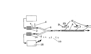
Refernng first to PIG. 1, the optical monitoring system of the present invention is
generally inrli-~t.~d by the ~ e.lce numeral 3 and includes a 1aser 2 which is capable of
genela~ing pulses of light 4 into one leg 7 of a Y-coupler 6. The other leg of the coupler i
co.-i-e~ d to a photo detector 14 which, in turn, is OpelaLivt;ly conn~oct~d to Cil'~;uilly 18. A
cabled bundle of optical fibers 8, is col-necl~d to the Y-coupler 6. A single optical fiber from
the cable 8 is connected to each of a plurality of optical sensors 12 located at strategic
locations on the structure which is being monitored, in those i-.~l;.i-ces where the direction
of motion of the sensor is unambiguous. Each sensor has an 'on', or reflecting condition and
an 'off', or non-reflec~ing condition, to be described. Each light pulse from the laser 12
proceeds to the cables 20 and 22 via the coupler 6 to each of the sensors in the system. If
a sensor is in its reflective condition, some tangible portion 10 of the light pulse will travel
back down the same optical fiber and pass l~llough the Y-coupler 6 and on to the photo
detector 14 via the cable 9.
CA 02240664 1998-06-15
WO 97/23772 PCT~US96/20015
The cilcui~l~y 18, of the photo-detector is programmed to clock the arrival, or non-
arrival depending on the sensor's condition, in certain time windows. These arc known and
programmed into the co,l,l,ulel which will ~ role know which sensor is responding in
whatever mode, reflective (logical one), or non-reflective (logical zero). Because the laser
5 2 is pulsing at a frequency of up to half a mil1ion cycles per second, 0.5 MHZ, there is
ample oppo,~unily to capture the change from cl~tec~;.hle signal to non-detect~hle without
missing a step in the sequence.
Each optical sensor 12 is mounted on the structure to be monitored to detect there1ative movement of a first elem~nt of the structure relative to a second element of the
10 structure along a first axis. Each sensor co~llprises a probe 21 which is slidably mounted
within a housing 23. The probe c.~ a l~ s~i~re grid7 or reticle. The housing
contains a reflective grid, or mask. The reticle moves longitu(lin~lly re1ative to the mask as
the probe moves relative to the housing. An optical fiber from the fiber optic cable extends
into the holl~ing so that the end of the optical fiber is at the reticle for Ll~n~u.i~ a pu1se
15 of light at a right angle to the reticle. Light passing llllou~ll the tran~ ive areas of the
reticle is reflected by the mask back to the end of the optical fiber. Such a sensor is known
as a reflective optical sensor. The present invention is also applicable to a tr~n~mi~ive
optical sensor which is similar to a reflective optical sensor except that the reflective areas
of the mask are L~ ive areas. Light from the optical fiber passes through the
20 ll~n~ ve areas of the reticle and mask and strikes the end of a second optical fiber at the
opposite side of the housing for tr~n~mi~ion to the Y coupler. The probe is fixed to a first
çlem(~.nt of the structure to be nlonilol-ed. The housing is fixed to the second element of the
structure to be monitored.
The reticle and mask are located in s~al~le spaced parallel planes. The mask is
25 mounted in the encoder for movement relative to the reticle in accor~lce with the relative
movement between the first and second elements of the structure to be monitored. The mask
and the reticle function as an encoder for the light pulses received from the laser and reflected
to the photo-de~e~lor 14. The reticle has a plurality of evenly spaced light impervious
surfaces. The areas between the light impervious surfaces are pervious to light. The
30 pervious areas are the active areas of the reticle and the light impervious areas are the passive
areas of the reticle. The mask has a plurality of evenly spaced ul~~rollll reflective surfaces
CA 02240664 1998-06-15
W O 97/23772 PCT~US96/20015
.
which are considered the active areas of the mask. The areas between the reflective surfaces
are non-reflective and are considered the passive areas of the mask.
FIG. 2 shows a detail of the basic interrogation harness of PIG. 1 having to do with
- "quadrature", which allows the detection cir~ y to be able to dG~GIll~ e the direction of
5 relative movement of the elements of the structure which are being monitored. The cable or
bundle of optical fibers connectecl to the coupler 6 are divided into two groups of optical
fibers, indi~ted by the reference nume~als 20 and 22. A single optical fiber from each of
the groups 20 and 22 is connecte~ to each sensor 12 at various strategic locations along the
structure to be monitored. A shown in FIG. 2, a single optical fiber 20a from the bundle of
fibers 20 is conn~cted to sensor 12a and a single fiber 22a from the bundle of optical fibers
22 is con~-toc~ecl to sensor 12a. A single optical fiber 20b from the bundle of optical fibers
20 is connPcted to sensor 12b and a single optical fiber 22b from the optical fiber bundle 22
is colme.;led to sensor 12b. The bundle of fibers, or cable 22 is configured to include an
extra length, inAir~tecl by the Ic~erGnce numeral 25, i~ y adjacent the Y-coupler 6.
This enables any sensor in the system which re~uires a dual fiber quadrature feature may have
a fiber selected, one from each of the two cables 20 and 22, at a specific physical location.
The ~uadrature feature is described in greater detail heleinbelow in connection with PIGS.
9 and 10. The cables are sufficiently dirfGIGIll in length so that their respective output pulses
will be distinguishable via a T~M protocol.
The encoder geol,,GIIy of the reticle and mask of conventional sensors employ equal
active amd passive areas for the reticle and mask patterns as shown in FIG. 3, wll~ .eill each
pattern, generally indicated by the reference numeral 16, has a plurality of active areas 15
which ~lt(~ t~ with a plurality of passive areas 17. The result of employing two equal
patterns, each having an equal active area to passive area ratio, creates a saw-tooth pattern
output as shown in FIG. 4. In many structural applications, it is hll~olL~-L to be able to
monitor small relative move",el,L~ between two structural ele.llel,~. Therefore, it is desirable
to have this "off" intervals of the sensor equal the "on" intervals as closely as possible. The
problem is that it is neces~a,y to be able to locate the half-height intensity of the saw tooth
24, FIG. 4, if one is to divide the output into equal on and off intervals, see 26, FIG. 5.
This is normally accomplished by the technique of l-lea~ulhlg the full peak height 28, FIG.
4, and con-lucting the m~them~tics in the cilcuiLIy of the light detection logic circuit. In
CA 02240664 1998-06-15
W O 97/23772 PCTAUS96/20015
order to be able to power a multiplicity of difre~ el~l fiber-sensor systems from a single source
and detectin~ their outputs at a single d~tector, the present invention provides a low cost and
simple approach which accommodates widely varying power level from sensor to sensor.
The problems associated with conventional prior art sensors is overcome by the sensor
12 of the present invention. Each sensor 12 of the present invention in~hl~es a grid encoder
design which differs ~ulJ.~ lly from those of conventional sensors. A first embodiment
of applicant's encoder grid design is shown in FIG. 6, wh~rt;ill the pattern or geometry of
the reticle and the mask, generally indicated by the reference numeral 29, includes a plurality
of equally spaced uniform active areas 33. The areas between the active areas 33, indicated
10 by the reference numeral 31, are twice as wide as the passive areas 33 along the lon~ih~-lin~l
axis of the grid or the first axis. The active areas 33 of the reticle are the light pervious areas
and the active areas of the mask are the reflective areas. This mask geometry autom~ti~lly
causes the light output to blink on and off in equal proportions by the exre lient of keying
oM the b~çlin~ trigge~ g signal level 30, FIG. 7, rather than the sensor-specific mid-height
1~ peak inl~llsily. As shown in FIG. 7, the absolute peak height range 32, has little affect on
this new b~.o.line triggering protocol, as seen by the output signal 36, FIG. 8.Referring to ~IGS. 9 and 10, there is shown a first modified grid design of the present
invention, wherein the ll~nc...;~ion grid, or reticle, generally in~ ted by the reference
numeral 38, is iclentic~l to the grid design of FIG. 6, while the reilective grid, or mask,
20 generally indicated by the ler~;rel-ce numeral 40, has two identical portions, generally
indicated by the reference numerals 40a and 40b, as shown in PIG. 10. The reticle 38 has
active, or light pervious areas 35 and passive, or light im~e. ./ious areas 37. Each portion 40a
and 40b of the mask 40 has active, or reflective areas 39 and passive, or non-reflective areas
41. The non-reflective areas 41 are twice as wide as the reflective areas 39. The second
25 portion 40b is offset from the first portion 40a by half the ~licf~nce of the width of an active
area along the lonpitll-lin~l axis of the mask. In this embo~im~nt two optical fibers are
employed as shown in FIG. 2. One optical fiber is aligned with the portion 40a and the other
optical fiber is aligned with the portion 40b. Each optical fiber has an end surface which is
parallel to the plane of the mask 40 for dir~Lil~g a pulse of light transversely of the active
30 sur~aces of the reticle and the mask. Directionality of the relative movement between the
elements of the structure being monitored is resolved by quadrature as provided by the
-8-
CA 02240664 1998-06-15
W O 97/23772 PCT~US96/20015
Orr~ g of the offset portions 40a and 40b. The variability in light directiona1ity which is
encountered in actual practice may require slight modification in the 2:1 ratio to produce the
equal 'on' and 'off' condition.
- Referring to FIGS. 11-13, there is shown another modification of the encoder
S geometry of the present invention, generally in-lic~ted by the reference numeral 48. In the
sensor geometry 48, the reticle and the mask do not employ the same active area to passive
area ratios.
The sensor geometry 48 includes a tr~n~mi~ive grid, or reticle 42 and a reflective
grid, or mask 43. The reticle 42 has a plurality of uniformly spaced light impervious
surfaces 45 which are the passive areas of the reticle. The areas between the surfaces 45,
indiç~t~.cl by the ,erelellce numeral 47, are light pervious and are the active areas of the
reticle. The widths of the active and passive areas of the reticle 42 along the first, or central
longitlu1in~l axis of the sensor, is one-to-one. That is, the width of each light impervious
surface 45 is equal in width to each light pervious area 47 along the first axis. The mask 43
has a plurality of unifo~ , equally spaced reflective surfaces 49. The areas belweel~ the
reflective surfaces 49, indicated by the reference numeral 51, are non-reflective and repleselll
the passive areas of the mask 43. Reflective surfaces 49 l~resenl the active areas of the
reflective mask 43. The width of each passive area 51 is ~u~ y larger than the width
of each active area 49 along the first axis, or longitu~in~l axis of the sensor.I~ has been found that threshold triggering will yield an al~plo~ alion of the 1:1
digital ~wi~ ing with either 4:1 or 5:1 reticle:mask active area ratios, see FIGS. 11 and 13.
The corresponding signal threshold ~wilching outputs are depicted in FIGS. 12 and 14,
respectively. The lateral mask 43, motion relative to the fixed reticle 42, in FIG. 11 is shown
as a descending sequence of zeros and ones against the sequential Jlulllber on the right hand
side of FIG. 11. The reflective ratio in FIG. 11 is 4:1 and a 5:1 ratio is shown in FIG. 13.
The higher ratio will more closely approach the desired signal equality at threshold ~wilchillg,
but at the t~Ypçn~e of reflective active area and concolllil~ll reflected signal strength. It is
appalcllL from FIGS. 12 and 14 that the 'logical one' periods resnlting from threshold
triggering 44 are longer than the 'logical zero' periods 46, FIGS. 12 and 14.
This analysis was co~rlllcted under the as~ullll~lion that the reticle-impinging light is
orthogonal to the structure 48, FIG. 16. However, in actuality this is not the case. The light
~ CA 02240664 1998-06-1~ T ~ f~ I~
- 0~)5-723-201 5~G,~lS76/2vul~
S lo ~EC 199
will emerge from the optical fiber at a range of angles, typically up to 25 degrees or so to
the vertical 50, as shown in FIG. 16. This resu1ts in a decrease in the effective area of the
reflector patches, thus e~fective1y reducing the on cycle, and evening up the intervals between
"logical one" and "logical zero" for the desired threshold ~wilchillg protocol. This is
S illustrated as light rays 52, FIGS. 16 and 17 and ~-latlle.. ~lic~lly in FIG. 15. The precise
relationship for the anticipated signal shift and the angle of light impingement is also given
in FIG. 15.
Fig. 15 Illustrates a 1: I switching with an asymetrical mask whe.ein a = Mean Angle
of Incident Light and D=Distance from Reticle to mirror. When the reflective width W of
10 the mirror is infintely small, the threshold switching is 50:50.
Therefore, when the shadowed width, 'S' is equal to 0.5W, then the erreclive
reduction in W from both ends will have the effect of making 'W' infinitely small.
ThisoccurswhenS=D.tan(a)andW=2S, sothat: W=2D.tan(a)for 1:1 swilching.
Thus, the true ~alue of this approach is that a set threshold signal strength for
15 ~wilching can be established for a particular mask/reticle ratio, based on the system-imposed
variables of an optical fibers Numerical Aperture and the specifics of the detector system.
Once set, however, further variations in the specific fiber signal ~llengll- will not have any
effect on the switching ratios.
The change in the threshold signal level ~wilching is shown in FIG. 18, where the
20 original orthogonal light-derived signal 54 is nallowed to the dashed signal profile 56 so that
the threshold 'one' interval 58 is e~ual to the threshold 'zero' interval 60.
Referring to FIGS. 19 and 19A, there is shown a tensioner/sensor assembly, generally
indicated by the reference nurneral 62 for a drone cable 61. The assembly 62 includes an
optical sensor 12 and a fixed pulley 63 which is fixed rotatably mounted on an axle 72 which
is fixed to a mounting bracket 64 attached to a bridge deck or other structure to be
5 monitored. The housing portion 23 of the sensor is also mounted on the angle 72. The
probe portion 21 of the sensor 12 is rotatably mounted on an angle 73. One end of the axle
73 is fixed to a floating pulley 65. The other end of the axle 73 extends into a vertical slot
in the mounting bracket 64 for guiding the axle 73 as the floating pulley 65 moves toward
and away from the housing portion 23 of the sensor 12. The probe portion 21 of the optical
10 sensor 12 is fixed outwardly by an internal spring in the housing portion 23 of the sensor.
-10-
p~No~.D SHÉE~
CA 02240664 1998-06-15
W 097/23772 PCTrUS96/20015
The ~ulwdldly biasing sensor 12 is used in the examples of the present application.
However, in some applications of the invention, an inwardly biased sensor may be used or
a sensor which does not have a bias. The drone cable 61 is wrapped at least once around the
pulleys 63 and 65. An optical fiber 66 or fibers 66 extend from the optical fiber cable 67
5 which is deployed next to the drone cable 61.
- The floating pulley 65 is compelled by the internally-sprung encoder to move away
from the fixed pulley 63 to aCcommr~ te any slack in the drone cable 61.
Any such movement is registered by the digital mask in the encoder via the
hl~ell~lhlg optical fibers.
ln the event that larger cable length changes are anticipated than can be accommor1~t~d
by the travel of the encoder, multiple pulley sheaves can be employed to (l~.m~nify the
cable's travel. Any such adj~ ..e..l would be readily co~ )en~aled for in the co,ll~uler
software.
The optical sensor is plerel~ly enclosed in a protective box or the equivalent in order
15 to safeguard the sensor from el~viro~ pnt~l hazards.
The Encoder body is internal1y spring loaded to the m~xim~1m extPn~ion possible.Rer~llillg to FIG. l9A, certain movt;l"e~ in~ ce~l co",l)les~ e forces will overcome the
spring loading and cause the reticle Quadrature strip 68 to translate past the mask strip 69 and
the hllello~ ing optical fiber connector at point 71 whose entrained fiber will be emitting a
20 con~lll high bit-rate stream of pulses. This output will be reflected back into the same fiber
for the return trip to the detector so a10ng as the openings of the reticle strip 68 coincide
with the reflective strips of the mask strips 69.
DRONE CAI3LE SUPPORT SYSTEM
One of the prime realur. ~ of the distributed fiber cable sensor system has been its dual
25 function as both the conduit for the sensor con~-ctors and the actuator for sensor movement
via strategic sensor p1~cem~nt In some instances where extreme tii~t~n~es exist between the
two in~e~iogdlion anchors, in span deflection ~ u~ lent for example, there may be
problems of ~c~c~mn1~tP~ cable weight. Here, we are referring to the calellaly effect of a
cable stretched btilw~ll two mutually distant points. Any change in separation b~;;lw~n those
30 points should translate directly into an equivalent change in the interposed encoder sensor.
CA 02240664 1998-06-15
WO 97/23772 PCTrUS96/20015
When the fiber cab1e is deployed over long distances, there is the risk that the cables own
tendency to ca~enaly under its own weight will nullify its ability to react to the extrinsic
ting agent, in this example the downwald deflection of a bridge deck under load. The
obvious palliative is to create an overwhelming tensile stress on the cable through imposition
S of a ~I~assi~e expansion spring in the cable. However, a vicious circle is created where the
cable must be buLked up to survive these tensile forces which only makes the cable heavier
and more prone to sagging under its own weight, raising the pros~ecl of further strengthening
and concomitant weight increase. In order to avoid this circular problem, a scheme has been
derived which side-steps this problem.
10 THE DRONE CABLE SOLUTION
Many embodi...~.ls of the distributed cable system of the present invention employ
the fiber cable and drone cable for the monitored structural segment. The goal of this
improvement is to show that the basic principal of the system may be ~,~se, vt;d while adding
a series of application-specific distance-registering around fiber drone cables whose only
15 function is to accurately and swiftly follow the relevant di~t~nce ch~,-ges.
As shown in FIGS. 19 and l9A, ten~ioned drone cable is wrapped at least once
around the two pulley assemblage which COI.lp- ises the tensioner portion of the optical sensor.
The floating pulley is compelled by the internal spring of the sensor to move away from the
fixed pulley to accommodate any slack in the drone cables caused by movement of the
20 ".o.lilo-ed bridge section. Any such movement is legisleled by the digital mask in the sensor
via the interrogating optical fibers. This way, otherwise separately ~u~olled and deployed
optical fiber cable enjoys the ability to vicariously monitor the drone cable's m(J~elllt;lll
withlout the onus of having to sustain the inter-anchor span stresses. FIG. 21 shows the
system mo~ ing for bridge deck deflection. Here, the fiber cable monitors the drone
25 cable's movement due to the deflection of deck-att~ch~d deflectors, which exaggerate the
bridge deck motion and thus the drone cable motion, encoder translation, and optical signal
tr~ncmi~ion.
CA 02240664 I998-06-I5
W O 97/23772 PCT~U$96/20015
DECK DEr~LECTIO N AN D PI~R TILT M ONITORING
Referring to ~IGS. 20 and 20A, the bridge deck deflection and pier tilt monitoring
system of the present invention is generally i~-lie~te~l by the ~ e,ellce numeral 70. The
- system 70 includes an optical sensor 12 applied to the bridge deck 74 which is ~ull~o~Led
S between a pair of piers 76. The bridge dleck motion to be (letect~d is in-3ie~tPd by the arrows
75. A drone cable 78 is located below the bridge deck 74 and extends between the piers 76.
Drone cable deflectors 80 are fi~ced to the underside of the bridge deck 74 for ~ ini~
the drone cable 78 spaced from the underside of the bridge deck. The optical sensor 12 is
operatively connecte~ by the drone cable 78 and is supported from the underside of the bridge
deck 74 by one of the deflectors 80, see FIG. 20 in particular. An optical fiber cable 82 is
loose1y ~ul)pol led on the bridge deck 74 and is ~tt~he~ to the deflector 80. An optical fiber
84 is broken out from the fiber cable 82 and is operatively connect~l to the optical sensor.
The drone cable 78 is preferably made of an aramid fiber such as Kevlar~9. The advantage
of using aramid fiber cable as a censolulg colll~o~ nl is that it is very flexible but
15 inPYten~ihle and has virtually zero thermal expansion. Further, it is extremely strong and
hazard-l~si~ particularly when ~ht-~thecl by an ellvhon...~ ;.l1y-~)role~;Liv-e outer jacket,
and is also light in weight. Thus, it lends itself pel~ec~ly to depl.,y"lenl as a remote sensing
co,l,~onelll on bridges and large structures alike. This modification in no way detracts from
the origina1 ple,l,ise of the distributed structural monil~lillg system. lndeed, it extends the
application of it through the use of application-specific drone cables whose sole task is to
create the conditions for an otherwise til~virom~ l-isolated fiber cable to address in its
col,ven~iomal and intend~d fashion.
It wi11 permit the m~nilo,hlg of many fiber cable-h~us ~l~vilom~ by
deploying the appLopliate drone cables belweell the hazardous locations and the fiber cable-
benign sensing area. Obvious examples include high and low L~IIIPG1~lUI'e~ che,-,icals, nuclear
radiation, under water, and many more. Applications that use the drone cables include deck
deflection and pier til~ sensing, pier scour detection, pile movement Illo~ Ling, wind velocity
del~""in~lion, pothole detection and traffic monitoring, and building movement and fire
detection.
As shown in lFIGS 20 and 20A, the drone cable 78 is artificially held away from the
underside of the bridge deck 74 under consideration by one or more of the ~leflectors. These
-13-
CA 02240664 1998-06-15
W O 97123772 PCTAUS9G/20015
are interposed between the deck's lower surface and the drone cable 78 to obviate friction and
its ~ttend~nt abrasion, and also to artificially create a space for sensor deployment. It is
possible, although not m~n~tory, for the deflectors to offer enough lateral flexibility to
acco-lllllodate the sideways vector motion of the drone cable, the natural outcome of the
5 deck's up-and-down motion, without the need for slidable means between the deflectors and
the drone cable which would be otherwise necessary.
The lateral movement of a deflector whose ~ase is fixed to the drone cable offers an
alternative or even ~ tir)n~l site for the location of a fiber cable and encoder sensor. In this
instance, the drone cable could merely ~elrollll the inevitable task of accommodating the
10 ~llelchil~g and shortening effects on the drone cable of the deck's dowllwllfd and upward
movements.
As the deflector 80 f1exes laterally under the i...l-e~ of the deck's vertical motion,
the optical fiber cable 78 anchored to the deflector will respond and actuate the associated
sensor.
FlG. 21 shows a colllbh~alion deck deflection -pier tilt ll-onilol-. For simplicity, the
fiber cable (which would run along the length of the bridge deck) and optical fibers leading
to the encoders are not shown. Bridge deck deflection is in(1ic~ted by arrow 86 and pier tilt
is indicated by arrow 88.
Any movement within the sensor 12 of the bridge deck 74 or piers 76 would cause
20 a change in Drone cable length, encoder movement within the sensor 12, and thus optical
fiber signal l~ ion. And with movelllel-l sensing up to 60 cm, abnormal deckdeflection and pier tilt could be detected and possible structural damage and ca~opllic
failure averted.
Pier tilting can also be monitored by deploying a tiltm~t~r on the pier. A tiltmeter
25 is a device for ~leteGtin~ and measuring any change in angular attitude of a ~ lllbel to which
the tiltmeter is attached, Referring to FIGS. 22A and 22B, an encoder-based tiltmeter of the
present invention is generally in~lic~t~d by the leÇerence numeral 54. Tilt meter 54 includes
an encoder wheel 55 rotatably mounted on a shaft 81 which is fixed to a housing 79. The
wheel 55 has a mask with a radial encoder pattern and is disposed to a set position by means
30 of a weight wheel 55 ~ ched to its e~llel-lily in such a way so as not to h~ t; with the
encoder wheel rotation within the housing 79. A reticle which corresponds to the encoder
-14-
CA 02240664 1998-06-15
W 097/23772 PcTnJsg6nools
wheel's mask is attached to the tiltmeter housing 79. The tiltmeter 54 includes means for
inlellog~ling the relative translation of the mask and the reticle. Such means may be a
conventional LED-photo diode pair, as emp10yed in conventiona1 electro optic encoders, or
- else optical fibers in either reflective or tr~n~mi~ive deployment geometries.
The mask and reticle layouts may be conventional or else accolding to that which has
been described in connect;on with FIGS. 6-18. In the preferred embodiment on interrogating
optical fiber 83 is located on a mounting bracket 85 which is fixed to the housing 79.
FUNCTION
The tiltmeter housing 79 is firmly ~ft~hPcl to a relevant portion of the structure whose
incipient change in angular disposition wou1d be of i~ ul~nce. The interrogating electro
optic or optical system will regi~lel the initial status through reCOIding the relative locations
of the reticle and masl~. Upon a change in structure angularity, the housing will tilt, taking
with it the reticle assembly. The encoder wheel with its mask wil1 not change angularity,
however, dlue to the weight ~ ched to its lower e~llc;lllily and acted upon solely by gravity.
The resu1ting relative displacell,e,ll~ of the reticle and mask will therefore yuanlirydbly
indic7~tf~ the angular change in structural status.
BRIDGE PIER SCOUR DETECTION
It has long been known that one of the principal reasons for bridge collapse is scour,
the erosion of the substrata beneath river-sp~nning bridge support piers. Monilol illg this has
prove to be so difficult that current protocol calls for suspect bridges to be visually ex~min~d
every f*e years using frogmen to inspect the ~ nlelged portion of such piers. lt is our
proposition that the ~ ibuled fiber and drone cable system of the present invention can be
configured such that even small movements arising from the leaning of a cG~ rol~ised pier
can be detected and isolated early enough in the process that co~ ,ens~.lo,y actions may be
taken before the struclure reaches the point of catastrophic failure.
1. TNFEE~ENTIAL MEASUR33MENTS
The encoder sensor can be calibrated to monitor movements as small as five microns,
or one-third of the width of human hair. By intelligently deploying a series of the distributed
CA 02240664 1998-06-15
W O 97/23772 PCTnJS96/2001F,
the sensors, the system is able conceptual1y to detect minute relative movement shifts of the
various bridge components.
The plincipal here is simple: the first structural effect of scouring, which is the
washing away of supporting strata beneath bridge piers, is the move.,le.,l of those piers in
S response. When this muvelllt;lll occurs, it causes the vertically deployed drone cables to
change length. These changes are readily accommodated through sensor motion to detect
such movement and to report it.
It should be pointed out also that the optical sensors which are 10cated to span every
critical member junction will monitor any localized movements, and will also almost certainly
10 detect ~yl-lr~ -etic movements. All of these inputs will be available to the colll~ul~,. data
base in real time and accçccihle for collespolldingly real time analysis and manipulation.
This illustrates that a major strength of the present system, i.e., is its ability to gather
many often dispdr~te data allowing them to be cross-correlated i~ neously.
2. DIRECT MEASUREMENTS
While the fol~gomg describes the detection of an unde,~aler problem Lhrou~ll above
wage nnonitoring, there is a strong al~,ulllellL for a more direct approach whel~y the fiber
cable system itself is deployed in the locality of suspected scour. Here, however, the
logistics and necess~.y characteristics of the fiber cable system are rather difrelen~ from the
standard deployment addlessed to date. In the first place, there is the questions of cable tie-
20 off pl~cement especially in the context of the tangible drag and di~Lull~ance of water flow and
possible ice formation. Both of these agents could easily disrupt the system and cause it to
broadcast pl~lllom alerts. The location and nature of the suspected problem areas must first
be deL~Illlined. The problem areas will most likely involve the erosion of pier folm-l~tion~
often where remt~ 1 actions are either co"l~lllylated, under inst~ ti~n, or else already in
2~ place. Any one of these three scenarios will permit an inl~laeLive design ol)yolLulliLy because
the most critical erosion c~n~id~te areas will have already been idPntified it will be
neceS~ry to have been appraised by the experts of critical parameters such as the location,
the allowed erosion depth, the al10wed sub-pier incursion distance, etc. This hl~lllldlion will
offer crucial knowledge of where and what to sense.
-16-
.
CA 02240664 1998-06-1F,
WO 97/23772 PCT/US96/20015
Small movement mo~ o~ g in an unpredictable and hostile el,vi,ull,.,ent, submerged
in a l)c,L~..lially fast-flowing and foreign body-laden stream of water is the challenge. The
sensing system must be isolated as far as possible from the spurious effects of the
- en-viroll---e-,~.
Referring to PIG. 22, the placement of the sensor will devolve from the exper~s'
analyses, and will preferably have the form of under-water aramid fiber drone cable
exten~ion~. The sensors are ~h~o~thecl within a rugged p,ule~iLive conduit to protect the sensors
from flo~ting detritus or even 1eg;l;~ 1e ~-~ le traffic which could equally disrupt the
detection system's hll~glily. The upper end of a drone cable 90 is att~h~d to an optical
sensor l~ at some point above the water on the bridge pier 96. After desc~ g underwater,
the cables will follow the length of the bridge pier to the floor 94 of the wal~ ay. Here,
the cable 90 is tied off to a weighted concrete block 9~ that rests on the walelwây floor.
When the motion of the underlying ~ub~k~l~ is large enough to move the concrele blocks,
the co,lespolldin~, drone cable and encoder move"~e,ll~ will lead to signal chàllges in the
interrogating optical fibers 97 from the optical fiber cable 98. Thus, both the oc~;ul~Gllce and
location of ~ub~ ~ erosion will be detectecl by the system. With the ~nl~lily of the bridge
~l~uclu.e co~;--.,o~-s1y ll-onilol-ed, sndrlen, drastic cl~anges, in the stability of the ~ul~ al~,
such as during or after a major flood, can be ev~ t~d and if the pier scour damage is
rleçm~-i se~ere, alarms can be posted and bridge ~ulhulilies notified imm~i~t~1y.
The approach described above addresses the pl~cem~nt of the sensors above the water
level but ~tt~h~d via drone cables to the ~ubn~ ed sites. Further, it creates a hybrid
analog-digital sensing modality where real trouble is inr1i~ted by the gross mov~l..e..l
associaled with a concrete block whose large mOVel~JC~ll swill inrli-~atf the erosion of a section
of river bed, but with the ~xl~ecl;~ n that smaller ~letected pr~ur~of motions will most likely
25 forecast the digital cdla~llophic sensor failure. It also addresses the hostile ellvir~l,l,.ent
through keeping all fiber optical co~ponents above the wateî in the more controlled
e~virol~ e~l, but p~acing only rugged cable and concrete blocks, effectively, under the water.
Bridge pier scour, which is the erosion of the substrata beneath w~ ay-spanning
support piers, is leco~",ized as one of the pli.~ci~l reasons for bridge collapse. Thus,
3û methods of averting pier scour disasters by strengthening the pier structure with deep
foundation ~ cl....e..l~ have been the subject of much recent ~csealeh. These deep fo~ r1"1;on
-17-
CA 02240664 1998-06-15
W O 97/23772 PCTnJS96/20015
elements are known as piles (or micropiles when they are small cli~m~ter structures), and they
have been used typically as a load transfer connection from the bottom of the bridge pier to
co~ lent ~ub~ulr~ce strata. Piles have also been used in other water-spanning and landed
structures alike, particularly micropiles, which have been used to strengthen historic b~ lingc
5 across the world. But like bridge pier scour detection, monilo. hlg these structures has proven
difficult since the piles may extend well below the floor of the w~lel way grand surface. It
is our proposition that the fiber cable system of the present invention can be configured such
that even small movements of the piles can be ~letected and isolated early enough in the
process before the onset of erosion, loosening of the piles from the stable sul3~1~al~, and
10 possible c~LIu~llic failure of the piles and/or the supported structure.
The first structural effect of scouring on bridge piers is the movement of those piers
in response to the now unstable ~dj~cPnt ~ul~ dla. Similarly, as the soil moves or begins to
erode around the pile, it too will move in response, and abnorma11y large translations will
infli~te the overall loosening of the pile from the stable ~ul~ ala, and thus the i.. i~
1~ likelihood that pile failure would occur. Referring to FIG. 23, for each bridge pier 76, a
vertically deployed, ellvhn~ n~11y plolecled drone cables 100 are ~tt~ch~d to optical
sensors 12 at the top of the pier 76. While the sensors 12 and the interrogating optical fiber
sensor cable 102 would remain well above the water, only the l~rolecled ~h~th~l drone cables
enter the polelllially h~ld~u~ environlllenL. As the drone cables 100 descend below the pile
cap, they are looped around the top of the piles 104 in the river bed 106, each drone securely
att~çh~l to a pile or a group of piles. Since they, like the other drones, are made of
movement-sensitive arramed material, the ~ ht~st movements of the piles would bex-..;l~ed by the drones to the ~tt~ ed enso~lçr sensors. the change in the hlconlillg signal
by the encoder would then be readily perceived by the outgoing fiber path, which would
25 report such data immedi~tely. All of these inputs will be available to the colll~ller data base
in real time and ~ccçc~ihle for correspondingly real time analysis and manipulation.
This illustrated a major strength of the technique of the present invention, its ability
to gather many often dis~âla~e data allowing them to be cross-correlated ;~ neQusly.
Thus, the entire pile system could be Illonil~,lc;d full-time. And with a movement resolution
30 as small as five microns, the state of the piles can be tracked and possible failure predicted,
-18-
CA 02240664 1998-06-15
W O 97/23772 PCT~US96/20015
whether attached to bridge piers, oil rigs, historic bl-ikl;n~c7 or other structures with
fo~n~l~fi~n support systems.
- BRIDGE TEMPERATURE~ SENSOR SYSTEM
Referring to FIG. 24, an optical sensor 12 is tensioned bc;Lw~e~l a zero-expansion fiber
S optical jumper cable 108 and a known thermal exr~nsion calibrated rod 110 ~ h~l to a
~ul)~ lial portion of the bridge, such as a pier 107, away from direct s~mlight
The calibrated rod ~AI,ands and contracts with the changes in tel,lpe,alu,e and cause
the optical sensor 12 to accommod~te any length changes reslllting lL~crlolll. The fiber
cable jumper 108 (i.e. the inL~Ilogalil~ optical fibers) carries the displacement inro~ alion
10 back to the trunk cable 112 and thence to the modem.
WIND VELOCITY SENSOR SYSTEM
Referring to FIG. 25, an arramed cable 114 is att~h~d to a wind-sensitive sensor or
m~teri~l 116, and is strung from the bottom of the bridge deck 118 to the pier wall, where
the cable is conn~cted to an optical sensor 12. Wind speed and direction changes will cause
15 the drone cable to move in response, and such changes are recorded ;..~ eously in the
interrogating pulse signal which is carried back to the modem via the fiber cable jumper 120
and the trunk optical cable 122.
POTHOLE DETECTION AND TRAFFIC FLOW MONITOR~NG
Rere~ g to FIG. 26, two drone cables 124 and 126 are stretched across the bridge20 deck surface 128 a set di~nce apart. They are each ~ çhecl to a d~i~at~d optical sensor
12 hooked into the fiber optic h~le.logalion harness. Thus, any vehicle passing over the deck
will trigger a response in the two sensors 12 which will llallslllil the h~rol-..~.lion back to the
modem. Alternatively~ sensors placed at each end of a deck section to monitor deck motion
and vibration will be ilct--~ted by the passage of pru~inlal traffic. In FIG. 27A, the sensors
12 are positioned at seams 51 and 52 in the bridge deck. A pothole to be detected is
in~lic~ted at TP in the span 127. A vehicle passing over the seams 51 and 52 will trigger a
response in the two sensors 12.
-19-
CA 02240664 l998-06-l5
W O 97/23772 PCT~US96~0015
When potholes appear in the roadbed, exaggerated puundillg will accrue to the deck
which will both eventually cause damage and, more immP~ t~ly, cause the deck vibration
sensors to see large amplitude excursions than would be expected with a pothole-free roadbed
for the same vehicle conditions. The problem has always been to know the type and velocity
5 of the vehicles involved with pothole interactions in order to ~luallliry the vibrational effect.
With a full-time monitoring system there is a way to do this just as long as there is
sometime during the twenty-four period when only a solitary vehicle is passing over the
bridge. Better yet, the results would be far more indicative if the vehicle type and velocity
were known.
Using the real-time monitoring capability of the present system and ~e a,~),urol,liale
co~ ,uLer algo, illlln, the COnIIJUl~I will recognize a solitary vehicle, colll~ule its velocity from
both the time ta~en from point A to Point B and the time dwell of the tires on the drone
cables, and recognize a tractor trailer, for example, from its di~tinctive wheel sequence
si$n~tl-re. When the solitary tractor trailer conditions are recognized, the conl~uler will
record the deck vibration amplitude data and normalize them for the measured A-to-B
velocity. These data will be stored and continuously trend-analyzed to see if some extrinsic
factor, such as a pothole, or even ice build-up, is causing an anomalously large vibrational
deck affect. The pothole sensing algorithm is illu~ led in FIG. 27B.
TRAPFIC ~LOW MONITORING
As illustrated in ~IG. 27, a solitary vehicle's velocity can be dele~ ed from both
the time taken from point A to point B and the time dwell of the tires on the drone cables.
If traffic flow is light, then single vehicles traveling over a bridge or a certain segm~nt will
be more common, and their speeds thus colll~ult;d with ease, so long as the ~ ;i,c~;ve wheel
sequence ~i~n~tllre is recognized. If, however, traffic is congested or even at a st~n~lsti1l on
2~ the bridge, the great amount of time that tires spend on the drone cables (since they will be
moving at zero or near-zero velocity in heavy traffic) will be t~n~l~ted in~ eously
through the optical sensor 12, with the new displ~cemPnt information carried bacl~ to the
modem via the fiber cable. Thus, as soon as traffic jams start to form on a monitored bridge
or another in~t~lled section of roadway, TV and radio station traffic patrols can be notified
-20-
CA 02240664 1998-06-15
W O 97/23772 PCT~US96/20015
im mecli~te.ly, and the general public alerted to these traffic problems sooner than with modern
on-site helicopter monitoring practices.
CORROSION MONITORING
The system of the present invention integrates all factors leading to rebar corrosion
- 5 by placing a sacrificial rod in contact with the concl~le matrix under investigation and
exploits two distinct aspects of this controlled corrosion.
ROD INCREASE SE~UENCE
Referring to FIGS. 30 and 31, a rebar-like metal rod 137 in contact with a matrix 139
will corrode at its end which is in contact with the matrix to produce a corrosion product such
10 as rust which sloughs off, a in(lic~terl by the reference numeral 141. This causes the metal
rod 137 to decrease in size over time as shown in FIGS. 30 and 31.
Referring to FIGS. 28 and 28A a rebar-like metal rod 136 whose distal tip is
corroding in contact with the con-,rele matrix 138 will follow an l~rror Function (erf)
expansion length increase. This initially rapid and then ~)lo~lessively slowing length change
15 is due to the increasing thicl~np~s of the corrosion layer, which forms with a,u~lo~i"lalely
fou,Leell times the volume of the metal con~umf~d This corrosion product 140 forms a
barrier which progressively retards the reaction-critical ion counter-diffusion. This modality
therefore p,~""ises a re1atively rapid initial indic~tiQn of rebar corrosion, but is of
qu~.stion~ble future tracking value. It is decign~ted the Corrosion Onset Sensor, COS.
20 ROD SHR~INKAGE SEQUENCE
The col~,cle deck corrosion monitoring system of the present invention is a retrofit-
co",palible conce~L with lx~ ,lial application to virtually every pre-eY;~ g or new concrete
structure. The Federal Highway ~d~ n~ lion had identified over 170,000 US bridges in
need of some s-l~st~nti~l repair, many of which were due to deck rebar corrosion. One of
25 the nagging problems with such structures as bridges, high-rise parking lots and large building
- has been the absence of precise and qu~ntifi~ble i,~rol",a~ion lega[di,lg the corrosion state of
the rebars and the co"es,~,onding need for counter-corrosion measures.
-21-
CA 02240664 1998-06-15
WO 97/23772 PCT~US96/20015
This approach offers an auto-integration of corrosion plo~)el siLy if the rebar is
corroding at a certain location and at a fixed depth, then, it is likely that its neighboring
rebars are suffering similar fates. It there is a great deal of variability in corrosion ,~ulenlial
within a set structure, then many of the intrinsically simple and incipiently low cost direct
5 vi~ li7~tion sensors may be h~ s~ sed with a few number of the full-time and therefore
more expensive sensors.
THE LOW COST, DIRECT VISUALIZATION BRIDGE DECK CORROSION SENSOR
Referring to FIGS. 32 and 33, the system relies on the sacrificial mini rebar rod
concept for a remote sensor. The indicator is a bent resilient steel lath 148 held into its bent
posture by one ortwo mini rebar rods 160. When the rods 150 begin to corrode,d the lath
progressively opens up as shown in FIGS. 33 and 35. A glass observation port 152 is located
above the borehole 154. The borehole 154 in the concrete matrix 156 is filled with a silicone
filler 156 between the lath 148 and sides of the borehole.
Referring to E7IGS. 34 and 35, a resilient cylindrical st~inl~s~ steel tube 158 is inserted
in a borehole 160 in the concrete matrix 162. The tube is squeezed into an elliptical shape
by mini rebar rods 164. As the rods 164 corrode, the tube 158 returns to its normal
cylindrical shape as shown in FIG. 35. Spring imlic~ors 166 are located at the tip of the
tube 158 to provide a visual inflir.~tion of movement of the tube 164 as a result of corrosion
of the rods 164. The tube 158 is surrounded by a silicone filler 168.
20 ALTERNATE CONCEPT
Rere~ g to FIGS. 36 and 37, a right cylindrical resilient st~inles~ steel tube 170 is
employed in a borehole 174 in the concrete matrix 175 which has a single mini rebar rod 172
attached at a definite level above the base of the tube. This will become an inl~;,rel~"ce fit
in the borehole 174 such that the tube 170 is distorted into an elliptical shape at the rebar's
25 location. This distortion provides the spring hllp~lus m~int~ining the rebar 172 in contact
with the borehole wall, as well as assuring that the rebar will progr~sivt;ly penetrate any
corrosion product at the point of corrosion 173.
Any change in ellipticity resulting from corrosion-intluced rod shortening will be
reflected and m~nifted by a first degree lever 196 attached to the inside of the st~inle~ steel
-22-
CA 02240664 1998-06-15
W O 97/23772 PCT~US96/20015
tube at the rebar's anchor point. Actin~g through a simple fulcrum at a set distance ~ inlal
to the rebar, the lever's opposite e~llelllily will lell~ a~e just below the plane of l:he bridge
deck's surface.
Thc lever 176 is pivoted at 178 to a cross bar 180 which is fixed to the inner surface
S of the tube 170. The space between the tube 170 and the inner surface of the borehole which
is occupied by the rebar 172 is filled with a silicone filler 182. A Ll~n~dl-enl cap 184 is
located at the top of the borehole 174 for visual observation of the change of position of the
top of the level 176 which is indicative of corrosion of the rebar. The cap 184 is provided
with a scale 186.
Referring to FIGS. 38 and 39, a right cylindrical st~inle~s steel tube 185 is employed
which has a single rebar mini rod 187 ~tt:~ched at a definite level above the base of the tube.
This will become an hll~lre,-,nce fit in the ~tt~rhed at a definite level above the base of the
tube. This will become an interference fit in the borehole such that the tube is distorted into
an ellirti~al shape at the rebar's location. This distortion provides the spring impetus
~ g the rebar m contact with the borehole wall, as well as assuring that the rebar will
progressively penell~,le any corrosion product. The tube distortion may be used to actuate
an encoder or other remote monilo~ g device.
Any change in ellipticity r.osultin~ from corrosion-incll-ced rod shortening will be
reflected and m~nified by a first degree lever 183 att~ch~d to the inside of the st~inle~ steel
tube 185 at the rebar's anchor point. Acting through a simple fulcrum at a set ~ t~nce
proximal to the rebar, the lever's opposite e~Llclllily will lellnillaLe just below the plane of
the deck's surface.
R~ft;llillg to FIGS. 40 and 41, there is illustrated two embo~im~nt~ of a surface
mounted probe assembly for monil~ g the colTosion of COIICIGl~. Corroded concrete is
referred to in the industry as "punky cc.nclele".
The first embo~lim~nt of FIG. 40 is generally indicated by the reference numeral 191
and includes a cylindrical housing 192 which has a cylindrical bore 197 and a bottom outer
flange 193. The flange 193 enables the assembly 191 to be mounted to the upper surface 194
of a concrete structure 195 by means of fasteners 196. A sealant 189 is located between the
flange 193 and the surface 194 of the concrete. The upper end of a probe 198 is fixed to a
cylindrical weighted piston head 199 which is slidably mounted in the bore 197. The lower
-23-
CA 02240664 1998-06-15
W O 97/23772 PCT~US96/20015
end of the probe is biased into engagement with the surface 194 by the piston head 199. The
dOwllwald biasing of the probe lg8 could also be provided by a spring. An elastomeric
sealant 200 is located between the probe 198 and the inside surface of the bore 197. The
housing portion of an optical sensor 12 is fixed to the housing 192 of the probe assembly by
a housing anchor 201. The probe portion of the sensor 12 is biased dowl,w~rdly against the
upper end of the piston head 199. The sensor 12 is operatively connecte~l to the fiber optic
cable by optical fibers 202. Corrosion or softening at the surface 194 of the co~cl~L~; will
cause the probe 198 to be moved downwardly by the weight of the piston head 199. This
movement of the probe 198 causes the probe portion of the sensor 12 to move downwardly
relative to the h~l~ing portion of the sensor, thereby producing an optical signal which is
indicative of the softening condition of the concrete.
The second concrete molliL~ g assembly illustrated in FIG. 41 is generally in-lic~tecl
by the reference 203. Assembly 203 is identical to assembly 191 except that it does not
include a sensor 12. The çlem~,ntc of assembly 203 which are identical to assembly 191 are
identified by the same l~rtlcince numerals. The probe assembly 203 includes a removable
top cover 204 which is mounted on the cylindrical housing 192 above the piston head 199.
A micrometer 205 is mounted in the cover 204. The microllleLel includes a stilus 206 which
extends below the cover for eng~ging the upper surface of the piston head 199 and a gauge
207 located above the cover. Any dow,lw~d mov~ll,enl of the probe 198 resulting from
corrosion or softening of the concrete can be read directly from the gauge 207.
F'ATIGUE FUSEi
A fatigue fuse is a pre-we~ken~(l metal Il~ l,ber which is att~,hto~l to a structure which
may experience fatigue failure problems. The fuse member experiences the strain history of
the structure and fractures at its pre-w~k~ning notch site after a known accrual of fatigue.
Fuses are generally rnade in sets of four with a .sequen~ed fracture profile.
Referring to FIGS. 42-45, ~e fatigue fuse monitoring system of the present invention
includes a reflective grid generally indic~t~d by the reference numeral 230 in FIG. 42 and
a tr~n~miccive mask, generally in-lic~ted by the reference numeral 232, in FIG. 43. The
reflective grid 230 includes a plurality of parallel spaced tines 234 ext~ntling from a base 236.
Each tine 234 has a small notch 238 which functions as a fatigue inilidlor. The tr~n~ ive
-24-
CA 02240664 1998-06-15
WO 971~3772 PCT~US96/20015
mask of FIG. 43 has a plurality of spaced fiber optic connector locations 240 which
correspond to the spacing of the tines 234 as depicted in FIG. 44 which shows the grid 230
ovellayiLlg the mask 232.
~ The assembled fatigue fuse assembly is generally inAic~ted by the reference numeral
242 in FIG. 45. The reflective grid portion 230 of the fatigue fuse is ~tt~hPc~ to a ~ub~lldte
244 being monitored by an adhesive 246. The base 236 of the tr~nsmi~ive mask portion of
the fatigue fuse is fixed to the reflective grid portion of the fuse at 248.
The reflective grid 234 has a per~odicity of 30 microns, which m~tr~hes the fusemovel-lent once the fatigue-initi~ted crack has prop~t~ fully across the affected fuse leg
or tine 234. When i11~ ed through the equivalently set up Tl~n~ ion Mask, as shown
in FIG. 43~ the reflecl-Pd light signal wi11 change in m~gnitu(le by CO--~i A~ i~on with the other
unaffected fuses.
STEREOGRAPHIC I~EPRESENTATION OF MASK OV~R FUSE
Fatigue mo~ o~ g, a development of Materiall Technology, Inc., "MaTech", is a
~ .k;~hle achi~vellle-~L because it comprises the i~ dlive two-step process which first
evaluates the fatigue already present in the metal member and then goes on to continuously
monitor that same member on a ~ l;ve basis from the freshly established baseline.
The first phase, which is to ~ nose the ~çcnm--l~tPd fatigue, is a one time hands-on
procedure which, a~l-,p-i~lely, yields an EKG-like w~v~;ro~,l- output which is i-lle~ ed.
20 The result is an ~es~P-~I of the level of the fatigue present in the member at that instant,
to an accuracy of about 15 percent.
The second part of this fatigue equation is the Fatigue Fuse. The four-tined comb as
shown in FIG. 42 is made from the same composition alloy as the member under
investigation. The Fuse assemblage is cemPntP~l to the member at its e~LI~;;--lilies and
~lel~;rore compelled to faithfully experience the very same surface stresses as the Ill,~-~-her
itself from that time r.,. wald.
Each tine is preconditioned to fail at a dirrelcll~, say, 10 pel.;e--ktge incre.ll~..l of
additionally ~rCllm~ teA- fatigue. Thus, if the member had been diagnosed as evidencing a
40 percent fatigue level when the Fatigue Fuse was ~tt~chPA, each fuse failure will signal the
30 7~ ition~ 10 percent increments in a progressive fail-soft and rernPAi~hle manner. The cable
CA 02240664 1998-06-15
W O 97/2~772 PCT~US96/20015
interrogation system has been configured to detect the minute 40 micron fuse failure cracks
as tney occur.
FUSE OPTICAL INTl~RROGATION AND STRAIN GAUGE ATTRIBUTES
The optically-intello~aled Fatigue Fuses can provide exactly the type of data ~;wlelllly
5 gathered in collvenLional stram gauge moniloling system, such as T ocl~heecl Martin's IHUMS
hlfe~ Lial fatigue monitoring approach, at least up to the point where they actually fatigue
to fracture failure. At failure, of course, they are in~ ting in the most assertive manner that
a critical 2~ccum~ tf~l strain datum of fatigue has been reached, regardless of what any
inference-based software is in-lic~ting, This offers the best of both worlds.
With the optically-hlLe~lugaLed Fuse, one has an accelerometer whose c~n~t~nt1y-monitored vibration ~ign~tnre lends itself directly to FF~ analysis and the flln~l~m~qnt~l
frequency information available g1to~ned thel~;rlolll. In addition, it provides a digital and
therefore absolute value of any vibration amplitude excursions.
Optimally then, the Fuse System offers all of the standard strain gauge information
15 plus the lcas~uldl~ce of the actual fuse fracture event and an ~ c~nt and greater lollg~vily
fuse ready to assume the task of g~neldlillg ongoing accelerometer data after the first fuse has
failed.
The attraction of this scenario is that the same fatigue fuse which will eventually
fracture will provide sub-critical strain accumulation data up to the point when it actually does
20 fracture. These data will be amenable to fatigue-predictive manipulation. As such, this non-
invasive and auto-generated data source should greatly assist in joint fatigue modeling and aid
considerably in design lcr;~ leading to a more basic underst~n-ling of the various
uniroll~l and jointed structure fatigue phenomena. An example of fuse testing results is shown
in FIG. 46.
~5 FATIGUE FUSES: REPRODUCTIBILITY OF TEST DATA
More than 50 precision Fatigue Fuses with 200 notched Tines have been
Fatigue Tested
Most tests employed long variable stress sequences to ~imu1~te realistic
conditions
-26-
CA 02240664 1998-06-15
WO 97/23772 PCT~US96/20015
Variables included: Fuse Material, Adhesive, Size of bond area, Shape of
Fatigue notch, Thickness of fuse
Multiple replicates were employed
- . Scatter in results is relatively small
. E7atigue Tines fail in the programmed sequence, jn~lic~ting the progressive
~ fatigue experienced by the substrate
BUlLDlNG MONITORING
The present system incorporates many con-luctors, most of them optical fiber. In the
inter-high-rise building movement moniloLil~g and fire detectinn scenarios, it is very desirable
10 from a code and ease of imple~nent~tion standpoint that there only be optical fibers or aramid
fiber conlpollents since both are non-con-~u~tive and Illererol~; present no electrical hazard.
The Building Movement and Fire Detection System was deve10ped using a combination of
a digital encoder sensor- fiber optic interrogation harness in combination with a series of
aramid drone cables. Using an aramid cable as the linkage me linm between critical structural
15 building members and the encoders, and the fiber cable harness as the sensor interrogation
means, it is possible to create a whole-building nelwulk of sensors which will respond to
building motions in any of the x, y, z cool~linale directions.
The advantage of the aramid cable is that it is very flexible but in~xLeu~ible and with
virtually zero thermal eYI-:m~ion Further, it is extremely strong and light in weight. Thus,
20 it perfectly lends itself l:o deployment as a web network throughout large structures, typically
placed above dropped ceiling and well out of the way.
Any motion in the building which causes the encoder-~n~ion~ aramid cables to
e10n~t~ or to shorten, such as during an e~ Ih~luake~ will imm~li~t~ly translate into encoder
motion, in turn ~ ously ~ .cl back to the base co"ll,uler m(,nilo,il-g system for
25 analysis and response. In the event of a fire, the aramid drone cables' deployment in
sprinkler-grade wax captured convolutions, see FIG. 47, will trigger site-specific sensor
changes which may be col",uuLer recogni7~d as distinct from earthquake events by their
- specificity. This will simply come about from the aramid cables' convolution release as the
ambient t~ Jel~lur~ rises to soften the wax adhesive.
-27-
CA 02240664 1998-06-15
W097/23772 PCT~US96/20015
The drone aramid cables 244 may also be deployed using a simple pulley system
generally in~lic:~ted by arrow 246, as shown in FIG. 47, which increases the area coverage
for fire detection. The pulleys 248 ~tt~ched to the east-west walls only in this reprPs~nt~tion
so that any changes in the drone cable will be due either to wax melting in one or more the
S wax-enclosed S-shaped cable sections 250 else specific relative ~ pl~ern~.nt of the east-west
walls. Further, the displ:l~em~nt will be directly ~ro,uo,lional to the wall movement, albeit
reduced by a pulley reduction factor. Given the high resolution capability of the Digital
Sensor, this "pulley-indllce~l d~m Ignification effect" is not a problem. The drone cable 244
is connPcted to a sensor 12. An optical fiber 252 from a fiber optic cable 254 is conn~cted
to the sensor 12.
BUILDINGS AND BRIDGES
lBailey Bridge illlegl ily, and other perhaps more p~ nlan~l critical military structures
would be ex-ellent c~n-lid~tt~s for the system of the present invention, where the ease of
uncoiling and deploying this two-way-reflective and th~ilerole e~enti~lly one-ended "rope
with orn~ment~ ~tt~ch~d" is readily ~ rted to a wide array of geometries. This system has
the ability to in~ ly report on the "health" of high-rise b~ in~s, post-earthquake. The
military theater has much in common with ea~quake-prone terrain from the standpoint of
jarring vibrational damage and so may see useful parallels.
NAVAL VESSELS AND AIRCRAFT
Another military fit for the Fatigue Fuse of the present invention is obviously
airframes and oil tanker structural mo~-;k~ g, naval vessels are obvious c~n~ tes. The
nonelectric aspect of the fiber optic system should play here, in what would be a literally
explosive ~vi~on~cnt, as well as it does in the equally dangerous milieu of oil freighters.
In addition, the bolt clamp load moni~oling system of the present invention will also fit in
well here, particularly on some of the newest model ai,rr~,l~s.
TEMPEiRATUR~ MONlTORING
On at least one shaded portion of the bridge structure which is known to be extremely
rigid, a section of thermally exr~nrl~hle cable will be utilized to deliberately react to ch~nges
-28-
CA 02240664 1998-06-15
WO 97/23772 PCT~US96/20015
in temperature. This is because several sections of the bridge structure will include met~llic
members which will expand and contract with le~ lure flllctll~ti~-nc. In order to be able
to separate these effects from, for example, legili~ le structural shifts as recorded by the
~ relevant motion sensors, the corrective factor must be known. Referring to PIG. 48, one end
S of a t~ UlC; exr~ ng cable 256 is fixed to an anchor 258 on the bridge structure 259.
~ The other end of the exr~n~iing cable 256 is fixed to the probe portion 21 of a sensor 12.
An aramid fiber cable 260 which does not f~xran-l As a result of increases in L~ )el~lu,~
is fixed to the hous~ng portion 23 of the sensor 12 to an anchor 262 which is fixed to the
bridge structure 259.
~UNCTION
Referring to PIG. 66, the temperature-related changes of the F.xr~n-~ing Cable will
be detected through the aCcommo~ting motion within the optical encoder. These changes
will occur according to the laws of thermal exr~ncion and contraction.
These state that the change in length, Ll-L2=dL will be:
dL = Ll xTcx(T1-T2),
where: Tc is the thermal exr~n~ion coefficient of the Fxr~n~ling Cable
T1 is the starting lel..pel~lure in degrees Celsius, and
T2 is the ending tel~ lul~ in degrees Celsius
Note that the Drone cable is made of Kevlar which has a zero temperature coefficient
20 of ~xl,~"~",l,
-29-