Note: Descriptions are shown in the official language in which they were submitted.
CA 02240809 1998-06-16
0424
FIELD OF INVENTION
The present invention relates to an apparatus for the
simultaneous welding of at least four plastic profile
sections cut for mitre joint for window or door leaves or
frames with four welding heads which are arranged moveable
relative towards one another, with stops being provided in
the zone of each welding head in order to outwardly support
the ends of the profile sections and with spacer elements
being provided which support the surfaces of the profile
sections cut for mitre joint.
So-called four-head welding machines are known for the
production of window frames or leaves made of PVC profiles.
In these welding machines four welding heads are arranged
horizontally or nearly perpendicularly in order to perform
the required welding processes at the edges of the
respective frame. In order to be able to produce the
different sizes of window leaves, said welding heads are
displaceable with respect to one another. Such a four-head
welding machine is known from AT-B 393 809. Moreover, from
US-A 4 995 935 a welding machine is known in which the
inserted profile sections are held on their outer sides by
stops and in which spacer elements are provided in order to
temporarily hold the inserted profile sections. As a result
of the stops and the spacer elements a template is formed
for each profile section in which the same can be inserted
with precise fit. The insertion can be made manually or by
a respective industrial robot.
The problematic aspect in known welding machines is,
however, that the length of the profile sections is subject
to a certain tolerance. The welding heads and thus the
position of the stops and the spacer elements is set to the
nominal size of the profile sections. If a profile section
CA 02240809 l998-06-l6
is now inserted whose length is larger than the nominal
size, parts must be deformed in order to enable the
insertion at all. For example, the profile section can bend
through outwardly. An undesirable displacement of the
spacer elements can also occur. If conversely the profile
section is smaller than the nominal size, it will no longer
be held in a well-defined position by the stops and the
spacer elements. Instead, it can be arranged so as to lie
obliquely or away from the stops. In this way it is no
longer ensured that the ends of the profile section cut for
mitre joint are moved during the welding in a positionally
precisely defined manner. An offset of the corners will
occur which represents not only an aesthetic impairment,
but also has an adverse effect on the proper function of
such a window or such a door.
PRIOR ART
From DE 40 24 634 A a welding machine is known in which the
welding heads are movable transversally to the direction of
the welding seam. In this way a shrinking process by the
welding can be compensated up to a certain amount. The
above problems, however, are not solved.
Moreover, EP 0 341 235 A shows a welding machine with which
several frames can be welded simultaneously. This
specification, however, does not show any solution to the
problems as are described above.
SUMMARY OF THE INVENTION
It is the object of the present invention to avoid these
disadvantages and to further develop the apparatus
described above in such a way that even when there are
certain fluctuations in the length of the profile section,
leaves and frames with precise dimensions and precise
corner arrangements can be produced.
CA 02240809 1998-06-16
This object is achieved in accordance with the invention in
such a way that the spacer elements are equipped with
springs. The relevant aspect in the present invention is
that independent from certain fluctuations in the length of
the profile sections a well-defined position of the profile
sections is achieved during insertion. The occurring forces
are not to be so high during this that undesirable
deformations occur. A secure close fit on the stops can be
achieved by the springs. After the insertion of all four
profile sections they are tightly clamped by respective
clamping apparatus in the known manner, whereupon the
spacer elements can be pulled out. Subsequently, a welding
reflector is introduced in the remaining gap and the
profile ends are melted and, after the welding reflector is
pulled out, welded together. The length tolerances of the
profile sections are compensated by a different melting
depth during the welding process. This means that in the
case of profile sections with minimal dimensions only a
minimal melting depth will be realised. In contrast to
this, profile sections with a length beyond the nominal
length are melted more strongly.
It is preferably provided that the spacer elements consist
of a precisely guided carrier on which diaphragms are
arranged. In this way it is possible to achieve that the
tolerance ranges of the individual profile sections are
substantially independent from one another and that the
function of the apparatus in accordance with the invention
is not impaired. It is possible, for example, that the
perpendicular profile sections are provided within the
tolerance range with a maximum length, whereas the
horizontal profile sections are of minimal length. In this
case the one diaphragms deflect very strongly in order to
be able to receive the large profile sections. The other
diaphragms deflect only minimally, namely to merely such an
extent that the profile sections are held securely.
CA 02240809 1998-06-16
The invention is now explained below in closer detail by
reference to the embodiment shown in the figures, wherein:
BRIEF DESCRIPTION OF THE DRAWINGS
Fig. 1 schematically shows a partial top view of a profile
welding apparatus pursuant to the state of the art;
Fig. 2 shows a detail of fig. li
Fig. 3 shows a corner joint produced with an apparatus
according to the state of the art and
Fig. 4 shows a detail according to fig. 2 of an apparatus
in accordance with the invention.
DESCRIPTION OF THE PREFERRED EMBODYMENTS OF THE INVENTION
Fig. 1 indicates the two upper welding heads 1 and 2 of a
four-head welding machine. Profile sections 3, 4 and 5 are
inserted into the welding machine. The profile sections 3,
4 and 5 are cut at their ends with a mitre angle of 45~ in
order to be joined into a window frame or window leaf. The
profile sections 3, 4 and 5 are held by spacer elements 6
and 7 which are arranged in such a way that the cutting
surfaces of the mitre joint rest on the same. Moreover,
stops 8 are provided in the end zones of the profile on the
outer side which determine a clearly determined position of
the profiles 3, 4 and 5. Clamping apparatuses are
designated with reference numeral 9 which hold the profile
once the spacer elements 6, 7 have been pulled out.
If the profile section 4 iS longer than the nominal size,
the profile section will try to yield laterally, which is
CA 02240809 1998-06-16
sizes. Fig. 1 shows such a situation in an exaggerated way
with the broken lines.
Fig. 2 shows a situation where the profile section 4 is
shorter than the nominal length. As a result of
manufacturing, the length of the profile section can
deviate from the desired length by approx. 1 mm. In the
case of the shortened profile section 4 a clearly defined
position is no longer defined. In the area of the welding
head it is possible that a situation arises as is shown in
fig. 2. If the clamping jaws 9 close in this position a
corner arrangement is achieved as is shown in fig. 3 on an
enlarged scale. Such a corner arrangement is not only
unsatisfactory from an aesthetic viewpoint, it also leads
to problems in a functional respect.
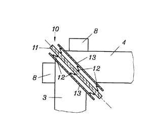
Fig. 4 shows the solution in accordance with the invention
in a schematic manner. The spacer element 10 consists of a
carrier 11 on which diaphragms 13 are attached by way of
springs 12. The stops 8 are arranged in the known manner.
The travel of the springs 12 is dimensioned in such a way
that in the case of a profile section with minimal
dimensions, i.e. with a profile section in which the
tolerance range in the direction of small length is used up
completely, a still sufficient pressing force is made
available in order to allow a secure close fit on stop 8.
On the other hand, the springs 12 are arranged in such a
way that even in the presence of a profile section 4 with
maximum length there will not be any impermissible
deformation of the profile section 4 or any other
components. Carrier 11 is rigid during the insertion of the
profile sections 3,4,, i.e. it cannot be pressed from its
set position even by different forces which may be present
on both of its sides. After the closure of the clamping
jaws, which are not shown in fig. 4, the spacer element 10
in accordance with the invention is pulled out in the known
manner from the gap between the profile sections 3, 4 and
CA 02240809 1998-06-16
instead a welding reflector, which is also not shown, is
introduced for heating the profiles so as to enable the
welding.
The invention allows the production of accurately
dimensioned window leaves or frames and door leaves or
frames from PVC profiles or the like even in cases where
profile sections, which is assumed in this case, are
subject to certain tolerances in length.