Note: Descriptions are shown in the official language in which they were submitted.
CA 02240917 1998-06-17
Conveyor For Cantilevered Loads
BACKGROUND OF THE INVENTION
The present invention relates to conveyors, and, in particular, to a conveyor
for carrying a cantilevered load. There are some conveyors known in the prior art
for carrying cantilevered loads. These conveyors usually have some type of a
conveyor frame and a cantilevered carrier for carrying the cantilevered loads. The
weight of the load and of the carrier are usually supported by the belt, roller, or other
movable element that moves the carrier along the conveyor frame. Since the weight
is carried by the moving elements, there is usually rapid wear of the conveyor. The
typical prior art arrangement also provides a rough ride for the products being
carried, and it involves substantial energy consumption. The known arrangements
also generally make it impossible or impractical to stop one carrier moving along the
conveyor without stopping the other carriers, because the carriers are generally tied
to each other in some way. This means that, if there is a slow-down with one
carrier, the entire line of carriers is slowed down, which is not desirable.
SUMMARY OF THE INVENTION:
The present invention provides a conveyor for carrying cantilevered loads
which solves many of the problems of prior art conveyors. In the present invention,
the moving belt which drives the carriers does not support the weight of the carriers
or of the loads carried on the carriers. This greatly reduces wear and energy
consumption in the conveyor system. Also, since the weight of the carriers is
supported on the stationary conveyor frame in the present invention, the products
travelling along the conveyor of the present invention get a much smoother ride, with
much less jostling of the products than in prior art conveyors.
The present invention provides a simple design for a cantilever conveyor, in
which both the conveyor frame and the carrier which rolls along the frame may bemade by extrusion. This eliminates the need for many extra parts which are
common in the prior art, thereby reducing assembly costs.
The conveyor frame of the present invention preferably has slots formed
along the carrier roller support surfaces, in order to receive wear strips. This means
that, for example, the frame may be made of aluminum, and steel wear strips may
CA 02240917 1998-06-17
be provided, thereby increasing the life of the frame. Also, the roller support
surfaces are preferably crowned, so that the carrier may seek its own position on the
frame, compensating for manufacturing tolerances.
BRIEF DESCRIPTION OF THE DRAWINGS:
Figure 1 is a schematic top view of a first conveyor system made in
accordance with the present invention;
Figure 2 is a schematic top view of a second conveyor system made in
accordance with the present invention;
Figure 3 is a rear perspective view of a portion of the conveyor frame and one
of the carriers of Figure 1;
Figure 4 is a view taken along the section 4~ of Figure 1;
Figure 4A is an enlarged view of one of the roller support surfaces of Figure
4;
Figure 5 is a view of the conveyor drive taken along the section 5-5 of Figure
1;
Figure 6 is a top view of the turntable portion of Figure 1;
Figure 7 is a view taken along the section 7-7 of Figure 1;
Figure 8 is a view taken along the section 8-8 of Figure 1;
Figure 9 is a view of a carrier stop taken along the section 9-9 of Figure 1;
Figure 10 is a view taken along the section 10-10 of Figure 9;
Figure 11 is the same view as Figure 4, but showing an alternative drive
between the belt and the carriage;
Figure 12 is a broken-away top view, partially in section, of the chain belt of
Figure 3; and
Figure 13 is a side view of the chain belt of Figure 12.
DESCRIPTION OF THE PREFERRED EMBODIMENTS:
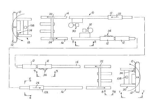
Figure 1 shows a conveyor system 10, in which carriers 12 travel along an
oval-shaped loop. There is a left elongated frame member 14, a right elongated
frame member 16, and forward and rear turntables 18, 20 at the forward and back
CA 02240917 1998-06-17
ends of the conveyor 10, respectively. Carriers 12 travelling forward along the right
frame member 16, as shown by the arrow 24, reach the rear turntable 20, and are
carried around to the left frame member 14, along which they travel the return trip,
as shown by the arrows 22. When the carriers 12 reach the forward end of the
5 conveyor 10, they are carried by the forward turntable 18 back to the right frame
member 16, and the cycle is repeated.
Each of the frame members 14,16 has a drive belt 28 (shown in later
figures), which extends along the conveyor frame and drives the carriers 12. Thebelts 28 are driven by drives 30, 32, respectively. In this preferred embodiment, the
10 belts 28 are roller chains, but other known types of belts could be used. There are
stops 34 mounted at positions along the frame members 14, 16, to selectively stop
the carriers 12. If the conveyor system 10 is part of an assembly line, used to
assemble products being carried on the carriers 12, then there may be many stops34, with each stop 34 serving as an assembly station along the conveyor's path.
Stops 34 may also be located on the tumtables 18, 20.
Figure 2 shows a similar system 1 OA, with conveyor frames 14, carriers 12,
stops 34, and drives 30, but with a different layout. In this embodiment, the
turntable 18 only carries the carriages 12 around a 90~ turn rather than 180~, as in
the first embodiment. Obviously, the conveyor frames may be arranged in a variety
of different ways without departing from the invention.
Figure 3 is a rear perspective view of the carriage 12A, of Figure 1, as it is
travelling along the right frame 16. This view shows the frame member 16, which
has an endless loop of belt 28 mounted on it for driving the carriage 12A. The
carriage 12A has several T-slots 36 along the right half of its top surface 38 and
along its right surface 40, which make it easy to attach cantilevered loads to the right
side of the carriage 12A. Two loads 43 are shown in phantom in Figure 3. The
frame member 16 also has T-slots along its left, right, and bottom surfaces 42, 44,
46. The frame member 16 also has first, second and third carrier roller support
surfaces 48, 50, 52. There is a slot 54 formed at each of the roller support surfaces
48, 50, 52, and the slots 54 receive wear strips 56. The belt 28 projects out the top
surface 58 of the frame member 16 in order to drive the carrier 12A. All the carriers
CA 02240917 1998-06-17
12 are essentially identical to the carrier 12A, and the frame members 14,16 aremirror images of each other.
Figure 4 shows greater detail of the frame 16 and carriage 12A. An
imaginary vertical axis 60 passes through the center of the belt 28 and through the
frame member 16 and the carriage 12A. The first carrier roller support 48 is located
to the left of the axis 60 and is at an acute angle a to the axis 60. The carrier 12A
has a corresponding first roller 62, with an axis of rotation 64, which is substantially
parallel to the first carrier roller support surface 48. There is a wear strip 56 in the
slot 54 of the surface 48, on which the first roller 62 rolls. The wear strips 56 are
pinned to the frame member 16 at intervals along the frame member 16 by pins 66,to ensure that the wear strips 56 do not slip relative to the frame member 16. The
mounting bolt 68 which mounts the first roller 62 on the carriage 12A includes an
eccentric (not shown), which permits slight adjustment of the position of the roller 62.
The second carrier roller support surface 50 is to the right of the axis 60 and
is at an acute angle ~ to the horizontal. Since the second support surface 50 slopes
downwardly away from the central axis 60, any debris falling onto that surface will
tend to roll or slide off. The carriage 12A has a corresponding second roller 70,
which has an axis of rotation 72 that is substantially parallel to the second roller
support surface 50. As the second roller 70 rolls along the surface 50, it tends to
want to travel downhill, due to the angle of the surface 50, which tends to pull the
first roller 62 toward its support surface 48. Since the first support surface 48 is at
an outward angle from the vertical, it prevents the carriage 12A from lifting vertically
off of the frame 16 during operation of the conveyor. However, the carriage 12A and
frame 16 are designed so that the carriage 12A can be removed from the frame at
any point along the frame simply by rotating it counterclockwise and then lifting it up.
The third carrier roller support surface 52 is shown, in this preferred
embodiment, as being located below the second roller support surface 50, and to
the right of the axis 60, and oriented substantially vertically. The purpose of this
third surface 52 is to counter the torque created by the cantilevered load 43. While
the position and orientation shown here are prefened for that purpose, it will be
understood by those skilled in the art that this third surface 52 could have different
CA 02240917 1998-06-17
locations and orientations and still perform its function. The carrier 12A has acorresponding third roller 74 which has an axis of rotation 76 that is substantially
parallel to the third roller support surface 52.
The rollers 62, 70, 74 all project from the inner surface 80 of the carriage 12A,
while the loads 43 are supported on the outer surface 81 of the carriage 12A. Itshould be noted that the three roller support surfaces 48, 50, 52 are not parallel to
each other and lie at angles to each other, so that they provide different types of
support and guidance for the carriage 12A as it rolls along the frame 16. The first
roller guides the carriage 12A and prevents the carriage from lifting up off of the
frame during operation of the conveyor. The second roller 70 supports the weight of
the carriage 12A and of anything mounted on the carriage 12A, so that none of the
weight is carried on the chain 28. The third roller 74 guides the carriage and
counters the torque of the cantilevered load.
There is a spring-mounted shoe 78 projecting from the inner surface 80 of the
carriage 12A, which contacts two adjacent large, central rollers 89 of the belt 28 and
serves as a belt follower, so that the carriage 12A can be driven by the belt 28.
There is a bumper 82 on the back surface of the carriage 12A, so that, if another
carriage 12 bumps into this carriage 12A, the bumper 82 will absorb the impact. The
force of the spring 84 may be adjusted to increase or decrease the force with which
the shoe 78 pushes down against the chain 28, depending upon the type of load tobe carried. Since the weight of the load is carried on the frame 16, the force need
only be suffficient to provide enough friction between the shoe 78 and the belt 28 to
drive the carriage 12A.
The belt 28 is a roller chain, with small rollers 86 on the outside of the
sidebars 88 and staggered, large, central rollers 89 between the sidebars 88. (The
preferred chain belt 28 is shown in more detail in Figures 12 and 13.) The small,
outer rollers 86 roll on tracks 90, 92, 94, 96, mounted on the conveyor frame 16.
The upper tracks 90, 92 are held in slots 98,100 by split roll pins 102. These upper
tracks 90, 92 can be inserted through the top opening of the frame 16. The lowertracks 94, 96 fit in slots 103, 104 and are slid in from the end of the frame 16. Since
the weight of the carriage 12A is supported entirely on the frame 16, the load on the
CA 02240917 1998-06-17
belt 28 is greatly reduced from the prior art designs in which the weight of the carrier
and of the products are carried by the belt. This greatly reduces the wear of the belt
28 and of the rails 90, 92 from prior art designs.
Figure 4A is an enlarged view showing the upper left, first roller support
surface 48 of the conveyor frame 16. In this view, it can be seen that the roller
support surface 48 is crowned. This gives the wear strip 56 some room to rock inthe slot 54. All of the roller support surfaces 48, 50, 52 are preferably crowned in
this manner. This permits the carriage 12A to find its path along the frame 16,
compensating for slight manufacturing tolerances.
Figure 5 shows one of the belt drives 30. It can be seen that the drive 30
drives the lower run of the belt 28, so it is completely below the carriages 12 and
does not interfere with the travel of the carriages 12 along the frame 16. The belt 28
is driven by a drive sprocket 106. For different types of belts, different known drives
may be used.
Figures 6 and 7 show one of the turntables 20. The tumtable 20 includes a
frame section 16A, which can be aligned with either of the frames 14,16, depending
upon the position of the turntable 20. The turntable 20 rotates 180~, back and forth,
about an axis 108, first aligning with the frame 16 and accepting carriages 12 from
the frame 16, then pivoting to align with the frame 14, and discharging carriages 12
onto the frame 14. The section of frame 16A on the turntable 20 is essentially the
same as the frames 14,16. It preferably includes a stop 34. It includes its own
drive belt 28A (shown in Fig. 7), to drive the carriages 12 that are on the turntable
20, and its own drive motor (not shown) to drive the belt 28A.
Figure 8 shows the guide wheel 110 at the back end of the frame 16, which
supports the end of the belt 28. There is a similar guide wheel (not shown) at the
front end of the belt 28.
Figures 9 and 10 show one of the stops 34. The stop 34 is mounted on the
T-slots on the inner surface 42 of the frame member 14. It includes a pivot arm 112,
which pivots up to contact the carrier 12 and stop the carrier 12. Since there is only
a small frictional force between the shoe 78 and the chain 28, the chain 28 can just
move past the carrier 12, with the carrier 12 stopped. The pivot arm 112 is
CA 02240917 1998-06-17
operated by a pneumatic actuator.
It is also possible to provide a mechanism (not shown) to lift the pin 114 on
which the shoe 78 is mounted, which will lift the shoe 78 off of the belt 28 in order to
completely eliminate the friction force between the shoe 78 and the belt 28 when the
carriage 12 is stopped.
While the embodiment shown in Figures 1-10 relies on friction between the
shoe 78 and the belt 28 to drive the carriage 12, it would be possible to use other
types of belt followers to transmit the driving force to the carriages 12. For example,
there could be a magnetic force between the shoe 78 and the belt 28. If an
electromagnet were used to create the magnetic field, the electromagnet might beturned off when the carriage 12 is stopped in order to eliminate the driving force on
the stopped carriage 12.
Figure 11 shows an alternative embodiment, in which the shoe 78 continues
to be the belt follower, but it follows the belt 28 by being pushed by a pusher arm
116 on the belt 28 rather than by friction with the top surface of the belt 28. In this
embodiment, the pin 114 would have to be lifted up to lift the shoe 78 above thepusher 116 in order to allow the carriage 12 to stop while the beit 28 continues to
move. Figure 11 also shows one of the pusher arms 116 in the lower run of the
chain 28.
It will be obvious to those skilled in the art that modifications may be made tothe embodiments described above without departing from the scope of the present
invention.