Note: Descriptions are shown in the official language in which they were submitted.
CA 02240928 1998-06-17
CONTAINER FOR STORING TABLETS
The present invention relates to a container for
storing pills.
Such containers are well known and have long been
used for storing pills or tablets, particularly pills for
medicinal purposes. In many cases persons who regularly take
medicine have reduced mobility, particularly fine motor
function, as a result of illness or old age, and it is there-
fore desirable to be able to open or close such containers
without unnecessary complicated rotary manipulation. The wrap
of the screw-threads on the lid and the container part should
therefore be as short as possible. At the same time it is
important for the lid to seal the container tightly in order
to protect the contents from the surrounding air. This sealing
function is achieved mainly by the threads cooperating with
each other and in order to achieve satisfactory sealing, it is
therefore important for the wrap of the threads to be as large
as possible, a wrap of several revolutions often being required.
This requirement is in opposition to the need mentioned in the
introduction, of being able to open the container with as little
angle of rotation as possible. Conventional closures have
either involved a compromise between these two demands or have
been aimed at satisfying only one of them and disregarding the
other.
The purpose of the present invention is to endeavour
to solve this problem and provide a container which is both
easy to open and also satisfies the demand for good sealing.
1
24992-161
CA 02240928 2005-04-O1
21209-450
2
The invention provides a container for storing
pills or tablets, comprising a container part with an
opening and a lid to close the opening, said opening being
surrounded by a cylindrical portion of the container part,
said portion being provided externally with at least one
screw-thread and said lid having a cylindrical portion
provided internally with at least one thread arranged to
cooperate with the at least one screw-thread provided on the
cylindrical portion of said container part to enable the lid
to be screwed on and oft the container part, each of said
threads having an angle of wrap of 270° ~ 45°, said lid
having an inner bottom with a circular groove into which an
axially external part of the cylindrical portion of the
container part is inserted when the lid is fully screwed on;
to be in sealing contact with the lid along at least three
circular sealing lines, said groove being defined by one
cylindrical side wall formed by an annular flange extending
axially from said inner bottom of said lid, one side wall
formed by an inner wall portion of said lid and surrounding
said cylindrical side wall, and by a substantially flat
bottom extending between these walls, said substantially
flat bottom being provided with a ridge, wherein said side
wall formed by an inner wall portion of said side wall is
conical and a flat surface of an outer edge of said external
part of said cylindrical portion is pressed against said
ridge and its point is slightly deformed when said lid is
fully screwed onto said cylindrical portion of said
container part.
Thanks to the main sealing function being located
at the outer edge of the container part in cooperation with
surfaces on the bottom of the lid, the contact between them
being along three circular sealing lines, a perfectly
satisfactory sealing function is achieved without the
CA 02240928 2005-04-O1
21209-450
2a
sealing effect from the threads engaging in each other
having to be considered. Since the sealing aspect for the
threads in a container according to the invention can be
entirely neglected, these can be given minimum length
corresponding to that necessary to properly ensure that the
lid remains on the container part and is not accidentally
screwed off. It has thus been possible to make these with
an extension of approximately 270° or even less.
According to another preferred embodiment, the
container is provided with a plurality of threads,
preferably three on each part, which further simplifies
manipulation, particularly when screwing on the lid.
The invention is particularly intended for use
with containers manufactured out of plastic. This further
,increases the sealing function since, due to the relatively
great deformability of the material, the sealing lines will
be somewhat extended in transverse direction and in practice
form ribbon-shaped sealing surfaces.
The invention is extremely suitable for use with
lids of security type where an axial force pressing the lid
against the container part is required to enable the lid to
be screwed off.
According to yet another preferred embodiment of
the invention, the lid is provided with a lightly applied
strip or collar providing an indication as to whether the
container has been opened or not.
CA 02240928 2005-04-O1
21209-450
3
The above and other advantageous embodiments of the invention are
defined in the accompanying claims.
The invention will be explained in more detail in the following
description of a preferred embodiment with reference to the
accompanying drawings, in which
Figure 1 shows a longitudinal section through the container part of a
container according to the invention,
Figure 2 is a view of the container part in Figure 1, seen from above,
Figure 3 shows a partial longitudinal section through the lid of a
container according to the invention in a first position,
Figure 4 shows a corresponding section through the lid in Figure 3 in.a
second position,
Figure 5 shows an alternative embodiment of the lid in a section
equivalent to that shown in Figure 3,
Figure 6 is a view of the lid in Figure 5 seen from above,
Figure 7 is an enlarged partial section of Figure 3.
The container part 1 in Figure 1 is a jar for pills and is manufactured from
high
density (HD) polyethylene. It has an upper cylindrical portion provided with
three threads 3, 4, 5, each 'with an angle of wrap of 270a and a pitch of
approximately 1:10. In .the embodiment shown the lower part of the
container in which the pills are stored is also cylindrical but could have
any shape. Between the cylindrical portion 2 provided with threads '3,
4, 5, and the lower part of the container 1 is a cylindrical neck portion 6,
provided with four bosses ?. These. can be seen most clearly in Figure 2
and their function will be described: later on.
CA 02240928 1998-06-17
WO 97/22534 PCT/SE96/01563
4
Figure 3 shows the lid 8, 9 of the container part 1 shown in Figures 1
and 2. The Iid consists of an inner part 8 and an outer part 9 and is
made of polypropylene. The inner part 8 is provided with three
threads 10, 11, 12 on its cylindrical part, each having an angle of wrap
and pitch corresponding to the threads on the container part 1 so that
they can be screwed info each other. The lid is of security type,
constructed so that the Iid parts 8, 9 must be pressed together axially for
the inner part 8 to accompany the outer part 9 when this is turned in
opening direction. Figure 3 shows the lid in this compressed position.
I0
When the lid parts 8, 9 are not compressed they assume the position
shown in Figure 4 in relation to each other. In this position the outer
part 9 will only cause the inner part 8 to turn in closing direction,
whereas the outer part 9 will rotate freely about the inner part if turned
in opening direction. Connecting members 13 and 14 on the two parts
only permit turning resulting in opening when the lid parts are
compressed.
The side of the inner part 8 facing the container part is provided with a
strip or collar 15 secured with the aid of a number of tongues 17. These
tongues are thin and can be broken with relatively little force. Four
bosses 16 are arranged on the inner side of the collar. When the Iid 8, 9
is screwed onto the container part 1 the collar 15 is locafed around the
neck portion 6 of the container part 1. The bosses on the collar 15 and
the bosses 7 on the neck portion of the container 1 are arranged to hook
into each other when the Iid is turned in opening direction. W he n
turning continues past this position, where the ring 15 is retained by
the cooperating bosses 7 and 16, the tongues are torn off so that the
collar 15 is separated from the inner part 8 of the lid and assumes a
position resting around the neck portion 6 of the container part. This
tearing of the collar 15 from the inner part 8 of the lid occurs the first
time the lid 8, 9 is removed from the container part 1. The fact that it is
separated from the lid thus serves the function of indicating that the
container has been opened.
CA 02240928 1998-06-17
WO 97/22534 PCT/SE96/01563
As can be seen in Figures 4 and 5, the cylindrical outer surface of the
outer part 9 is shaped with peaks 18 and valleys 19 in a wave pattern in
peripheral direction in order to facilitate turning.
'' S In the embodiment according to Figures 6 and 7 the outer part 9 of the
lid is provided on its upper side with gripping means 20 which for
some people offers an alternative that facilitates turning. The gripping
means 20 is in the form of a ring standing up from the lid and having
diametrically opposed slits 21. The lid can be opened with the aid of
these by pressing the container against the edge of a slab-shaped object,
e.g. the edge of a table. With the edge of the table engaged in the slits
21, the container is easily opened by turning the container part 1 while
the lid is prevented from turning by the edge of the table.
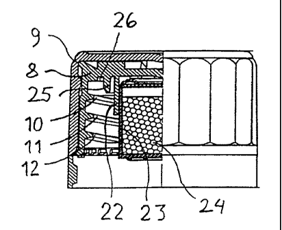
As can be seen in Figure 3 the inner part 8 of the lid is provided at the
bottom with an annular holder in which a container 22 with desiccant
material 23 can be applied.
The inner part 8 of the lid is also provided with an annular flange 25
and an annular groove 26. When the lid 8, 9 is screwed onto the
container part 1, the outer edge 27 of the cylindrical pardon 2 of the
container part extends into the annular groove 26 and seals against the
adjacent surfaces thereof.
Figure 7, which is an enlargement of a section through the portion
around the flange 25 and groove 26, shows how the outer edge 27 of the
container part cooperates seaiingly with the inner lid 8.
The annular groove 26 is limited in radial direction on its inner side by
the outer cylindrical surface of the flange 25 and on its outer side by a
conical surface 29, half the top angle of which is approximately 25~. The
bottom 30 of the groove is substantially flat and is provided
substantially centrally with an annular ridge 31 having triangular cross
_r
section. The depth of the groove is approximately 5 mm and its
CA 02240928 1998-06-17
WO 97/22534 PCT/SE96/01563
6
breadth is approximately the same. The ridge has a height of
approximately 0.3 mm and a top angle of approximately 60~.
When the lid 8 is fully screwed onto the cylindrical portion 2 of the
container part, active sealing occurs along three active sealing lines A,
B, C running annularly between the Iid part 8 and the outer edge 27 of
the cylindrical portion 2. The threads permit screwing until the
screwing motion is stopped by contact along these lines. The groove is
so dimensioned that contact occurs substantially simultaneously along
the lines A and B. The contact force at the line A provides an efficient
seal against the corresponding corner of the edge 27 which is thus
slightly deformed. Due to the conical shape of the surface 27 the contact
force at A acquires a radial component which presses the outer end of
the annular portion 2 inwards to abut the inner surface 28 of the flange
25 so that an efficient sealing Iine with a contact force arises in the
area C. The flat surface of the edge 27 will be pressed against the ridge
31 and its point will be slightly deformed, whereupon an efficient
sealing line is also achieved in the area B.
Thanks to these three contact Iines A, B, C, where contact a n d a r
pressure occurs along all three, efficient sealing is obtained which
eliminates the need for the screw-threads to be given any sealing
function. The figure also shows a fourth sealing line D between the
conical surface 29 and the corner of a section of the cylindrical portion 2
having slightly larger diameter than at its outer edge. Sealing along
this Iine D is Iess efficient, however, and is deemed passive since the
true contact force in axial direction occurs along the Ianes A and B, this
force preventing further penetration of the cylindrical portion 2 into
the groove 26. Any contact occurring along the Iine D must therefore
be rather light.
The embodiments described above are only intended as examples to
explain the inventive concept and shall not, therefore, be attributed any
limiting significance. The invention can be modified in various ways
and is limited only by the protective scope defined in the main claim.
CA 02240928 1998-06-17
WO 97/22534 PCT/SE96/01563
7
It should be particularly emphasised that it is not limited to use with a
lid of security type but may also be used for simple screw-on lids.