Note: Descriptions are shown in the official language in which they were submitted.
CA 02240936 1998-06-18
1240.00001
-1-
VARIABLE DECORATIVE TREATMENT
BACKGROUND OF THE INVENTION
TECHNICAL FIELD
The present invention is directed to a decorative treatment, as
for windows, and, more particularly, to a decorative treatment having
interchangeable elements.
BACKGROUND ART
Windows are placed in all types of buildings permitting exter
nal light to illuminate a room and also allowing the occupant to view the
outside. While windows are generally designed to be primarily functional
in nature, many residential building owners, and some commercial building
owners, desire their windows to be aesthetically pleasing as well as func-
tional. In a commercial setting, this helps to maintain a pleasant, relaxed
working environment, presumably boosting the morale of the employees
and increasing the quantity and quality of their work. In a residential set-
ting, aesthetically pleasing windows add a sense of personality and warmth
to the home.
Leaded and bevelled glass are two examples of materials used
to give windows an aesthetically pleasing appearance. Further, grid sys-
terns have been developed which are mounted inside a double window
pane unit and securely hold decorative art glass panes in place. However,
a drawback with the above examples is that they may not permit a home
owner to readily and easily change the decorative appearance of the win-
dow. A home owner may wish to change the decorative features of his/her
a
CA 02240936 2004-04-13
-2-
windows in accordance with the holidays or the changing seasons, or simply
because he/she feels like it.
SUMMARY OF THE INVENTION
A decorative window assembly is provided including a frame having
spaced apart frame elements between which a display space is defined, a first
element having a first appearance, and a receptacle and projection defined on
each
of the frame and first elements cooperating to removably maintain the first
element
in a fist predetermined relationship at a first location on the frame. A
second
element is also provided having a second appearance, with a receptacle and
projection defined on each of the frame and second elements cooperating to
removably maintain the second element in a second predetermined relationship
at
the first location on the frame, whereby the first and second elements can be
selectively interchangeably at the first location to selectively change the
overall
appearance of the frame.
The invention in one broad aspect pertains to a kit comprising a frame
having first and second spaced apart frame elements between which a display
space is defined and visible as viewed from a first vantage point, a first
display
element, a receptacle and projection defined one each on the first and second
frame elements and the first display elemenf cooperating to releasably
maintain the
first display element in a first predetermined relationship at a first
location in the
display space. The first display element is in the first predetermined
relationship
at the first location performing primarily a decorative function and having a
first
decorative appearance as viewed from the first vantage point. There is a
second
display element and a receptacle and projection are defined one each on the
first
a
CA 02240936 2004-04-13
- 2A -
and second frame elements and the second display element cooperates to
releasably maintain the second display element in a second predetermined
relationship at the first location in the display space with the first display
element
absent from the first location. The second display element is in the second
predetermined relationship at the first location performing primarily a
decorative
function and having a second decorative appearance as viewed from the first
vantage point. The first and second display elements are capable of being
selectively interchangeably displayed at the first location to selectively
change the
overall decorative appearance of the first and second frame elements as viewed
from the first vantage point.
' The invention comprehends the frame and display elements in
combination.
In one form of the present invention, the receptacle and projection
defined on each of the frame and first and second elements includes a dove-
tail
connection between the frame and first and second elements.
In another form of the present invention, the spaced apart frame
elements include a plurality of receptacles/projections defined thereon at
predetermined locations along their respective lengths. The first and second
elements each have a pair of projections~receptac(e, whereby the first and
second
elements can be selectively interchangeably displayed at any of the
predetermined
locations to change the overall appearance of the frame.
CA 02240936 2004-04-13
-3-
In still another form of the present invention, the spaced apart frame
elements have opposing inner surfaces defining the display space, with each
opposing inner surface having a channel extending lengthwise along the
respective
frame element. The first and second elements each have a pair of flanges
removably receivable in the channels for guided sliding translatory movement
of the
first and second elements in the display space relative to the frame:
In still another form of the present invention, the first and second
elements are snap-fit to the frame.
In still another form of the present invention, a window is provided
having inner and outer surfaces, with the frame attached to the inner surface
of the
windoinr.
Accordingly the present invention seeks to provide a decorative
window assembly with readily interchangeable decorative features.
Further the present invention seeks to provide a decorative window
assembly permitting a home owner to custom decorate their windows.
Still further the present invention seeks to provide an easy to instal!
decorative window assembly.
Other aspects, features and advantages of the present invention can
be obtained from a study of the application, the drawings, and the appended
claims.
CA 02240936 1998-06-18
1240.00001
-4-
BRIEF DESCRIPTION OF THE DRAWINGS
Fig. 1 is a front elevation view of a first embodiment of the
decorative assembly of the present invention, including a frame and an
exemplary display element;
Fig. 2 is a cross-sectional view taken along line 2-2 in Fig. 1;
Fig. 3 is a cross-sectional view taken along line 3-3 in Fig. 1;
Fig. 4 is a cross-sectional view taken along line 4-4 in Fig. 1;
Fig. 5 is a front elevation view of a second embodiment of the
decorative assembly of the present invention, including a frame and an
exemplary display element;
Fig. 6 is a cross-sectional view taken along line 6-6 in Fig. 5;
Fig. 7 is a cross-sectional view similar to that shown in Fig. 6,
but including a modification to the frame;
Fig. 8 is a cross-sectional view taken along line 8-8 in Fig. 5;
Fig. 9 is a side elevation view of a first embodiment of the
decorative element;
Fig. 10 is a side elevation view of a second embodiment of the
decorative element;
Fig. 11 is a side elevation view a third embodiment of the
decorative element;
Fig. 12 is a side elevation view of a fourth embodiment of the
decorative element;
Fig. 13 is a fragmentary front elevation view of the decorative
window assembly attached to a window frame, depicting an exemplary
decorative design consideration;
CA 02240936 1998-06-18
1240.00001
-5-
Fig. 14 is a fragmentary front elevation view of the decorative
window assembly attached to a window frame, depicting an alternative
decorative design consideration;
Fig. 15 is a front elevation view of a third embodiment of the
decorative assembly of the present invention, including a sash, a frame and
exemplary display elements;
Fig. 16 is an enlarged, front elevation view of the exemplary
display element depicted in Fig. 15; and
Fig. 17 is an enlarged, siae elevation view of the third embodi-
ment of the decorative assembly of the present invention.
DETAILED DESCRIPTION OF THE PREFERRED EMBODIMENTS
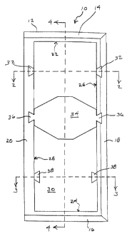
With reference to Figs. 1-4, one form of decorative assembly,
according to the present invention, is shown generally at 10. The assembly
10 includes a frame 12 defined by elongate side elements 14,16,18,20.
The frame elements 14,16,18,20 are joined at their ends, with the ele-
ments 14 and 16 spaced and parallel to one another and the elements 18
and 20 spaced and parallel to one another, to define generally a rectangular
configuration. However, it should be understood that other geometric
configurations of the frame 12 are also contemplated. The frame elements
14,16,18, 20 include inner surfaces 22,24,26,28, respectively, which
define a display space 30. A plurality of dove-tail shaped receptacles 32
are formed in the frame elements 18 and 22 at predetermined locations
along their lengths. A display element 34 (see Fig. 9) is disposed in the
display space 30 and includes spaced dove-tail shaped projections 36
complementary to and receivable one each in the receptacles 32 formed in
CA 02240936 1998-06-18
1240.00001
-6-
the frame elements 18 and 20. By directing the projections into the recep-
tacles 32 at selected locations along the length of the frame element
18,20, the display element 34 may be press-fit into a predetermined
relationship with the frame 12 at any of the plurality of predetermined
locations established by the positions of receptacles 32.
Alternatively, the receptacles 32 may be replaced with dove-
tail shaped projections 38 projecting from the inner surfaces 26,28 of
frame elements 18,20. Of course, if the frame elements 18,20 include
projections 38, the display element 34 (see Fig. 10) would need to be
modified to include dove-tail shaped receptacles 40 replacing the
projections 36. As before, the display element 34 would simply be press-
fit to the frame 12 and held in place by the cooperating projections 38 and
receptacles 40 on the frame elements 18,20 and display element 34.
While the display element 34 is depicted as having a geometric
configuration, it should be understood, and will become more readily
apparent, that other design configurations for the display element 34 are
also contemplated. Moreover, it should be understood, and will become
more readily apparent, that the decorative assembly 10 of the present
invention is designed to be utilized with a plurality of display elements 34,
which may be selectively interchangeably mounted at any of the
predetermined locations as determined by the receptacles 32/projections 38
on the frame 12.
Referring now to Figs. 5-8, a second embodiment of the
decorative assembly 10' of the present invention is shown, with like
elements having the same reference number and elements which
correspond but have been slightly modified indicated with a prime ('1.
CA 02240936 1998-06-18
1240.00001
_7_
Frame elements 18' and 20' have been modified to include channels 42
formed on their inside surfaces 26' and 28', respectively, with the channels
42 extending generally the entire length of the frame elements 18',20'.
The display element 34' has been modified (see Fig. 11) to include
projections 44 extending peripherally therefrom. Preferably, the display
element 34' is made of a resilient material and is snap-fit to the frame 12'
in the display space 30. The projections 44 on the decorative element 34'
are received in channels 42 on the frame elements 18',20' and maintain
the decorative element 34' within the frame 12' in a predetermined
relationship while allowing guided sliding translatory movement of the
decorative element 34' in the directions of arrow 46 relative to the frame
12' .
Alternatively, as shown in Fig. 7, a raised rib 48 may be
formed on the inner surfaces 26',28' of the frame elements 18',20',
replacing the channels 42. In this embodiment, the decorative element 34'
(see Fig. 12) would include slots 50 replacing the projections 44.
Assembly and movement of the decorative element 34' would be
accomplished in the same manner as before.
Figs. 13-14 depict two (2) of the virtually infinite design
configurations for the decorative window assembly 10,10' of the present
invention. For instance, Fig. 13 depicts the decorative assembly 10,10'
attached to an interior surface of a window shown generally at 52. The
assembly 10,10' is attached along the edge of the window 52 near the
frame 54, and may be attached via any conventional mounting means.
The design configuration shown in Fig. 13 depicts a plurality
of similarly configured geometric shapes used as the decorative elements
CA 02240936 1998-06-18
1240.00001
_g_
34,34'. Whereas in Fig. 14, alternating design configurations are utilized
for the decorative elements 34,34'. It should be noted that the design
configurations depicted in Figs. 13 and 14 can be utilized with either
embodiment of the decorative assembly 10,10'. That is, the display
elements 34,34' may be attached to the frame 12,12' via cooperating
projections and receptacles whereby the display elements 34 would be
releasably held in fixed predetermined locations along the frame 12, or
alternatively, the display elements 34' may be mounted to the frame via
cooperating channels and ribs, whereby the guided sliding translatory
movement of the decorative elements 34' with respect to the frame 12'
could be effectuated.
Referring now to Figs. 15-17, a third embodiment of the
decorative assembly 10" of the present invention is shown, with like
elements having the same reference number and elements which
correspond but have been slightly modified indicated with a double prime
("). The decorative assembly 10' includes top 56 and bottom 58 frame
elements which are attached to the frame 54. The top 56 and bottom 58
frame elements include dove-tail shaped channels 60 formed on their inside
surfaces 62 and 64, respectively, with the channels 60 extending generally
the entire length of the frame elements 56,58. The display element 34"
includes dove-tail shaped projections 66 extending from opposite sides
thereof. The dove-tail connection between the projections 66 on the
display element 34" and each of the channels 60 in the top 56 and bottom
58 frame elements, maintains the decorative element 34" in a
predetermined relationship while allowing guided sliding translatory
movement of the decorative element 34" in the directions of the arrow 68
CA 02240936 1998-06-18
1240.00001
_g_
relative to the top 56 and bottom 58 frame elements.
The bottom frame element 58 includes a bevel 70 formed on
the side, shown generally at 72, viewable from the interior of the window,
while the top frame element 56 includes a bevel 74 on the side, shown
generally at 76, which abuts the window sash 52 and frame 54. It should
be noted that both the top 56 and bottom 58 frame elements may also be
squared or shaped or designed to match a window manufacturer's
specifications for their optional grilles. Further, both the top 56 and bottom
58 frame elements may be bevelled to match a window manufacturer's
specifications on a window sash where the styles and rails bevel toward
the glass. This will assure a proper fit for the decorative assembly 10" to
set into the frame 54 and appear to be a part of the window sash 52.
When the decorative assembly 10,10',10" is mounted to a
window 52, the decorative elements 34,34',34" produce silhouettes as the
outside light shines in through the window 52. The interchangeability of
the decorative elements 34,34',34" permits a home owner to customize
their window treatments, adding personality and comfort to the home. The
decorative elements 34,34',34" may be changed in accordance with the
holiday seasons to produce a Christmas or Easter decorative theme, or with
the change of seasons, or even change or accent the decor of the room.
Various themes could include southwestern, animals, nature, florals, sports,
arts, music and/or ballet.
While the decorative assembly 10,10',10" is shown attached
to a window 52, it should be noted that the decorative assembly
10,10',10" is not intended to be limited to use in this manner. The
decorative assembly 10,10',10" can be mounted anywhere in a home or
CA 02240936 1998-06-18
1240.00001
-10-
room to add aesthetically pleasing features thereto. For instance, the
decorative assembly 10,10',10" could be used as a pot rack, a wall border,
or merely as a wall hanging adding aesthetically pleasing features to a
room.
While the invention has been described with particular
references to the drawings, it should be understood that various
modifications can be made without departing from the spirit and scope of
the present invention.