Note: Descriptions are shown in the official language in which they were submitted.
CA 02241042 1998-06-19
WO 97!24054 PCTIUS96I20386
APPARATUS FOR DISPENSING MULTIPLE PRODUCTS
FROM A SINGLE TISSUE ROLL HOLDER
FIELD OF THE INVENTION
The present invention relates to an apparatus for dispensing toilet tissue in
conjunction with at least one other product. The invention has even further
relation to
such an apparatus which is readily attachable to an ordinary toilet tissue
roll holder
without the need for additional adhesives, hardware or the like.
BACKGROUND OF THE INVENTION
Ordinary toilet tissue roll holders have been well known for many years and
are
found in almost every household. Typically, these toilet tissue roll holders
comprise a
spring-loaded spindle which is inserted into a rigid member having a pair of
opposing
1 S holes. These holes are either recessed within a bathroom wall or extend
from a bathroom
wall.
Recently there has been a desire to supplement ordinary toilet tissue with
other
personal products, such as wet toilet wipes. Consumers have shown a preference
for
having wet toilet wipes near the toilet tissue in the bathroom and -- thus --
easily
accessible. However, using products such as wet toilet wipes requires another
dispenser,
in addition to the spindle used to dispense the toilet tissue.
There have, therefore, been attempts to provide an apparatus that can dispense
both ordinary toilet tissue and at least one other product. One example of
such an
apparatus is given in United States Patent 3,799,467, issued to Bauman on
March 26,
1974. Bauman discloses a toilet tissue holder and shelf combination. However,
Bauman
has the drawback that the toilet tissue and shelf combination are adapted to
be attached to
the side wall of a flush tank or other vertical support means, rather than to
the existing
tissue roll holder. Although the pre-existing roll holder is still present in
the bathroom, it
is not utilized.
One solution to this problem was to provide an apparatus for dispensing toilet
tissue and another product, which apparatus is readily attachable to an
ordinary toilet
tissue roll holder. An example of this attempt is illustrated by U.S. Patent
3,943,859,
issued to Boone on March 16, 1976. Boone discloses a shelf like device which
is readily
attachable to an ordinary toilet tissue roll holder and does not interfere
with the dispensing
of the toilet tissue. However, Boone has the drawback that the shelf is
unstable and
CA 02241042 2001-11-07
2
requires adhesives or other hardware to hold the shelf in place. Boone
requires
considerable installation time, becomes permanent, and therefore would not be
commercially acceptable. Furthermore, the Boone device cannot attach itself to
recessed roll holders and therefore is not applicable to a wide range of
existing roll
holders.
Another example of an apparatus for dispensing toilet tissue and another
product and which is readily attachable to an ordinary toilet tissue roll
holder is
illustrated by U.S. Patent 3,7~4,253, issued to Megdall on February 26, 1974.
Megdall discloses a toilet paper roll holder further equipped to support a box
of
tissues. Megdall has the drawback of using resilient rod members that need to
be
disposed against a wall in order to put pressure against the box of tissues to
be
supported. This pressure makes the structure unstable and may damage the wall.
While Megdall is capable of supporting a roll of toilet paper and a box of
facial
tissues or the like, it is not wc;ll adapted to carry irregularly shaped
products, such as
commonly packaged wet toilet wipes.
Therefore, there has been a desire to provide a stable apparatus for
dispensing
toilet tissue and at least one other product and which is readily attachable
to an
ordinary toilet tissue roll holder without the need for any additional
hardware,
adhesives or the like.
In accordance with one embodiment of the present invention there is provided
an apparatus for dispensing toilet tissue and at least one other product, the
apparatus
being attachable to a wall-mounted toilet tissue roll holder comprising a
spindle of the
roll holder and a member having a pair of opposing holes for receiving the
spindle of
the roll holder, the apparatus comprising:
a top wall and two opposing side walls spaced apart by the top wall, all of
which are connected together to form a housing, the housing having two
substantially rigid members joined thereto for attaching the housing to the
roll
holder, each of the rigid members being articulably hinged to the housing to
be
articulated from a position substantially parallel with a wall to which the
roll
holder is affixed to a position outwardly extended from the housing, each of
the members having at least one slot therein for receiving the spindle of the
roll holder such that when the apparatus is attached to the roll holder the
apparatus is secured in substantially fixed relation to the roll holder, the
housing further including a structure for receiving at least one roll of
toilet
tissue, the top wall being adapted to receive an additional product.
CA 02241042 2001-11-07
2a
In accordance with another embodiment of the present invention, there is
provided an apparatus for dispensing toilet tissue and a personal cleansing
product,
the apparatus being attachable to a wall-mounted toilet tissue roll holder
comprising a
spindle of the roll holder and a member having a pair of opposing holes for
receiving
the spindle of the roll holder, the apparatus comprising:
a top wall and two opposing side walls spaced apart by the top wall, all of
which are connected together to form a housing, the housing including a first
device and a second device for attaching the housing to the roll holder in a
secured and substantially fixed relation thereto, the housing further
including a
structure for receivin~; at least one roll of toilet tissue, the top wall
being
adapted to receive an additional product,
the first device comprising a pair of opposing and substantially co-extending
slots, one on each of the opposing side walls of the housing, for receiving
the
spindle of the roll holder, and
1 S the second device comprising two substantially rigid members joined to the
housing, each of the members being articulably hinged to the housing to be
articulated from a position substantially parallel with a wall to which the
roll
holder is affixed to a position outwardly extended from the housing, each of
the members having at least one slot therein for receiving the spindle of the
roll holder.
In accordance with another embodiment of the present invention, there is
provided an apparatus for dispensing toilet tissue and a personal cleansing
product,
the apparatus being attachable to a wall-mounted toilet tissue roll holder
comprising a
spindle of the roll holder and a member having a pair of opposing holes for
receiving
the spindle of the roll holder, the apparatus comprising:
a top wall, a back wall, and two opposing side walls spaced apart by the top
wall, all of which are connected together to form a housing, the housing
including a first device and a second device for attaching the housing to the
roll holder in a secured and substantially fixed relation thereto, the housing
further including a structure for receiving at least one roll of toilet
tissue, the
top wall being adapted to receive an additional product,
the first device comprising a pair of opposing and substantially co-extending
slots, one on each of the opposing side walls of the housing, for receiving
the
spindle of the roll holder, and
the second device comprising two substantially rigid members joined to the
housing, each of the members being articulably hinged to the housing to be
CA 02241042 2001-11-07
2b
articulated from a position substantially parallel with a wall to which the
roll
holder is affixed to a position outwardly extended from the housing, each of
the members having at least one slot therein for receiving the spindle of the
roll holder.
S
BRIEF DESCRIPTION OF THE DRAWINGS
While the specification concludes with claims particularly pointing out and
distinctly claiming the subject invention, it is believed that the same will
be better
understood from the following description taken in conjunction with the
accompanying drawings in which:
CA 02241042 2001-11-07
3
Figure 1 is a perspective view of the apparatus in accordance with the present
invention.
Figure 2 is a view similar to Figure 1 showing the apparatus attached to an
ordinary outwardly extending toilet tissue roll holder.
Figures 3 and Figures 4 are views similar to Figure I showing the apparatus
attached to a recessed toilet tissue: roll holder.
Figure 5 is a perspective view of the embodiment of the apparatus adapted to
receive two rolls of toilet tissue and another product.
Figure 6 is similar to Figure 1 and shows the apparatus having nubs.
Figure 7 is similar to Figure 5 and shows the apparatus having a concave
support.
DETAILED DESCRIPTION OF THE INVENTION
Referring now to the drawings in detail wherein like numerals indicate the
same
element throughout the views, there is shown in Figure 1 a perspective view of
one
1 S embodiment of an apparatus 10 for dispensing toilet tissue and at least
one other product
in accordance with the present invention.
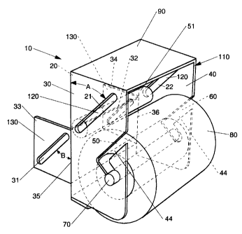
Apparatus 10 has a top wall 90 and two opposing side walls 30 and a0 all of
which
are connected together to form a housing 110. In the preferred embodiments
shown in
Figures 1-5, the apparatus 10 also has a back wall 20 to provide more
structural integrity
to the apparatus. The top wall 90 is adapted to receive and hold another
product, such as
and including, but not limited to, a pre-moistened personal cleansing wipe, a
different type
of toilet tissue, or other personal cleansing products. A personal cleansing
product made
according to commonly assigned U.S. Patent 5,332, l 18 issued to Muckenfirhs.
Apparatus 10 of Figure 1 is designed to be attached to an existing roll holder
in
a secured and substantially fixed position to the roU holder and to the wall
to which the
roll holder is affixed. Because toilet tissue roll holders extend out from a
bathroom wall or
are recessed within the wall, the apparatus 10 is more versatile if attachable
to a wide
range of such holders. Apparatus 10 includes a first device 120 for attaching
itself to a roll
holder that extends outwardly from the wall it is affixed to, and a second
device 130 for
attaching itself to a roll holder that is recessed within the wall.
The first device 120 is designed to attach the housing to a roll holder 1 SO
which
extends outwardly from the wall to which it is affixed. The first device 120
comprises two
opposing slots 2 i and 22, one an each side wail. The first device 120 can
best be
described by referring to Figure ~'. which shows apparatus 10 attached to an
outwardly
CA 02241042 1998-06-19
WO 97124054 PCTIUS9b/20386
4
extending roll holder 150. The slots 21 and 22 are adapted to receive a
spindle 51 which
for this discussion is an ordinary spring loaded spindle which is a part of
the roll holder
150 and was originally designed to receive a roll of tissue. The ends of
spindle 51 are
inserted through the slots 21 and 22 of the housing 110 and are then inserted
into the holes
52 of the roll holder 150, thereby securing the apparatus 10 to the roll
holder 150 with the
back wall 20, preferably substantially parallel to and secured in fixed
relation to the wall to
which the roll holder 150 is affxed.
Preferably, the apparatus 10 is compact. The slots 21 and 22 may be simple
apertures or holes that match the size and placement of the holes 52. This,
however, is
impractical in that the apparatus should be able to be attached to a wide
range of different
roll holders. To accomplish this, the slots 21 and 22 preferably range from
about 2.5 to
about 4.5 inches at their longest dimension and form an included angle A
relative to the
back wall 20 of about 30 to about 75 degrees, as shown in Figure 1. The
smaller the
included angle A, the more snug the apparatus 10 will attach itself to the
roll holder.
Referring to Figures 1 and 3, the second device 130 is designed to attach the
housing to a roll holder 170 that is recessed within the wall to which it is
affixed. The
second device 130 comprises two outwardly extending members 33 and 34 having
two
opposing slots 31 and 32. Preferably the members 33 and 34 are hinged to the
housing
110 so that when the apparatus 10 is attached to the outwardly extending roll
holder 150,
the members 33 and 34 can articulate about hinges 35 and 36 so as to be
substantially
parallel with the back wall 20.
Referring to Figures 3 and 4, slots 31 and 32 are adapted to receive a spindle
71,
which for this discussion is an ordinary spring loaded spindle 71
complementary to the roll
holder 170. The ends of spindle 71 are inserted through the slots 31 and 32 of
the housing
110 and are then inserted into the holes (not shown) of the roll holder 170,
thereby
securing the apparatus 10 to the roll holder 170 with the back wall 20
substantially parallel
to and secured in fixed relation to a wall to which the roll holder 170 is
affixed.
In the embodiment shown in Figure 4, members 33 and 34 are slidably extendible
from the housing 110. When not in use, the members 33 and 34 are retracted so
that they
do not project beyond the housing 110. When in use, the members 33 and 34 are
extended from the housing 110 to be attached to a recessed roll holder 170.
The slots 31
and 32 may be simple holes that match the size and placement of the holes of
roll holder
170. Similarly to the slots 21 and 22, the slots 31 and 32 preferably.range
from about 2.5
to about 4.5 inches at their longest dimension and form an included angle B
with back wall
CA 02241042 1998-06-19
WO 97124054 PCTIUS96/20386
20 of about 30 to about 75 degrees, as shown in Figure 1. The pairs of slots
2I-22 and
31-32 may have the same length and be disposed at the same included angle A,
B.
The apparatus further includes a structure 44 for receiving at least one roll
of toilet
tissue. In the preferred embodiment of the present invention, the structure 44
comprises at
5 least one pair of opposing slots 50 and 60 disposed on side walls 30 and 40.
The slots are
adapted to receive a spindle 70 having a roil of tissue 80 disposed thereon.
Figures 1 - 3
and 5 show the slots 50, 60 as being open-ended but the slots 50, 60 could
simply
comprise apertures or holes designed to receive a spring loaded spindle having
a roll of
tissue disposed thereon, as shown in Figure 4. As shown in Figures 4 and 5,
the structure
44 can also comprise additional pairs of apertures 55 disposed on side walls
30 and 40 for
receiving a spindle with a roll of toilet tissue 80 -- to give a consumer a
greater flexibility
in attaching the roll of a tissue 80 to the apparatus 10. As shown in Figure
5, the
structure 44 may comprise two pairs of opposing and substantially co-extending
slots 50,
60. The two pairs of the slots 50, 60 are preferably spaced apart such that
they are
capable of receiving two spindles 70, each having a roll of tissue 80.
It would be apparent to one skilled in the art that the structure 44 for
receiving at
least one roll of toilet tissue can comprise other devices. The examples
include, but are
not limited to, the use of one or more pairs of opposing and substantially co-
extending
nubs and the use of concave support. As used in this application, the term
"nubs"
designate protuberances disposed on opposing side wails 30 and 40, preferably
within the
housing 110. The protuberances preferably praject towards each other and may
or may
not touch each other. Each pair of protuberances is adapted to receive a roll
of toilet
tissue. Alternatively, the structure 44 may comprise a support having concave
or arcuate
shape generally conforming a peripheral shape of a roll of toilet tissue. This
concave
support is preferably sized and disposed between the opposing side walls 30
and 40 of the
housing 110 such that the roll of toilet tissue may rest within the concave
portion of the
support. The concave support rnay be shaped and disposed within the housing I
10 such
that the access of the roll of tissue is either vertically or horizontally
oriented.
The housing 110 can be made out of any number of materials known in the art.
It
may be desired for promotional purposes to sell the apparatus inexpensively
and make it
out of paperboard or lightweight plastic. It would be apparent to one skilled
in the art that
the members 33 and 34, instead of being hinged to the housing 110, can be
integral to the
housing 110. In this case, fines of weakness extending between the members 33
and 34
and the rest of the housing 110 can perform the function of the hinges 35 and
36 so that
the members 33 and 34 can be articulated about the lines of weakness.
Alternatively, it
CA 02241042 1998-06-19
WO 97/24054 PCT/US96120386
6
may be desired to make a more permanent housing 110 of durable plastic, metal,
wood or
other materials. In the case of a more permanent apparatus, the housing would
most likely
not need both devices 120 and 130 but rather one or the other.
As was stated above, the top wall 90 of the housing 110 is adapted to receive
at
least one other product. In the embodiment of Figure 1 the top wall 90
comprises a
substantially planer surface 40, which is an integral part of the top wall 90.
The planer
surface 40 will be generally level and horizontal when the apparatus 10 is
attached to a roll
holder 50. The planer surface 40 thereby works with gravity to be able to
receive an
additional product. Figures 2-4 show a product 160 which can hold a number of
personal
products. Product 160 shown in Figures 2-4 comprises a commonly available
product, in
any suitably sized container.
There are a variety of couplers for receiving product 160. A wide range of
adhesives such as two sided tape or hook and loop fasteners between the
product 160 and
the top wall 90 can optionally be used to ensure the product 160 does not
inadvertently
fall from the planar surface 40. The attachment of the product 160 to the
apparatus could
be permanent and done during manufacture or can be releasable and done by the
consumer. It will be apparent to one skilled in the art that the container of
the product 60
can be made an integral and inseparable part of the housing 110. A ledge can
also be used
to hold the product 160 on the top wall 90.
The scope of the present invention should be considered in terms of the
following
claims and is understood not to be limited to the details described and shown
in the
specification and drawings.