Note: Descriptions are shown in the official language in which they were submitted.
CA 02241137 1998-06-19
WO g7/22304 PCT/US95/16936
FIBER OPTIC SLEE:VE: FOR SURGICI~L INSTRUMENTS
I3~CKGROUNI) OF 'l'~IE INVENTION
l. ~ield o~ the Inven~ion.
This invention relates to surgical devices
al~d, more particularly, to ~evlce~ for e~fecting the
transmission ~r light for endoilluminatiol-, intraocular
endoscopy, or laser application to intraocular tissue.
2. ~iscussioll of the Relatecl ~rt.
The most widely accepte~ prior art means for
1~ per~orming intraoaular surgery in tlle anterior segment
o~ tlle eye comprise a variety o~ instrumel-ts designed
~or irrigation, ablation, cutting and removal o~
tissue. Separate instruments for irrigation,
illuminatioll and laser applicatioll are known, but they
have tlle disadvantage o~ requirillg multiple surgical
openings in tlle eye and may be cumbersome to operate
~or tlle surgeon. Multiple surqical openings in the eye
and multiple surgical instruments add to tlle risk of
complications and increasè the di~ficulty o~ t}~e
2V surgica3 procedure. Surgical illstruments that combine
water illEusioll, suction and light conductiny elements
in a sillgle probe have beell ~escribe~, but they have
the inllerent physical limitations imposed by side-by-
side ro~lductillg chanllels. ~nother problem tllat arises
~5 in the use o~ complex multiple-elemellt surgical
illstrumellts is the cost and labor o~ repeated
sterilizatioll.
Examples of oplltl~lmic instruments o~ the
CA 02241137 1998-06-19
WC) 97/22304 PCT/IJS9~;/16936
type described are commercially available from
Griesllaber ~ Co., Inc., 3~0U Cabot Boulevard West,
~anghorne, P~ 19047. Tllese are shown in company
brochures under the title "q'he Grieshaber Light Source
and Family o~ Accessories".
necent reports o~ specific cases in which
prior art instruments of tlle type described are used
m~y be ~ound ill ~rcll Ophtllalmol Vol. 111, July 1993:
"Neo~ymium-Y~G Laser Phacolysis oE t~le }luman
lo Cataractous Letls" and ODhtllalmoloaY, Vol. 100, Number
7 r July 1993: "Experimental Endoscopic Goniotomy".
The ~ormer describes a performance of Nd-Y~G laser
pllacolysis on a particular patient ~or the removal of
a nuclear sclerotic cataract-. 'l'lle latter xeport
describes the use oE an endoscope coupled to another
6urgical illstrument in experimental surgery on porcine
cadaver eyes designed to lead to tlle use o~ a tiny
endosco~e attac~led to a golliotomy needle ~or the
treatment o~ primary infantile glaucoma. Botll of these
arrangements are subject to the deficiencies described
~ereinabove .
Q~ECTS Q~ 'l'ilE INVENTION
The primary object of the present invention
i~ to provide an attachment for surgical devices,
~peciEically adaptable ~or intraocular surgery, that
provides illumillatiol-, eh~oendoscopy, and a means ~or
laser beam delivery. The device îs economical in its
construction so as to be inexpensively re-sterilized
and reused or simply discarded after each use because
3U of it~ low cost. The device comprises a ~iber optic
sleeve wllich is easily and inexpensively fabricated and
useful in conjunction Wit~l a variety o~ ~urgical
proce~ures. For purposes of illu~tration, arrangements
of tlle invention will be di~cus~ed in relation to a
_
CA 02241137 1998-06-19
W0 97n2304 PCT/US95/16936
preferred embodiment for ophthalmic use and with
respect to various considerations involved in the
recommended util~zat~on of the arrangements disclosed
herein. The invention is not 80 limited, however, and
it is entitled to the scope of protection afforded by
the accompanying claims.
Illumitla i~.
Tlle vast major~ty of intraocular sur~ical
procedures i~volve visualization by the surgeon through
lo a higll-powered micro~cope U5ill9 intense coaxial
illumination. It i8 well-documented that direct and
intetlse microscope illumination may be damaging to the
retina: macular edema witll corresponding reduction of
visioll is tlle primary side errect. ~s an alternative,
focal illumillation directed at an oblique angle and in
a direc~ion away Prom the re~ina can enable tl-e surgeon
to reduce the amount o~ direct microscope light
necessary to perform ocular surgery, thereby minimizing
potential retinal light toxicity.
~ common problem in the present ~tate of the
art is that visualization of ~he proximal tip of the
curgical device i8 often impeded when blood, acar
tissue, or inflammatory debris i8 present. During
normal phacoemulsification of a cataract in the
presellce o~ a small pupil, t~le proximal tip of the
surgical device is obscured behind the iris.
Consequently, there is a l~igller risk of inadvertent
rupture of the lens capsule, vitreous prolapse into the
anterior chamber and retinal problems, all of Which are
associated with visual loss. Use of a fiber optic
sleeve in accordance witl~ the invention permits
visuAlization of the anterior portion of the surgical
instrument by virtue of transillumination through the
iris leaf or opaque media. Moreover, it is often
CA 02241137 1998-06-19
WO 97n2304 PcT/llJs9stl6936
dif~icult for the operating surgeon to judge the depth
oE cataract or other intraocular structures. Surg~cal
intervelltioll to an excessive depth can lead to
compllcations resulting in visual 10s8. Focal
illumination at an oblique angle with a ~iber optic
sleeve o~ tlle invention can enhance the operating
~urgeon's ability to judge the dept~l o~ intraocular
structure~ an~ tl~ereby les~en the possibility of
surgical mi8hap.
10 E;ndoscoPY-
Virect visualization of vital in~raocular
structures during surgery can be realized with the
image-carrying capacity o~ the fiber optic sleevQ of
t~le inventioll. Intraocular microendoscopy can be
utilize~ to confirm positioning o~ haptic~ of a
posterior chamber intraocular lens. ~t present, the
surgeon is not able to vi~ually inspect and confirm the
location of posterior chamber intraocular lens haptics.
Malpositioned haptics may result in lens decentration
~ubsequent to surgery. Decentratloll oE lens implants
causing visual loss or distortion necessitates
corrective surgical procedures. Visualization of
intraocular lens haptics in combination with
positioning ad~ustments at t~le time o~ surgery can
prevent intraocular lens decentration.
Laser ~Pulication.
~ inally, the fiber optic ~leeve of my
inventiol- permits application o~ laser illumination for
intraocular tissue coagulation and ablation. The
present inventioll provides a means to couple laser
energy delivery with simultaneous illumination and
vi~ualization. Lasers capable of transmission through
.
CA 02241137 1998-06-19
WO 97/22304 PCT~US9Stl6936
the fiber optic sleeve include llolmium:YAG (2.1 um
wavelength), Thulium:YAG (1.96 um wavelength),
Erbium:~G (2.94 um wavelengtll)~ }~ydrogen Fluoride (2.7
- 3.Q um wavelength), Deuterium Fluoride ~3.7 - 4.1 um
wavelength), Carbon Monoxide ~5.3 - 5.7 um wavelength),
Carbon Vioxide (10.6 um wavelength), ~rgon Fluor~de
(193 nm wavelength), Krypton Fluoride (248 nm
wavelellgt~l), Diode Red (67~ nm wavelengtll), Xenon
Cllloride (308 nm wavelengtl~ rgon Blue (488 nm
wavelengtll), and ~rgon Green (514 nm wavelength).
Laser ablation o~ ciliary body p~ e5
responslble ~or producing excessive intraocular fluid,
and ~or creatLon o~ a drainage fistula through the
~clera, permits control of elevated intraocular
pressure and glaucoma. Laser photocoagulation of
ciliary body processes for treatment of ~laucoma used
in t~e presellt art involves external treatment through
periplleral iridectomies. The e~ectiveness of this
trea~ment is signi~~calltly limite~ because ot-ly a ~mall
number o~ cil~ary processes can be treated. In the
presently preferred embodiment, the endolaser and
endoscopic capabilities permit treatment of the ciliary
processes for at least 180 ~egrees, allowing for an
enhanced laser therapeutic ef ~ect.
Manual methods used fior anterior len~
capsulotomy have inllerent ~isadvantages that includes
inadvertent radial capsule tears. Sign~ficant radial
capsule tears are likely ~o result in compl~cations
. 8UC11 as vitreous prolapse or implant subluxation. SUCh
disturbarlces can reduce or eliminate the visual bene~it
o~ nn eye operatioll, or ~lelay tlle healing process.
~nterior capsulotomy wi~h laser allows for controlled
and precision capsulotomy ed~e5 unattainable by manual
metho~s.
In addition, laser application through the
CA 02241137 1998-06-19
WO 97/22304 PCT/US9S/16936
Eiber optic sleeve is useful as a substitute or adjunct
~or ultrasonic pllacoemulsificatioll itl cataract surgery.
ln summary, from the foregoing discussion ~t
will be apE)reciated that the ~iber optic sleeve of the
present invention is particularly bene~icial when used
with implements for intraocular surgery, It i8 of
simple and inexpensive construction ~o that it may be
re-sterili7,ed ~y gas or readily disposable a~ter a
single use. In addition, the fi~er optic sleeve
lo provides an advantage for the anterior segment surgeon
because it provides focal illumillation and capability
for simultalleous laser application.
SUMM~Y OF TIIE ~Nv~.~TION
In brief, arrangements in accordance with the
present invetltion comprise a fiber optic ~leeve device
particularly adapted to be installed on a
pllacoemulsification instrumet-t so as to provide a focal
light source at the point of ~urgery. ~rhe conventional
phacoemulsification instrument for whiCIl the fibQr
ZO optic ~leeve o~ the present invelltion is adapted
consi5t5 o~ a llandpiece containing a magneto-strictive
ultrasonic mechani~m that activates a hollow, 1 mm
titanium needle covered with a soft silicone sleeve.
'rhe needle is drive by the ultrasonic mechanism to
,vibrate ~orty tt~ousand times per second longltudinally
in the axis of the needle. The mechanical vibration
trans~orms the patient's lens into an emulsion, hence
the name ~hacoemulsification". One such instrument i8
marketed by Mentor 0&0, Inc., 3000 Longwater ~rive,
Norwell, M~ 02061
~s t~le cataract is di~sected by the high
~requency phacoemulsificatioll probe, ~t is sucked into
the hollow titan~um needle. Since removal of
intraocular ~luid must be balanced with the
,
CA 02241137 1998-06-19
WO 97/22304 PCT/US95/16g36
introduction into the eye wit)l an equivalent amount of
flu~d an irrigating 801ution is passed between th~
silicone sleeve and outer wall of tlle titanium needle.
The silicone sleevQ presently in use serves only as a
conduit to direct flow o~ saline solution.
The present invention involves the
incorporatioll of a ~pecially designed fiber optic
sleeve tltat sub~t~tutes ~or tlle presently used silicone
sleeve. Thus t~le fiber optic sleeve of the present
lo inventioll provides ~or the trans~i~sion o~ the
irrigating solution to the s~te o~ the cataract while
~lso transmittillg focal ligllt to the point of surgery.
~RIEF DESCRIPTION OF TliE DR~WINGS
~ better unders~andillg o~ the present
inventioll may be realized ~rom a consideration o~ the
~ollowing detailed description taken in conjunction
witll ~he accompanying drawing in which:
FIG. 1 is a general schematic view showing a
human eye in the process o~ undergoing a surgical
ZO procedure;
FIG. 2 is an enlarge~ schematic
cross-sectional view showing a fiber optic sleeve and
phacoemulsi~ication instrument combination of the
invention as used in the removal of a cataract ~rom a
human eye;
FIG. 3 is an enlarged schematic seational
view of the fiber optic sleeve oE FIG. 2:
FIG. 3~ is a schematic view partially broken
away of a portion of the ~iber optic sleeve of FIG.
sllowing one particular coupling arrangement;
FIG. 3B is a schematic view partially broken
away o~ an alternative arrangement to that of FIG. 3A;
FIG. 4 i~ a schematic sectional view of an
alternative em~odiment of the invention;
CA 02241137 1998-06-19
WO 97/22304 PCT/US9~/16936
FIGS. 4~ and 4B show alternative termination
elements for use wit2t the arrangement o~ FrG. 4;
FIG. 5 i~ a schematic sectional v;ew o~ still
anotller embodime~t of the invention;
FIG. 5~ is an enlarged scllematic view of a
portion of the embodiment of FIG. 5; and
FIG. 6 i8 an enlarged cchematic
cross-sectional view showing details of the embodiment
Or Fl~. ~.
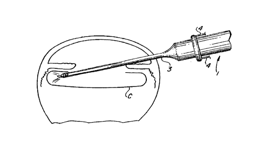
T~ILE~ ~ES~RTP'~'lON OF TIIE PI~EFERREP EMBOVIMENTS
FIG. 1 shows a human eye in the process of
undergoltlg a surgical procedure using a
phacoemulsificatioll instrumellt 1 of conventional type
with a sleeve 1~ and needle 2. 'l'he instrument 1 is
inserted througll a ~cleral flap eye incision A and into
tlle anterior chamber B.
FIG. 2 schematically represents a similar
procedure being performed with the substitution of a
fiber optic sleeve in accordance witl~ the present
ZO invention. FIG. 2 sl~ows an enlarged cross-~ectional
view of the eye. The cataract has beell removed by
conventional extracapsular ~urgical technique,
including phacoemulsification, and the posterior
cap~ule c remains ~ntact. The fiber optic ~leeve 3 i~
attached at the forefro~lt of a ~t~coemulsi~cat~on
instrument 1. Optical fiber bundles 4 are shown
extendillg ~rom tlle sleeve 3. For the application
disclosed, tlle ~iber optic sleeve 3 is utilized ~or the
purposes of endoillumination, video transmission, and
application o~ photoablatiYe laser energy to the pars
plicata of t~e ciliary body for treatment of glaucoma.
FIG. 3 is an enlarged longitudinal schematic
cross-sectional view of the present invention. The
fiber optic sleeve has a proximal (leading) end 5 and
CA 02241137 1998-06-19
WO 97/22304 PCT/US95/16936
a distal (trailing~ end 6. With continuing reference
to FIG. 3, the flber op~ic as~embly 3 cons~sts o~ an
elongated standard cannula a~aptor 7 at the distal end
6 t~lat is continuous witll a ~rustoconical nipple 8,
extendiltg to cap 9, and then to a tapered appl~cator
tip lo. ~n annular chamfer 11 and adjacent lipped
flange 12 on the inter~or sur~ace of the frustoconical
nipple 8 pQrm~t ~nsertion nl~d secur~ng of sn intern~l
coupler ill t11e chamber 13 or for receiving an O-ring
14, wllich prov~des a liquid-tight seal when the 61eeve
is assembled on tlle surgical instrument. It is
contemplated that other types of securing means such as
locking rings can ~e use~ to secure the f iber optic
sleeve member to the forefront of a surgical
ins~rument. ~ circumferential lip 27 is prov$ded at
the distal end for facilitating installation of the
sleeve 3 on a surgical il~s~rument in preparation for
use. '~~he entire longitudinal len~tll of the fiber optic
sleeve 3 i8 approxlmately one incl~.
Tlle fiber optlc sleeve 3 of the present
islvel~tioll is constructed of so~t plastic material
containing one or multiple fiber optic bundles.
~iber bundle 15 is shown in FIG. 3~ and FIG. 3B.
Material use~ in construction consists of vinyl plaqtic
or other commercially available non-toxic medical grade
plastic. ~iber optic bundle~ 15 contained within the
body o~ the sleeve are constructed of commercially
available ~uartz or zlrconium fluoride optical fibers.
'l'he size of the central cylindrical bore 16 can be
3~ controlled during tlle manu~acturing process, so that
- the fiber optic sleeve may ~e adaptable to a variety of
surgical instruments. One or two portals 29 at the
proximal end o~ the sleeve can be constructed at the
time of manu~acture to allow for ~low of fluid between
the fiber optic sleeve an~ the surgical instrument
,
CA 02241137 1998-06-19
WO 97/Z2304 PCT/US95/16936
contained in its bore. Fluid entry allows maintenance
of globe pressure and prevents excess lleating of the
laser element.
Tlle cap 9, nipple 8 an~ cannula adaptor 7 are
prefetably encased by opaque silicone,
tetrafluoretllylelle coating, or E)olyethylene cladding,
W}liC}l enhances optical transmission and also forms a
protective slleatll. The extent of cladding can be
varie~ depending on the amount and direction of light
lo transmi~sion desired: cladding tllat terminates one
millimeter from tlle proximal en~ o~ the applicator tip
10 would provide di~Euse illuminatioll, wherea~ cla~ding
to the most anterior edge of the applicator tip lo may
be de~irable in situations where a more Eocused beam is
necessary. ~r~le ~ace 18 of tlle proximal tip 10 is
unclad alld unencapsulated to provi~e uninterrupted
ap~lication or ligl~t for illumina~ion, microendoscopy,
or laser beam applicat~on.
Coupling to standard sources ~or ~ideo,
illumination or video is secured at the distal portion
of the ~iber optic sleeve 3 by ~tandard method~.
Optical fiber couplers are well kl-own in tlle prior art,
for example see patent 4,~89,5~ ~E Christopher E.
Polczyllski. In FlG. 3 a recessed, ~emale receptor well
19 at the distal face of the cannula adaptor 7 serves
to connect to an external male fiber optic cable (not
~hown~. Vetails o~ alternative embodiments are shown
in FIGS. 3~ and 3B. The embo~iment of FIG. 3A
comprises an interllally tllreaded anllular ~emale well
~0 1s~ ~aving an accurately machined surEace of revolution
to interfit with a correspon~ing threaded male
connector fiber optic source (no~ 5}10WIl) ~ The ~lat
base of tlle receptor well 19~ allows for a secure fit
and good ligl-t transmitting conllectioll between the
Eiber op~ic ~undle from the llyll~ source and the
CA 02241137 1998-06-19
WO 97/22304 PCT/US9S/16936
11
optic~l fibers 15 in the sleeve 3. 'rhe number and
placemen~ of individual optical ~ibers arranged in
receptacles in the receptor well 19 can be controlled
during Ule manufacturinq process.
~lternatively, the receptacle well of FIG. 3B
is shown as a thread~ess cone l9B having a gradual
internal taper for receiving a similarly tapered,
mating en~ of the fiber optic cable from the light
source tto nl~ annular diameter smaller than the
connectillg fiber optic ~ource]. In th~s arrangement~
a~l exterllnl fiber optic cable is precision for~ed to
mate ~nugly within the receptacle well l9B. In
nd~itioll, tlle posterior el~d G can ~e attaclle~ to a
laser catlleter assembly by means of a conventional
coupler or heat shrink wrap.
FIG. 4 shows a tangelltial cross-sectional
representatioll of the present invention. The flber
optlc sleeve 3 consists of individual tracts of f~ber
optic bun(lles 15 of 500 to G00 micron quartz fiber~
havillg a ~end radius of 4 centimeters or less that are
incorp~rated within the body of tlle sleeve 3. The
fiber optic bundles 15 Wit~ l the sleeve 3 can be
a~ranged in distinct radially-spaced coherent light
conducting portions, or in fi~er bundles havinq spatial
fiber distribution. In accor~ance with one particular
~eature of the invention, the tips of the optical
fibers witlli~l the bore of tlle sleeve are recessed
slightly ~or providing a collimated output beam. It i8
contemplated that a lens sucll as the lens 28 of FIG. 4A
3~ can be fused at the proximal eild of the fiber optic
bundle for rOcusing laser energy 30, ~r at tlle proximal
end of tlle fiber optic bundle for illumination 31, or
at tlle proximal end of the fiber optic bundle for
endoscopy 32. ~lternatively, an end piece 33 bearing
a plurality of lenses 28 for t~e respective bundles 15
CA 02241137 1998-06-lg
W097/22304 PCT~S9S/16936
at t11eir respective terminations 30, 31 and 32 can be
installed a~ tl~e elld ~ace 18 of tl-e 51eeve 3. SUch a
let~s may be mat~ufactured with a combina'tion of convex,
concave or ~lat surfaces. In tlle example of FIG. 4A,
a plano-cotlcave lens is shown.
FIG. S shows an alternative embodiment o~ the
present invet~tion con~ist~ng o~ a sleeve 3' of
opt~cally cle~r rlexible plastic 20 encased on its
outer 21 and inner 22 sur~aces by a thin layer of
lo silicone clad~ing or opaq~e, non-toxic plastic capsule
with a low index of refraction, or by a reflective
coating, SUCII as polytetrafluoretllylene, which enhances
the optical transmission of the ~iber optic sleeve. In
this embodiment, the fiber optic bundles 15 are omitted
because the entire sleeve 3' serves as an opt~cal
wavegu~de. Tlle couplers 19', of wllich two are shown,
are regularly spaced about the periphery and serve to
couple tlle ~iber optic bundles from a light source (not
shown) illtO the optically clear plastic 20 for
2U transmissioll oE ligllt to tlle tip ell~ 5. ~lternatively
a difEusing collar may be provided, interposed between
the light cable(s) and the ~leeve 3'.
Preferably, the end ~ace at the tip end 5 of
the sleeve 3' should be beveled or angled inwardly so
tllat the light emanating from tl~e end face is directed
at an angle rad~ally inward toward the centerline of
t}~e e~bodiment. Tlli8 i~ represented schematically in
the enlarged schematic view o~ ~IG. 5~ which show~ the
end o~ the sleeve 3' encompassing a needle 4 and having
a beveled end sur~ace 30 extending at an angle ~ to a
plane normal to t~le needle 4. 'l'he central axis o~ the
needle ~ is represented by the broken line 32. The
conical beam of ligh~ emanating from the beveled
sur~ace 30 i~ represented by t~le das~led lines 34, 35.
The das11ed line 3~ intersects the axis line 32 at the
-
CA 02241137 1998-06-19
wog7n2304 PCT~S95/16936
same angle a . The inner surface 22 of the sleeve 3' is
space~ ~rom the needle 4 by a dimenslon ~.
In practice, the anqle ~ is a function of the
dimensions of the needle 4 and the sleeve 3'. For a
needle ~ having a diameter o~ 1 mm and projecting from
the end 5 o~ the ~leeve 3' by 2 mm, with sleeve wall
thicknes~ equal to O. 5 mm and spacing s also e~ual to
0.5 mm, tl~e nllgle Q 5~10Ul~ ~e approximately 23 degrees.
I~ tlle spacing S is re~uced to 0.25 mm, the angle ~
lu slloul~ be slig~ltly less tllall 20 ~egrees. ~ngle a can
actually be calcula~ed ~y ~etermini~g its tangent:
i.e., tlle distance from the outer sur~ace o~ the ~leeve
3' to the centerline 32 divided by the distance from
the en~ 5 to the intersection o~ the light cone line 34
witll tlle centerline 32. In sucll an arrangement, tlle
ligllt cone illuminates tlle ~ield of view for
approxlmately 1.5 mm beyol~ tlle needle tip and
approximately .75 mm o~ t~le end o~ the nee~le 4.
FIG. 6 lllustrates an alternative embodiment
of the ~i~er optic sleeve 3" that incorporates multiple
bundle groups of optically segregated fibers for
purposes of illumination 23, laser delivery 24, and
microendoscopy 25 containe~ within the body of the
sleeve. Segregated optical fiber bundle groups are
couple~ at the distal end to convelltional delivery
systems for illumination, laser delivery and
microendoscopy for video broadcast. It will be
understood that the optical fibers in the bundle ~or
microetldoscopy must be maintained in the ~ame
o~ientation throughout their lengtll in order that the
pixel juxtAposition of t~le display will accurately
represent the optical ~ield of view. Optical
segregation is accomplisl~ed by encapsulatioll of optic
fiber bulldles by optically opaque claddlllg 26 identical
to tllat use~ Oll tlle external and internal surfaces of
CA 02241137 1998-06-19
W097/22304 PCT~S95/16936
ttle sleeve 3' in t}~e embodimellt oE FIG. 5.
ODeration in U8e.
Tlle operation o~ the 6ystem i5 as follows:
~ light cable, la~er cable or video cable
5 (not sllowll) is connected at a receptacle well 19
situated in tlle terminal rim 27 o~ the ~iber optic
sleeve 3. ~ ~iber optlc bundle ~onclucts light between
t~e attacllmellt at the receptacle well 19, througl) the
wall o~ e riber optic sleeve cn~nula 7, CAp 8, cap 9
lo and proximal face o~ the fiber optic applicator tip 10.
Flber optic ~undles 1~ terminating at the proximal ~ace
o~ the fiber opt~c sleeve 3 provide light to illuminate
the operative area of regard, or may provide laser
energy ~or treatment o~ intraocular structure~.
Separ~te and coherent fiber optic bundles 25 similarly
coursing witl~ tlle walls oE tlle fiber optic sleeve,
provi~e intraocular endoscopy. Saline ~lui~ to
maintaill glo~e pressure enters ~rom the contained
surgical instrument and travels within the hypodermic
lumen to be discharged at the open applicator tip 16 or
portals 29 Or the ~iber optic sleeve. Operation is the
same for illumination using t~le sleeve 3' o~ FIG. 5 by
coupling tlle liqht cable directly to the sleeve 3'.
~ ough there have been described
hereinabove various specific arrangemellts o~ a fiber
optic sleeve for surgical instruments in accordance
Wittl the invelltioll ~or tl~e purpose o~ illustratillg the
mallller in wl~icll tlle inventiolt may ~e use~ ~o advantage,
it will be appreciated that t~e invention is not
limited tt~ereto. ~ccordi.ngly, any and all
modi~ications, variations or equivalent arrangements
wlllcll may occur to those skilled in the art should be
con~idered to be within t~te scope of the inven~ion as
de~ined in t~le annexed claims.
CA 0224ll37 l998-06-ls
W097/22304 PCT~S9~/16936
In addition to using the ~iber optic sleeve as an
optical wave guide, as shown in FIGS. 1 - 6, optical fibers
also can be incorporated in a phacoemulsification instrument
for illumination, endoscopy and laser treatment, as shown
in FIGS. 7 - 13 to produce an obli~ue illumination of the
retina. These optical fiber components can be inserted
through a vibrating needle; along a longitudina1 axis
between the central barrel and instrument casing; centrally
into the instrument body by means o~ a connecting electrical
power cable; through fluid irrigation and aspiration
channels; through the connector coupling with the working
vibrating needle or ~iber optic sleeve; transmission through
an accessory irrigation-aspiration handpiece; and
transmission through an accessory cystotome or cannula.
Obliquelighting, providedbyopticalfibers integrated
with phacoemulsification instrumentation provides decided
advantages ~or the patient and operating surgeon. In the
present state of the art, illumination of the surgical site
is provided by direct coaxial illumination from an operating
microscope. Direct and intense light from this source i8
associated with retinal phototoxicity and impaired vision.
Thus, focal illumination from optical ~ibers integrated with
phacoemulsification instruments are directed obliquely away
from the retina, since the instruments are directed from a
side incision. Illumination provided in this manner allows
the operating surgeon to reduce the amount of direct light
necessary to perform ocular surgery, which in turn minimizes
the potential for retinal phototoxicity. In addition,
visibility of intraocular structures is enhanced. The need
for oblique lighting is further confirmed by a Public Health
Advisory issued by the Food and Drug Administration (FDA)
- on October 16, l99S and incorporated herein by reference.
CA 0224ll37 l998-06-ls
W097/22304 PCT~S95/16936
The intent of the FDA Public Health Advisory is to
remind and caution ophthalmic surgeons o~ the "...retinal
hazards from operating microscopes....and recom~n~R actions
to minimize the risk of retinal photic injury from operating
microscopes... ". The FDA Public Health Advisory recommends
that ophthalmic 6urgeons "...use oblique lighting if it is
available...to reduce risk o~ retinal photic injury."
~ence, the present invention combines a phaco-
emulsification instrument ~or cataract surgery using
integrated optical fibers to produce lighting at an oblique
angle to the retina. A suitable device ~or effecting the
objects of this invention is shown in FIG. 7. The
phacoemulsi~ication device 39 o~ this invention comprises
a hand held, elongate casing 40 defining a distal end 41 and
a proximal end 42. An inlet port 43, connecting channel 43a
and outlet port 43b enable infusion of ~luid between an
infusion sleeve and a working, vibrating needle to
intraocular structures during surgery.
Mounted within the casing 40 is an acoustic transformer
comprising a coupling member 44 bolted to the casing and
connected or abuttiny a metallic coupling 45 such as
stainless steel or titanium. Elastomeric 0-rings 46, 47
~orm a water tight seal between the coupling member 44 and
the casing 40 during fluid infusion through inlet port 43.
A magnetostrictive orpiezoelectric transducer 50 is mounted
on the metallic coupling 45 and is actuated by current
through an electric coil 51 which is supplied by current
through a power cable 52 secured in distal end 41.
Actuation of the transducer produces high ~requency
longitudinal vibrations which are transmitted to a hollow,
titanium, plastic or ceramic needle 48 de~ining a working
needle tip 48a and a needle base 48b, the needle being
threadably mounted on the metallic coupling 45. Vibration
o~ the hollow needle di6integrates ti6sue which contacts the
working needle tip.
CA 02241137 1998-06-19
W097/22304 PCT~S95/16936
A coincident aspiration channel 53 extends from the
channels 54 and 55 of the coupling member 44 and the
- metallic coupling 45, respectively. Tissue disintegrated
by the working needle tip ~8a at the surgical site is
removed by aspiration through the needle 48 to the
aspiration channel 53 using suction means (not shown)
provided at the distal end 41 o~ the device 39.
A protective, non-toxic plastic infusion sleeve 57 for
the needle 48 i9 mounted on the casing 40, and an annular
space 58 is formed between the sleeve and the needle. Fluid
infusion from the inlet port 43 passes through the annu~ar
space 58 to irrigate the surgery site and cool the vibrating
needle. The working needle tip 48a extends slightly beyond
the end o~ the infusion sleeve.
In one e~bodiment of the invention, a fiber optic
bundle 60 containing one or more fiber optic lines enters
the device 39 from its distal end, preferably in combination
with the power cable 52. Alternatively, the fiber optic
bundle 60 may be isolated from the power cable and enters
the device at a separate port located at the distal end of
the device. Also, the fiber optic bundle and electric power
cable may supplied either by a common line or by separate
lines into a single unit 61. The fiber optic bundle is
threaded axially along the device, through the coupling 44
where it is secured, into the aspiration channel 53 at an
angled inlet 63 adjacent to the base 48b of the needle 48,
where it terminates. ~ather than terminating at base 48b
of the needle, the fiber optic bundle may extend partially
or entirely through the needle. Alternatively, the proximal
end of fiber optic bundle 60 may be coupled by standard
means to the infusion sleeve 57 functioning as an optical
wave guide, similar to FI~. 4. The aspiration channel 53
and inner surface of the needle may be machine polished or
coated with a reflective coating such as TEFLON to enhance
optical transmission.
CA 0224ll37 l998-06-ls
W097/22304 PCT~S95/16936
18
Typically, the fiber optic bundle is encased in a
protective jacket, and the surface of the jacket may be
roughened or configured with protuberances to contact the
inside wall of the casing 40 and minimize movement of the
fiber optic bundle. If desired, the fiber optic bundle can
be coated by a reflective material such as polyethylene,
silicone, polytetrafluoroethylene (TEFLON), or a ceramic,
to enhance reflectivity. A cone of light is formed at the
proximal end of the fiber optic bundle which obliquely
illuminates the retina similarly to FIG. 5A.
FIG. 8 is a schematic view of a fiber optic bundle fed
through a central aspiration channel in addition to a fiber
optic bundle on each side of the aspiration channel. The
transducer components have been omitted for clarity.
The phacoemulsification device 63 in FIG. 8 provides
a hand held, elongate, outer casing 64, infusion channel 65,
aspiration channel 67, a hollow needle element 68
terminating the end of the channel 67, outer fiber optic
lines 69 and 70 mounted within the outer casing 64, and a
central fiber optic line 71 leading through the central
aspiration channel 67. The fiber optic lines 69 and 70 are
supplied by an Injection Laser Diode (I~D) source 72 or
Light Emitting Diodes (LED), mounted within the device, and
powered through a cable 73 ~rom an external power supply
(not shown). Alternatively, the fiber optic lines 69, 70
may be supplied by an external source o~ light (not shown).
The proximal ends of the fiber optic lines terminate in
standard fiber optic couplers ~uch as ferrules which are
manufactured by AMP. Suitable materials ~or ferrules
include plastic, stainless steel metal, and ceramics such
as alumina oxide or zirconia oxide.
CA 02241137 1998-06-19
W097/22304 PCT~S95/16936
A Y-shaped plastic adaptor 75 ~which may be disposable)
is mounted at the distal end of the aspiration channel 67,
~ one branch 76 of the adaptor being supplied with a fiber
optic bundle which leads through the central fiber optic
line 71, and the other branch 77 of the adaptor being used
to aspirate fluid and tissue remnants. The bore size of the
aspiration channel 67 can be controlled during manufacturing
so that it may accommodate a wide variety of ~iber optic
bundle sizes.
Alternatively, the fiber optic bundle can be supported
by a fenestrated spoke wheel 80, as shown in FIG. 8a. A
rim portion 81 mounts a plurality of spokes 82 which
terminate in an annular hub 83 through which are threaded
~iber optic bundles. The rim portion 81 of the spo~e wheel
functions as a supporting strut secured along the inside
wall of the aspiration channel. The fiber optic bundles can
extend for a variable length through the aspiration channel
as a free floating member, and the number of spoke wheels
employed depends on the extension length o~ the ~iber optic
bundles within the channel.
FIG. 9 shows an alternative embodiment of a phaco-
emulsification device 90, the transducer components being
omitted for purposes of simplification. The device 90
comprises a hand held, elongate casing 9l, a central
aspirating channel 92, an infusion channel 93, and a hollow
needle 94 mounted at the end of the aspirating channel. A
light source for the device 90 is threaded through the
distal end of the device and can be diverted into a
plurality of isolated fiber optic bundles by means o~ a
standard fiber optic star, or tree coupler 95. A plurality
of optic bundles, two bundles 96, 97 being shown, are
mounted within the casing 9l and terminate in connecting
ferrules 98 and 99, respectively.
CA 02241137 1998-06-19
W097/22304 PCT~S95/16936
In addition to using fiber optic illumination by means
of a phacoemulsification device illustrated in FIGS. 7 - 9,
to produce oblique illumination, fiber optic bundles can be
integrated with accessory cataract surgery instruments, as
shown in FIGS. l0 - 13. FIG. l0 shows an irrigation-
aspiration hand piece used for removal o~ cortical cataract
remnants following removal of the cataract nucleus by
phacoemulsification. The irrigation and aspiration tubing
lines are connected to the irrigation-aspiration handpiece.
Typical devices, one of which is shown in FIG. lO are
sold by Alcon Surgical having trademark names SERIES 8000
I/A HANDPIECE and ULTR~FLOW I/A HANDPIECE. These Alcon
Surgical products are described in their brochure numbered
905-2000-502, which is incorporated herein, by reference.
In FIG. lO, a hollow, cataract surgical handpiece lO0
(SERIES 8000 l/A HANDPIECE~ with channels for aspiration and
irrigation provides a distal end l0l with ports 102 and 103
which connect with non-toxic plastic tubing to an irrigation
fluid supply and a fluid aspiration pump (not illustrated)
shown in the directions of the arrows. The proximal end 104
of the hand piece mounts an irrigation-aspiration tip 105
connected to the handpiece l00 at its base 106. The tip
is used to remove cataract remnants by aspiration while
maintaining intraocular pressure by irrigation. Fiber optic
bundles are mounted through the irrigation supply port 102
and through the core of the handpiece body, Alternatively,
the optic bundles may be mounted through the open distal end
l0l. As shown in the enlargement of FIG. l0a, a plurality
o~ fiber optic bundles, two bundles 107 and 108 being shown,
are mounted along the periphery of the base 106. Optic
fiber couplers l09 and ll0 connect the proximal ends of the
~iber optic bundles to a light transmitting plastic infusion
sleeve (not shown~ similarly to the preceding examples.
CA 0224ll37 l998-06-ls
WO 97/22304 PCTIUS9S/16936
FIG. 11 illustrates a view of a hollow, cataract
surgical hand piece 115 for supplying irrigation only, and
onto which is mounted a cystotome 116 constructed of a light
conducting material such as a plastic or a ceramic. This
hand piece i8 used by the surgeon to per~orm an anterior
capsulotomy after the entry incision is constructed. The
irrigation hand piece i8 utilized to control the cystotome
and deliver fluid to maintain intraocular pressure.
Fiber optic bundles, two bundles ll9, 120 being shown,
are incorporated in the irrigation hand piece in a similar
manner to the irrigation-aspiration hand piece previously
described. The fiber optic bundle~3 terminate at the
proximal tip 118 of the handpiece to couple with the plastic
cystotome 116 and obliquely illuminate the retina. In this
embodiment, optical fiber couplers 121 and 122 connect to
recessed female receptor wells (not shown) at the distal
face of the cystotome.
FIG. 12 illustrates a hollow, irrigation handpiece 130
of the same type as the hand piece 115 for supplying
irrigation only, and to which is attached an irrigating
scraping tip 131 that i~ similarly constructed o~ a light
conducting material such as a plastic or ceramic. This
instrument is used to polish the anterior surface oE the
posterior lens capsule. The distal end base 132 of the
scraping tip 131 is connected to a plurality o~ fiber optic
bundles, two bundles 133 and 134 being shown. Optical fiber
couplers 135 and 136 function to transmit light to the
irrigating scraping tip 131.
CA 0224ll37 l998-06-ls
W097/22304 PCT~S95/16936
FIG. 13 illustrates a hollow, irrigating handpiece 140
similar to the hand pieces 115 and 130, and similarly
constructed, and to which is attached a cyclodialysis
cannula 141. The cyclodialysis cannula is used by the
operating surgeon to sever intraocular tissue adhesions and
manipulate the position of the intraocular lens. The distal
end base 142 of the cannula is connected to a plurality of
fiber optic bundles, two bundles 143 and 144 being shown.
Optical couplers 145 and 146 connect the fiber optic bundles
1~ to the distal end of the cyclodialysis cannula.
It will be appreciated that a fiber optic bundle can
extend either partly or completely through the accessory
instruments 116, 131 and 141, instead of terminating at
their respective bases, to produce oblique illumination of
the retina.