Note: Descriptions are shown in the official language in which they were submitted.
CA 02241409 1998-06-2~
WO 97/27636 PCTrUS96/11741
MATERIAL AND METHOD FOR LOW
INTERNAL RESISTANCE LI-ION B~TTERY
BACKGROUND QF THE T~VENTION
The present invention relates to secondary, rechargeable
batteries, particularly such batteries which are constructed of
layered, polymeric composition electrode and electrolyte
elements laminated with electrically-conductive collector
members, typically metallic foils. More particularly, the
invention relates to such batteries comprising reticulate
collector foils and provides a means for reducing the internal
electrical resistance factor of such batteries which may, in
part, be attributable to insulating metallic oxides formed on
the surface of such collector ~oils, as well as the insulating
effect of electrolyte solution wetting the electrode/collector
foil inter~ace
Typical laminated polymeric composition battery
structures with which the present invention is useful are
described, for example, in U.S. Patents 5,46G,904 and
5,478,668. Such a battery comprises respective positive and
negative polymeric matrix electrode composition layers of
lithium intercalation compound and carbon which are laminated
together and to metal foil current collector elements that
provide the primary terminals for electrical connections.
CA 0224l409 l998-06-2~
W097/27636 PCT~US96/11741
As is known in the industry, the individual electrical
resistance of each member of a battery structure contributes to
an overall internal battery resistance which represents a non-
productive load and energy drain in any utilization circuit,
particularly one which includes an external low impedance
device. The power dissipated in overcoming such internal
resistance not only detracts directly ~rom the ef~iciency o~ a
battery, it may ~urther generate within the battery a level of
heat which has a deleterious e~ect on not only the operation of
the battery, but also on the integrity of the battery members,
viz., the electrodes and electrolyte. ~uch e~fects are
particularly ~elt by polymeric members of the noted laminated
lithium ion rechargeable batteries.
A signi~icant source of electrical resistance has been
observed in the oxide which readily forms on the sur~ace of the
current collector foils, particularly aluminum, preferably
employed with the polymer matrix lithium intercalation compound
and carbon electrode compositions o~ battery cells such as
described in the above-noted patents. Also contributing to the
resistance in these cells has been the introduction of
activating electrolyte solution which results in a swelling and
expansion o~ the electrode members and intrusion of the
solution between the electrode and collector surfaces, thereby
inter~ering with the firm physical contact which ensures good
electrical conductivity through these members.
The present invention provides an effective means of
substantially eliminating the formation o~ insulating metal
oxides on the collector elements, as well as of maint~; n; ng the
integrity of a strong physical, electrically-conductive bond
CA 02241409 1998-06-2~
W 097/27636 PCTrUS96/11741
between the electrode and collector members, and thereby
dramatically reducing the internal resistance o~ the Li-ion
intercalation battery cells which are gaining ~avor in the
industry.
SUMMARY OF T~ INVENTION
In the implementation o~ the present invention, metal
collector elements, typically o~ copper and aluminum ~oil and
pre~erably in the ~orm o~ open-mesh grids, are surface-treated
with solvent and etching solution to remove processing oils and
metallic oxides ~ormed during manu~acture. Therea~ter, the
collector foil sur~aces are coated with a protective, metal-
adherent, non-swelling polymeric composition comprising a
homogeneously dispersed electrically-conductive material, such
as carbon black, which serves to maintain the electrical
conductivity between the coated collector member and its
associated polymer-based electrode.
The polymer o~ the coating composition may be any
material which is substantially insoluble in and pre~erably not
wetted or swollen by the solvents, such as ethers, esters, or
alcohols, used to extract the plasticizer, e.g., DBP, from the
battery cell electrode and separator members, and the lithium
salt solvents, such as the cyclic and acyclic carbonates,
comprising activating electrolyte solutions. Polyole~in-based
compositions, such as poly (ethylene-co-acrylic acid)
copolymers serve well in this role. Such a selected polymer
matrix not only provides a strongly-adherent protective ~ilm
CA 02241409 1998-06-2~
W097/27636 PCTrUS96/11741
which deters subse~uent oxidation, but also resists degradation
of conductive continuity upon contact by subse~uently-applied
processing solvents and electrolyte solutions.
~RIEF DESCRIPTIQN OF THE D ~ WING
The present invention will be described with reference to
10 ~ the accompanying drawing of which:
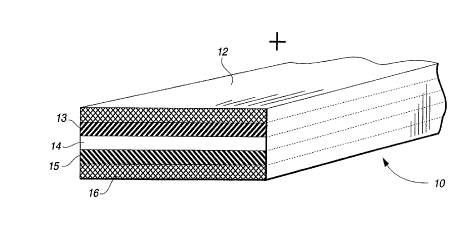
FIG. 1 iS a perspective view of a representative section
of a typical polymeric laminated battery structure;
FIG. 2 is a plan view of a section o~ a current collector
grid member used in the battery structure of FIG. l;
FIG. 3 iS a cut-away elevational view of the current
collector member section of FIG. 2 taken along line 4-4 showing
the protective collector coating of the present invention;
FIG. 4 is a representation, in elevational section, of a
typical polymeric laminated battery structure showing
variations in disposition of the coated collector member within
2 5 the structure; and
FIG. 5 presents comparative charge/discharge cycle traces
of Li-ion cells comprising collector members with and without
treatment according to the present invention.
CA 02241409 1998-06-2~
W097/27636 PCTrUS96/11741
DESCRIPTION OF THE TNV~.NTION
The structure of a representative polymer-based Li-ion
battery may be seen in the model of FIG. 1 as comprising a
unitary laminate of a positive electrode composition layer 13
with its associated current collector member 12, an
intermediate separator/electrolyte layer 14, and a negative
electrode composition layer 15 with its associated current
collector member 16. When initially assembled for lamination,
the structure components typically include: as electrode 13, a
300 ~m thick film of 56 parts by weight of a LiMn204
intercalation compound and 6 parts of carbon black intimately
dispersed in a binder matrix of 16 parts of an 88:12 vinylidene
fluoride:hexafluoropropylene (PVdF:HFP) copolymer plasticized
with 16 parts of dibutylphthalate (DBP); as separator 14, an 85
~m thick film of 20 parts of colloidal silica intimately
dispersed in 30 parts of the copolymer plasticized with 50 parts
of DBP; and as electrode 15, a 200 ~m thick film of 56 parts of
microbead coke and 3 parts of carbon black intimately dispersed
in 15 parts of the copolymer plasticized with 23 parts of DBP.
Since, as described in the above-noted patents, the post-
lamination processing of the battery structure will include a
solvent extraction of the DBP plasticizer from the polymer
matrices, one or both, as depicted in FIG. 1, of copper
collector ~oil 16 and aluminum collector ~oil 12 may be
reticulate, for example in the form of a 50 ~m thick expanded
metal grid, such as the Micro~rid precision foil marketed by
Delker Corporation, in order to provide suitable pathways for
solvent penetration.
CA 02241409 1998-06-2~
WO 97/27636 PCT~US96/11741
In representative examples of a preferred embodiment of
the present invention, respective sections of copper and
aluminum expanded foil grid 20 (FIG. 2) were coated with a
conductive composition of commercial grade conductive battery
carbon black, such as MMM Super P, dispersed in a commercially-
available aqueous suspension o~ a copolymer of polyethylene
with acrylic acid, e.g., Morton International Adcote primer
50C12. The resulting current collector material comprised, as
depicted in FIG. 3, the metal grid substrate 23 encompassed in
about a 1-5 ~m thick layer of conductive composition 34.
Example 1
A typical coating composition was prepared by dispersing
in a ball mill for about 1 h at room temperature about 5 parts
by weight of carbon black, about 100 parts of about a 12%
copolymer suspension, and about 100 parts of ethanol. The
dispersion was then thinned with about an equal part o~ ethanol
to provide a convenient viscosity for dip- or spray-coating the
grid substrate which ensured retention of the open areas 25 in
the grid. Prior to spraying portions of grid substrates with the
coating composition, oils and oxides were removed from the foil
surfaces with an acetone rinse and, for the aluminum grid, about
a 50 s dip in a 1 N aqueous solution of KOH or NaOH, followed by
water and acetone rinses and drying. The conductive coating
composition was then applied, and the coated grid material was
dried in air at room temperature. The amount of carbon has been
~ound to be use~ul in a range of about 5-50% by weight of the
dried coating, pre~erably about 30%.
.
CA 02241409 1998-06-2~
W 097/27636 PCTAJS96/11741
As a measure of the improvement in the resistance
achieved by this treatment according to the invention, pairs of
160 mm2 sections of treated and untreated copper grid were
laminated to respective portions of about 180 ~m thick films of
the above coke electrode composition to form simple test cells.
These cells were then tested for transverse electrical
resistance at various stages representative of the processing
of an actual battery cell. As initially prepared, the
comparative resistances of the treated:untreated collector
10 cells were 0.26Q:0.6Q. After methanol extraction of the DBP
plasticizer, the cells tested at 0.15Q:0.5Q. Finally, after the
cells were immersed in 1 M LiPF6/EC/DMC electrolyte solution to
substantially saturate the electrode composition, the tests
indicated resistances of 0.20Q:6.0Q. Similar test cells were
prepared of aluminum grid and films of LiMn2O4 electrode
composition. The staged resistance tests of the treated:
untreated cells yielded results of l.OQ:1.57Q, 0.72Q:0.65Q,
and 0.83Q:14.0Q.
Example 2
~he coated collector ~rid materials of Example 1 were
assembled with previously-described electrode and separator
members 13, 14, 15 to fabricate battery cell laminates, such as
25 depicted at 10 and 40 (FIG.4). Due to the high level of
electrical conductivity exhibited by the coated collector
members, they may be respectively situated at any desired
location in the cell structure. For example, each collector
member may be overlaid upon its respective electrode film or
layer, as shown in FIG. 1, to be laminated with and, if in grid
form, embedded to any desired depth in its associated electrode
CA 02241409 1998-06-2~
W 097/27636 PCTrUS96111741 ___
upon the application o~ ~abrication heat and pressure.
Alternatively, as depicted in FIG. 4, to achieve ~urther
improvement in the reduction of internal cell resistance a
coated grid collector member 41 may be laminated between
-sections of electrode material 43 in order to be situated wholly
within the electrode, or a grid collector member 49 may be
assembled at the interface between its associated electrode 47
and separator member 45. In such latter embodiments, it is
convenient to allow for an extended collector grid tab, as at 42
or 48, in order to provide an accessible cell t~rm;n~l.
After lamination, a completed battery cell as represented
in FIG. 1 was processed as descri~ed in the noted patents by
immersion in methanol to extract substantially all the DBP
plasticizer from the electrode and separator matrix
compositions. Ready access of the extracting solvent to these
members is ensured by the retained grid openings in at least one
of the collector members. Subsequent activation of the cell, in
the described manner, by immersion in an electrolyte solution
of 1 M LiPF6 in an equipart mixture of ethylene carbonate (EC)
and dimethyl carbonate (DMC) prepared the cell for charge/
discharge cycling. The cell exhibited remarkably good internal
=resistance of about 50-150 mQ/Ah capacity.
Example 3
In a comparative example to quantify the efficacy of the
collector coating compositions of the invention, a similar cell
was prepared in the manner described in U.S Patent 5,470,357,
that is, the collector grid elements were pretreated with a
thin, post-heated prime coat of the PVdF:HFP electrode matrix
CA 02241409 1998-06-2
W 097/27636 PCTrUS96/11741
polymer to enhance lamination adhesion between the electrode
and collector members. After extraction and activation with
electrolyte solution, the cell exhibited an internal resistance
of about 600-2000 mQ/Ah capacity. Apparently, the normally
employed solvents and electrolyte solutions whose functionality
depends upon their swelling and penetrating the electrode and
separator copolymer matrices also penetrated the collector
element primer coatings and degraded the electrical continuity
between the electrodes and the collector foil surfaces and
contributed to the increased internal resistance. These results
indicate the advantage achieved from the use of the pre~erred
collector coating composition polymers which are substantially
inert to the cell-processing solvents.
Further indicative of the efficacy of the collector
element treatment of the present invention are the comparative
cycling traces of FIG. 5 which evidence the lesser degree o~
available charging, represented by less deintercalation of
lithium ions, in the untreated sample prior to charging current
cut-off at 4.5 V, as well as the lower level of productive
voltage output under the same constant current load.
It is anticipated that numerous other implementations of
the described manner of effecting improved internal cell
resistance will occur to the skilled artisan, and such variants
are nonetheless intended to be within the scope of the present
invention as de~ined in the appended claims.
_ g _