Note: Descriptions are shown in the official language in which they were submitted.
CA 02241490 1998-06-25
IMPROVED PNEUMATIC TUBE SYSTEM CARRIER
FIELD OF THE INVENTION
The present invention generally relates to carriers for use in pneumatic tube
transport
systems, and, in particular, to seal bands for carriers which can be used in
pneumatic tube
transport systems.
BACKGROUND OF THE INVENTION
Generally, pneumatic tube transport systems are used to transport or convey
materials
between discrete points or stations. Many products, documents and other items
may be
placed in a carrier which is positionable within a number of substantially
hermetically sealed
tubes of the pneumatic tube transport system. The carrier may then be
propelled through the
tube by creating a zone of relatively higher pressure behind the carrier than
in front of the
carrier. This pressure differential may be accomplished by creating a vacuum
or zone of
negative pressure in front of the carrier or by creating a zone of positive
pressure behind the
carrier.
Accelerator rings or seal bands have been provided on carriers to prevent
excessive
mass transfer of air between the front of the carrier and the rear of the
carrier. Such seal
bands thus create differential pressure between the front and rear portions of
a carrier, which
provides the force necessary to propel the carrier through the pneumatic tube
system. Such
accelerator rings or seal bands typically engage the inner surface of the
transport tube to
support the carrier body and to inhibit air flow between the front and rear
portions of the
carrier. In this regaxd, it is important to minimize friction between the seal
bands and the
inner wall of the tube to enable the carrier to move through the tube without
requiring high
differential pressures between the front and rear of the carrier. Such a
desire for minimizing
friction must also be balanced with providing an adequate seal to inhibit mass
transfer of air
between the front and the rear of the Garners. In this regard, a "loose" seal
band which does
not provide a good seal may travel freely, but may also perform erratically
for varying
payloads within the carrier. On the other hand, while a "tight" seal will
inhibit mass transfer
of air between the front and rear portions of the carrier, friction forces
between the seal band
and tube may be high, thus requiring increased system pressures of the
transport tube. Such
tight seals may also generate an excessive amount of debris from wear on the
seal bands,
which can degrade performance of the tube transport system and/or components,
such as
blowers and optical sensors therein.
CA 02241490 2003-11-28
SUMMARY OF THE INVENTION
Accordingly, it is an object of the present invention to provide a carrier
having a seal
band which provides a sufficient seal to create an effective pressure
differential between the
front and rear portions of the carrier, the carrier for use in a pneumatic
tube transport system.
It is another object of the present invention to provide a carrier having a
seal band
which generates low friction forces to enable the carrier to move efficiently
through a
transport tube of a pneumatic tube transport system.
It is a further object of the present invention to provide a carrier for use
in a
pneumatic tube transport system, the earner having a seal band which does not
wear unevenly
and which does not result in an excessive amount of contaminants.
The present invention accomplishes one or more of these objectives by
providing a
carrier having an improved seal band. Generally, the carrier includes
generally cylindrical
first and second shell members, a hinge means interconnectable to the first
and second shell
members for moving the first and second shell members relative to each other
between open
and closed positions, and at least a first seal band interconnected to at
least one of the fore
and aft portions of the first and second shell members, about at least a
portion of the
circumference of the first and second shell members. The first seal band
supports the first
and second shell members and minimizes fluid flow in at least a first tube of
a pneumatic
tube transport system from the fore portion to the aft portion of the first
and second shell
members to move the earner through the first tube. The first seal band
includes a plurality of singular, stiff but bendable fibers mountable in a
first backing strip,
the plurality of fibers preferably having a modulus of elasticity of at least
1 X 10⁵ pounds per
square inch (psi). Advantageously, such fibers tend to remain substantially
straight or erect,
and do not flatten out after a period of extended use. In this regard, the
fibers reduce wear
and tear on the carrier, including the backing strip, and on the tube system
as the singular,
erect fibers do not tend to catch or snag upon tube joints or other
protrusions within the tubes,
even after prolonged use.
Such fibers generally have first and second end portions, the first end
portions for
fractionally engaging the inner wall of at least the first tube at a plurality
of contact points,
and the second end portions being mountable in the first backing strip, which
is
interconnectable to at least one of the first and second shell members. In
this regard, the
carrier and contents contained therein are supported by a plurality of stiff,
yet bendable, erect
fibers which are fractionally engageable with the inner wall of at least the
first tube of the
pneumatic tube transport system to support the first and second shell, as well
as the contents
2
CA 02241490 1998-06-25
contained therein, and to provide a sufficient seal to minimize mass flow of
air from the rear
of the carrier to the front of the carrier, which provides the motive force to
move the carrier
through at least the first tube of the pneumatic tube transport system. In
addition, the
plurality of fibers enhances transport efficiency (e.g., the ride) of a
carrier through tubes of
a pneumatic tube system and, in particular, over imperfections in a tube wall
and/or joints
between adjoining tubes, and since the fibers are stiff, yet bendable, which
results in a
smoother ride for the contents of the carrier (e.g., less impact forces or
shock translated to the
contents of the carrier).
In one embodiment of the seal bands of the present invention, the plurality of
fibers
of at least a first seal band are densely packed and uniformly distributed
over the first backing
strip. Such packing density and distribution provides multiple contact points
with the inner
wall of at least the first tube for inhibiting mass transfer of air between
the fore and aft
portions of the carrier, which creates an effective pressure differential
between the fore and
aft portions of the carrier to move the carrier through the tubes of the
pneumatic tube
transport system. Further, such packing density and uniform distribution of
the plurality of
fibers supporting the first and second shells and payload contained therein
provides for a
substantially even distribution of loading of the plurality of fibers. In this
regard, due to the
high packing density of fibers per square inch on the first backing strip and
the uniform
distribution of the fibers on the first backing strip, each of the plurality
of fibers is
substantially equally loaded. As a result, the plurality of fibers of the seal
bands of the
present invention tend to last longer than prior seal bands and tend to wear
evenly. In one
embodiment, the plurality of fibers have a diameter of less than about 0.010
inches, and, in
a preferred embodiment, have a diameter of between about 0.003 inches and
about 0.005
inches. Such fibers may be mounted on the first backing strip at a packing
density of at least
about 4000 fibers per square inch, and more preferably, at least about 10,000
fibers per
square inch, and, in a preferred embodiment, between about 20,000 fibers per
square inch and
about 100,000 fibers per square inch. In such embodiments, the loading of
individual fibers
on the first backing strip is preferably below the critical buckling value.
For purposes of further enhancing support and minimizing mass transfer of
fluid flow
between the fore and aft portions of the carrier of the present invention,
each of the plurality
of fibers of the seal bands may be oriented between about 60 ° and
about 90 ° relative to the
first backing strip, and preferably substantially perpendicular relative to
the first backing
strip. In this regard, the plurality of fibers may be individually potted or
otherwise
interconnected (e.g., fastened or adhesively attached) to the first backing
strip at a selected
3
CA 02241490 2003-11-28
orientation (e.g., about 60° to about 90°) relative to the first
backing strip. Alternatively, the
plurality of fibers may be interconnected to the first backing strip in a
brush-like manner (e.g.,
in clumps or bunches) for ease of manufacturing, the fibers in a selected
clump being oriented
between about 60° and about 90° relative to the first backing
strip. Further, the fibers may
have a substantially equal height from fiber to fiber, such that the first end
portions of the
plurality of fibers may substantially uniformly contact the inner wall of at
least the first tube
of a pneumatic tube transport system. In one embodiment, at least a first of
the plurality of
fibers has a length which is within about 0.1 inch, and more preferably,
within about 0.01
inch of the length of a second of the plurality of fibers, and, in a preferred
embodiment,
within about 0.001 inch. For purposes of adequately supporting the shell
members and
contents enclosed therein, the fibers may have a length of less than about 0.5
inch, and
preferably, less than about 0.3 inch, with a slenderness ratio, as defined by
the ratio of the
length of each fiber to the radius of gyration of each fiber, of less than
about 300, and
preferably, less than about 200.
In order to achieve the above-described advantages while providing a seal band
which
does not wear (e.g., shorten) as quickly as other seal bands, the fibers
utilized in the present
invention may be made from a synthetic or metallic material. Suitable fiber
materials include
synthetics, ceramics, metals and any other material which can be made into
short, thin fibers
and which can be mounted to a backing strip or substrate. In one embodiment,
each of the
plurality of fibers comprise single strands fabricated from abrasive silicon
carbide, abrasive
aluminum oxide, solid nylon, hollow nylon, polypropylene, short trim
polypropylene,
polyurethane, organics, steel, aluminum or other comparable metals and
synthetics which
be shaped into relatively stiff fibers having the above-summarized lengths and
diameters.
Fibers fabricated from such materials are relatively durable. As such, the
fibers do not
produce an excessive amount of contaminants, which can effect the efficiency
of the tube
system and/or components therein. These fibers may be adhesively or
mechanically attached
to the first backing strip, which may be fabricated from synthetics, metals,
organics or any
other material which is capable of structurally supporting a plurality of
densely packed fibers
and which is capable of being mounted to a cylindrical surface. As such, the
material for at
least the first backing strip may be flexible or workable to a circular
configuration.
4
CA 02241490 2003-11-28
Broadly stated, the invention is concerned with a carrier for use in a tube
transport
system comprising a first tube, said carrier comprising a containment vessel
which defines an
enclosed space and which comprises a first access to said enclosed space; at
least one seal
band interconnected with an outer surface of said containment vessel and
encircling said
containment vessel, wherein said at least one seal band comprises a plurality
of fibers; and a
first interface between any of said plurality of fibers which contact an inner
surface of said
first tube when said containment vessel is disposed in said first tube,
wherein each said first
interface consists essentially of a point contact, wherein said plurality of
fibers of said least
one seal band maintains at least an adjacent portion of said containment
vessel in spaced
relation to said inner surface of said first tube and supports said adjacent
portion of said
containment vessel within sad first tube, wherein said containment vessel is
supported within
said first tube solely by said plurality of fibers, and wherein a density of
said plurality of
fibers on said at least one seal band provides sufficient resistance to fluid
flow through said
plurality of fibers so as to advance said containment vessel through said
first tube when said
fluid flow is directed through said first tube.
DESCRIPTION OF THE DRAWINGS
Fig. 1 illustrates a side view of a carrier of the present invention;
4a
CA 02241490 1998-06-25
Fig. 2 illustrates a perspective view of the carrier illustrated in Fig. 1, in
an open
configuration;
Fig. 3 is a cross-sectional view of the Garner illustrated in Fig. 1, taken
along line 3-3;
Fig. 4 is a perspective, partially cut-away view of the carrier of the present
invention
positioned within a first tube of a pneumatic tube transport system;
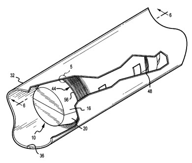
Fig. 5 is an enlarged, end view of the seal band illustrated in Fig. 4;
Fig. 6 is a cross-sectional view of the carrier of the present invention
positioned
within the first tube of the pneumatic tube transport system, taken along line
6-6; and
Fig. 7 is an enlarged, side view of the fibers of the seal band illustrated in
Fig. 6.
DETAILED DESCRIPTION OF THE INVENTION
Figs. 1-7 illustrate the various features of the carrier of the present
invention.
Generally, as illustrated in Figs. 1-2, the carrier 10 of the present
invention includes first and
second shell members 16, 20, which are cylindrical in cross-section for use in
a
correspondingly cylindrical tube transport system. The first and second shell
members 16,
are pivotally interconnected to each other via hinges 24. Such hinges 24 allow
the first
and second shell members 16, 20 to pivot relative to each other to move the
first and second
shell members 16, 20 between closed and opened positions, substantially as
shown in Figs.
1-2. In this regard, and as illustrated in Fig. 2, the first and second shell
members 16, 20 are
20 movable relative to each other to an open configuration of the carrier 10,
such that an obj ect
(not shown) can be positioned within the first and/or second shell member 16,
20 for delivery
to another destination in the pneumatic tube transport system or retrieved
upon reaching such
destination. The first and second shell members 16, 20 are also movable
relative to each
other to a closed configuration to contain the object to be transported
therebetween. The
carrier 10 also includes latches 28 for securing the first shell member 16 to
the second shell
member 20 in the closed configuration, illustrated in Fig. 1. As such, an
object contained
within the carrier 10 may be transported upon closing and securing of the
first shell 16 to the
second shell 20. In this embodiment, the carrier 10, formed by the first and
second shell
members 16, 20, provides a substantially cylindrical carrier 10 for use in a
pneumatic tube
transport system having a plurality of cylindrical tubes.
For purposes of supporting the first and second shell members 16, 20 and any
payload
enclosed therebetween within a first tube 32 of a pneumatic tube transport
system and for
creating a motive force to move or propel the carrier 10 within the first tube
32 having inner
and outer walls 36, 40, the first tube 32 being in fluid connection with a
blower (not shown)
5
CA 02241490 1998-06-25
of the pneumatic tube transport system, the carrier 10 further includes fore
and aft seal bands
44, 48, illustrated in Figs. 1-7. In accordance with the present invention,
the seal bands 44,
48 are positionable on the first and second shell members 16, 20 at forward
and rear portions
thereof, about the circumference of the first and second shell members 16, 20.
In accordance
with the present invention, the first and second seal bands 44, 48 each
include a plurality of
stiff fibers 50 which are mounted on a rigid, but flexible backing strip 56.
Further, in one embodiment, each of the fibers 50 are mounted in the backing
strip
56 such that each of the plurality of fibers 50 are perpendicular relative to
a top surface 60
of the backing strip 56. In this regard, the plurality of fibers 50 are
oriented parallel to each
other. Further, for purposes of supporting the first and second shells 16, 20
and payloads
contained therein while minimizing mass transfer between the fore and aft
portions of the
carrier 10, the plurality of fibers 50 are densely packed on the backing strip
56. In one
embodiment, the first and second seal bands have a packing density of fibers
50 on the
backing strip 56 of at least about 4000 fibers per square inch, or, more
preferably, at least
about 10,000 fibers per square inch, or, in a preferred embodiment, between
about 20,000
fibers per square inch and about 100,000 fibers per square inch, the fibers 50
having a
diameter of less than about 0.010 inch or, in a preferred embodiment, between
about 0.003
inch and about 0.005 inch. While the fiber density, as defined by the amount
of fibers
mounted on the backing strip 56 per square inch, does not provide an air-tight
seal
thereacross, the plurality of fibers 50 nevertheless provides sufficient flow
resistance to create
an effective pressure differential between the front portion of the carrier
and the rear portion
of the carrier 10.
Furthermore, the plurality of fibers 50 of the present invention are of
substantially
uniform height and are evenly distributed over the top surface 60 of the
backing strip 56.
Such uniformity in height and distribution of fibers 50 provides multiple
contact points for
supporting the carrier 10 and contents therein while traveling through the
tube 32. More
specifically, due to the uniform height and distribution of the plurality of
fibers 50, each fiber
is substantially equally loaded, as illustrated in Figs. 5-7. As such, the
seal bands 44, 48 do
not wear unevenly and thus, seal performance is not prohibitively degraded
over time and
use. In one embodiment, where the diameter of each fiber is less than about
0.010 inches,
and more preferably, between about 0.003 inches and 0.005 inches, each fiber
50 has a height
of less than about 1 inch, and more preferably, less than about 0.5 inch. In
addition, the
height of at least a first of the plurality of fibers 50 is within about 0.1
inch, and more
6
CA 02241490 1998-06-25
preferably, within about 0.01 inch, and even more preferably, within about
0.001 inch, of the
height of at least a second of the plurality of fibers 50.
As noted hereinabove, and as illustrated in Fig. 4-7, the first and second
seal bands
44, 48 are fractionally engageable with the inner wall 36 of a first tube 32.
During transport
of the carrier 10 through the tube 32, the plurality of fibers 50 of the
present invention evenly
support the first and second shell members 16, 20. In this regard, end
portions 52 of each
fiber 50 define a plurality of points of contact for evenly supporting the
first and second shell
members 16, 20. As such, and in view of the uniform distribution of the
plurality of fibers
on the strip 56, loads on the plurality of fibers on the first and second
bands 44, 48 are evenly
shared among each fiber 50, whereby each fiber 50 is loaded to a value below
its column
buckling limit. In addition, since the end portions of each fiber 50 have a
bulk coefFcient of
dynamic friction relative to the inner wall 36 of the tube 32 between about
0.01 and about
0.2, and in a preferred embodiment, between about 0.01 and about 0.1, the
first and second
seal bands 44, 48 do not adversely affect the amount of differential pressure
required to move
the carrier 10 through the tube 32. In this regard, the stiction force
required to move the
carrier 10 through the tube 32 is relatively low.
In one embodiment of the present invention, the plurality of fibers 50 are
fabricated
from a material having a modulus of elasticity of greater than about 1 X 10⁵
psi. In this
regard, the fibers 50 are fabricated from a stiff, durable material selected
from the group
consisting of silicon carbide, aluminum oxide, nylon, polypropylene,
polyurethane or any
other similar material, such as ceramics, metals (e.g., steel, aluminum, etc.)
or other plastics
which can be made into short (e.g., less than one inch), thin (less than 0.010
inch diameter)
fibers and which can be mounted into a backing or substrate in a density
comparable to the
density described hereinabove or in a density such that loading on each fiber
is less than the
critical buckling value. In this regard, the slenderness ratio is preferably
less than about 300,
and more preferably, less than about 200. Such fibers are commercially
available from 3M,
St. Paul, Minnesota.
In summary, each of the first and second seal band 44, 48 for use on carriers
10 of the
present invention include a plurality of fibers 50, each of which is
perpendicularly mounted
and uniformly distributed on a backing strip 56 which is interconnectable to
the first and
second shell members 16, 20 via an adhesive or other mechanical fasteners. Due
to the
uniform distribution and height of the fibers 50, in combination with the
density of fibers on
the backing strip 56, loads from the first and second shells 16, 20 and
payloads contained
therein are uniformly spread over each fiber 50. This substantially uniform
"surface" defined
7
CA 02241490 1998-06-25
by the end portions 52 of the fibers 50 evenly supports the first and second
shell members 16,
20 and payloads therein, if any. Advantageously, changes in payload do not
significantly
reduce the efficacy of the seal or increase friction between the fibers 50 and
the inner wall
36 of the tube 32 since the load is evenly shared among the fibers 50, which
are each loaded
to a value below their column buckling value (e.g., 1 X 10⁻⁴ pounds, for a
fiber having a
length of about 0.3 inch, a cross-sectional area of about 2 X 10⁻⁵ square
inches and a modulus
of elasticity of about 1 X 1 OS psi). As such, the seal bands 44, 48 tend to
wear evenly and less
dramatically than seal bands heretofore used, and do not tend to flatten out.
As such, the
quality of the seal provided by the plurality of fibers 50 remains adequate
for purposes of
providing sufficient flow resistance to create an effective pressure
differential between the
front and rear portions of the carrier 10 to move the carrier 10 through the
tube 32.
The foregoing description of the present invention has been presented for
purposes
of illustration and description. Furthermore, the description is not intended
to limit the
invention to the form disclosed herein. Consequently, variations and
modifications
commensurate with the above teachings, and the skill or knowledge of the
relevant art, are
within the scope of the present invention. The embodiments described
hereinabove are
further intended to explain best modes known for practicing the invention and
to enable
others skilled in the art to utilize the invention in such, or other,
embodiments and with
various modifications required by the particular applications or uses of the
present invention.
It is intended that the appended claims be construed to include alternative
embodiments to
the extent permitted by the prior art.
8