Note: Descriptions are shown in the official language in which they were submitted.
CA 02241594 1998-06-24
WO 97/23360 PCT/KR96/00247
1
AIR FILTER DEVICE AND AN AUTOMOBILE HAVING THE SAME
TECHNICAL FIELD
The present invention relates to an air filter device
employed for an air regulating system of an automobile, and more
particularly to an air filter device installed to be compatible
to both air regulating systems of right-handed drive type
vehicle and left-handed drive type vehicle, and an automobile
having the same.
BACKGROUND ART
In order to maintain the favorable condition within the
interior of an automobile, an air regulating system thereof
generally serves for taking in external air and supplying the
air into the interior of the automobile by performing thermal
exchange after foreign matters such as dust are eliminated.
Referring to FIGS. 1 and 2, the conceptual structure and
operation of an air filter device of the conventional air
regulating system for automobile will be described hereinbelow.
FIG. 1 is a sectional view schematically showing a state
that an air filter is installed to the interior of the
conventional air regulating system for automobile. As shown in
FIG. 1, the air regulating system is largely classified into an
inlet duct 3, a supply duct 9 and a connecting duct 5 for
mutually connecting these.
Inlet duct 3 is installed with a blower motor (not shown)
therein and an inlet 1 for admitting the air in one side
CA 02241594 2000-11-03
2
thereof. Supply duct 9 is internally furnished with a heater
(not shown) and an evaporator (not shown). Connecting duct 5 is
installed between inlet duct 3 and supply duct 9, and an air
filter 7 for eliminating dust and the like is installed within
connecting duct 5.
The dust and the like in the air introduced into inlet duct
3 via inlet 1 are eliminated while passing through air filter
7 of connecting duct 5. Thereafter, the resultant air is heated
or cooled within supply duct 9 to be supplied to the interior.
FIG. 2 is a sectional view schematically showing a state
that the air filter is installed into the interior of a
conventional cowl apparatus. As shown in FIG. 2, a cowl 10 for
receiving the air is installed to one plane of a dash panel 14.
Cowl 10 is installed with an air filter 12 at the entrance side
in communicating with an airconditioner module (not shown).
According to the aforementioned construction, foreign
matters such as dust in the air introduced via cowl 10 is
eliminated while passing through air filter 12, and the
resultant air is transferred to the air conditioner module.
In the above description, the conventional air filter
device for automobile constructed and operated as above is
conceptually explained. Now, the construction and operation of
the conventional air filter device for automobile will be
described in more detail with reference to FIGS. 3, 4 and 5.
FIG. 3 is a view showing an installation state of
representing the installing place of a conventional air
CA 02241594 1998-06-24
WO 97/23360 PCT/KR96100247
3
regulating system for left-handed drive type automobile. As
shown in FIG. 3, an evaporator unit 21 for forcibly admitting
to cool external air is installed into the interior of an
automobile 20. A blower unit 30 is connectively installed to one
side of evaporator unit 21 to supply the air into the every part
of the interior.
FIG. 4 illustrates a sectional view of the air regulating
system shown in FIG. 3. As shown in FIG. 4, evaporator unit 21
is formed by an impeller 23, an air filter 40 and an evaporator
31. Blower unit 30 is formed by a plurality of gates 22 and an
air vent 35.
A gate 22a for adjusting the quantity of introduced air is
provided to the entrance side of evaporator unit 21, and
impeller 23 connected to a blower motor 25 is installed within
a duct 27. Evaporator 31 is installed to a predetermined
position within the interior of duct 27 to go across overall
cutaway plane, and air filter 40 is sandwiched between
evaporator 31 and impeller 23. A heater 33 is installed to the
rear side of evaporator 31 when using the flowing direction of
the air as a reference.
The interior of blower unit 30 is formed by a duct branched
into several parts. Gates 22b and 22c for controlling an opening
area are provided to the entrance sides of respective branched
ducts, and plurality of air vents 35a, 35b, 35c and 35d
extending to every part of the interior of the automobiles are
formed to the exit sides.
CA 02241594 1998-06-24
WO 97/23360 PCTlKR96/00247
4
FIG. 5 shows a perspective view of air filter 40 shown in
FIG. 4. As shown in FIG. 5, air filter 40 is largely classified
into an air filter member 42, a frame 44 and sponges 43 and 45.
Air filter member 42 is provided such that a plurality of
alternately-folded creases are arranged at equal distances.
Frame 44 for supporting air filter member 42 is adhered to the
edge of air filter member 42. Sponges 43 and 45 are installed
to both sides of frame 44 to oppose to each other. Especially,
the portion of being installed with sponge 45 is to be
asymmetrically-shaped for efficiently utilizing a space within
an engine room.
The conventional air regulating system for automobile
having the foregoing structure is operated as below.
Impeller 23 rotated by blower motor 25 is forcibly supplied
with external air. Accordingly, the external air is forcibly
introduced into the interior of duct 27 via gate 22a. The
introduced air passes through air filter 40 up and down to be
cleaned by eliminating the foreign matters such as dust, and
sequentially passes through evaporator 31 and heater 33. At this
time, the air is cooled or heated by evaporator 31 or heater 33 ,
which is selectively operated by a driver.
The air having passed through evaporator unit 21 is
appropriately distributed in accordance with the opening/closing
extent of respective gates 22b and 22c, arid then is supplied
into the interior of the automobile via air vents 35a, 35b, 35c
and 35d.
CA 02241594 1998-06-24
WO 97/23360 PCTIKR96/00247
The conventional air filter device for automobile has been
described heretofore. However, the conventional air filter
device for automobile illustrated and described with reference
to FIGS. 1 to 5 has the following problems.
5 Due to the short durability, the air filter is an
expandable supplies required for being replaced in accordance
with the travelling distance (e.g., replacement per 10,000km of
the travelling speed) of the automobile. But the frame mounted
with a shock absorber is formed to a frontal portion of the
entrance inserted with the air filter device, thereby causing
an interference when the air filter device is intended to be
replaced.
Consequently, the conventional air regulating system shown
in FIGS. 1 and 2 is inconvenient in that a globe box frame and
cowl are to be disassembled when replacing the air filters.
Furthermore, the driver cannot replace the air filter by himself
to thus request for the replacement to a service center that is
furnished with an exclusive facility.
Also, automobiles are classified into a left-handed drive
type that a handle is installed to the left and a right-handed
drive type that the handle is to the right. However, the
conventional air filter device is symmetrically manufactured
with respect to the left-handed drive type and right-handed
drive type automobiles to be incompatible with each other.
DISCLOSURE OF INVENTION
CA 02241594 1998-06-24
WO 97/23360 PCT/KR96/00247
6
It is an obj ect of the present invention to provide an air
filter device and an automobile having the same, wherein, in
order to solve the foregoing problems, an air filter is bent to
be easily and simply replaced within a narrow space without
disassembling a cowl.
It is another object of the present invention to provide
an air filter device and an automobile having the same, wherein
an air filter is constructed to be bent to both directions for
being commonly utilized to a left-handed drive type and right
handed drive type automobiles.
To achieve the above and other objects of the present
invention, an air filter device includes an air filter member
formed with a creasing part onto at least one portion thereof,
and a plurality of frame members which support the marginal edge
of the air filter member and commonly contact along the marginal
edge of the creasing part of the air filter member. Also, a
connecting unit for connecting the frame members allows for
bidirectional bending of the air filter member by centering
about the creasing part.
Here, the creasing part is provided by creases arranged at
equal distances, which may be formed throughout overall portion
of the air filter member. The air filter member has an
asymmetrical shape with respect to the transversal direction
against a bending line of the creasing part.
Preferably, the frame members is provided by a pair, and
the frame member is formed with ribs onto at least one outer
CA 02241594 2000-11-03
_ 7 _
plane thereof in the length direction. More preferably, the
ribs are respectively formed to pair of opposing outer planes of
the frame members, and are provided by two pairs. In addition,
the frame members further include sponges installed to the outer
side planes other than the planes formed with the ribs for
closely fixing the frame members.
It is preferable that the connecting unit is a connecting
frame member having one end connected to an end portion of the
first frame member and the other end connected to an end portion
of the second frame member, and the connecting frame member has
a corner area of one end connected to the end portion of the
first frame member and a diagonal corner area of the other end
which is substantially shaped as a rectangular side plane
connected to the end portion of the second frame member.
More preferably, the connecting frame member is integrally
formed with the first frame member, and is formed with first
notches at the connecting portion for facilitating a bending
motion. Furthermore, the connecting frame member is integrally
formed with the second frame member, and is formed with second
notches at the connecting portion for facilitating the bending
motion.
In one aspect, the invention provides an air filter device
comprising an air filter member that is a single piece formed as
a plurality of parallel creases; and a plurality of rigid frame
members for containing an edge of the air filter member. The
frame members have a pair of first frame members and a pair of
second frame members. The air filter device further comprises a
pair of connecting frame members for connecting the rigid frame
members to allow for bidirectional bending of the air filter
member by being hinged at opposite sides where the plurality of
CA 02241594 2000-11-03
creases extend, each of the connecting frame members having a
corner area of one end connected to an end portion of each of
the first frame members, and a diagonal corner area of the other
end connected to an end portion of each of the second frame
members, and being substantially shaped as a rectangular side
plane.
Alternatively, an air filter device according to the
present invention includes an air filter member which is formed
with a creasing part folded at equal distances throughout
overall portion thereof and has an asymmetric shape with respect
to the transversal direction against a bending line of the
creasing part. Additionally, a first and a second of frame
members for supporting the marginal. edge of the air filter
member commonly contact along the marginal edge of the creasing
part of the air filter member, and are formed with ribs at
mutually-opposing pair of outer side planes and sponges onto the
other pair of outer side planes. A connecting frame member has
a corner area of one end connected to an end portion of the
first frame member to allow for bidirectional bending of the air
filter member by centering about the creasing part, has a
diagonal corner area of the other end integrally connected to an
end portion of the second frame member to form a substantially
rectangular side plane shape, and is formed with notches at
respective connecting portions for facilitating a bending
motion.
To achieve the above and other objects of the present
invention, an automobile includes an air filter device having an
air filter member which is formed with a creasing part
throughout overall area and has an asymmetric shape with respect
to the transversal direction against a bending line of the
CA 02241594 2000-11-03
- 8a -
creasing part, a pair of frame members for supporting the
marginal edge of the air filter member, and a connecting frame
member for allowing for bidirectional bending of the air filter
member by centering about the creasing part. Also, an air
regulating system is formed with a filter hole inserted with the
air filter device, and holes for taking in external air in a
portion adjacent to the filter hole.
Preferably, the filter hole has an entrance corresponding
CA 02241594 1998-06-24
WO 97/23360 PCT/KR96/00247
9
to the transversal section with respect to the direction of
receiving the air filter, and the entrance is spaced apart from
a shock absorber frame mounted with a shock absorber by a
predetermined distance. More preferably, the distance is shorter
than the air filter.
It is preferable that the holes are formed in the frontal
direction of a driver's seat, and the hole is provided by a
pair.
An operation of the air filter device constructed as above
and automobile having the same will be described below.
When the air filter device is intended to be installed to
a left-handed drive type automobile, the second frame is bent
into one direction. By this operation, the bending is incited
at the first notches and, at the same time, the angle between
the connecting frame and first frame member is widened. Under
the above bending state, the first frame member is horizontally
inserted into the filter hole. While the first frame member is
inserted, the second frame member is returned to the original
position to allow respective frames of the air filter to
linearly arrange. Then, the second frame member is pushed into
the interior of the filter hole. By doing so, the air filter is
completely installed.
When the air filter device is intended to be installed to
the right-handed drive type automobile, the second frame is bent
in the direction opposite to that of the left-handed drive type
automobile. By this operation, the bending is incited at the
CA 02241594 1998-06-24
WO 97/23360 PCT/KR96I00247
second notches and, at the same time, the angle between the
connecting frame and second frame member is widened. Under the
above bending state, the first frame member is horizontally
inserted into the filter hole. While the first frame member is
5 inserted, the second frame member is returned to the original
position to allow respective frames of the air filter to
linearly arrange. Then, the second frame member is pushed into
the interior of the filter hole. By doing so, the air filter is
completely installed.
10 In association with the air filter device and automobile
having the same operated as above, the air filter can be
replaced without causing an interference with the frame mounted
with a shock absorber while the cowl is not disassembled. Thus,
the present invention has an advantage of simplifying the
exchanging work of the air filter with the consequence of
affording convenience that a driver can individually replace the
air filter without requesting it to a service center, etc.
In addition, the air filter device and automobile having
the same according to the present invention has a compatibility
capable of being commonly employed into both the left-handed
drive type automobile and right-handed drive type automobile.
For this reason, the air filter can be simplified by a single
part. As the result, it is effective in economizing the
manufacturing cost of the air filter, enhancing productivity,
and the like.
CA 02241594 1998-06-24
WO 97123360 PCT/KR96/00247
11
BRIEF DESCRIPTION OF THE DRAWINGS
The above objects and other advantages of the present
invention will become more apparent by describing in detail
preferred embodiments thereof with reference to the attached
drawings in which:
FIG. 1 is a sectional view schematically showing a state
that an air filter is installed to the interior of a
conventional air regulating system for automobile;
FIG. 2 is a sectional view schematically showing a state
that an air filter is installed to an interior of a conventional
cowl apparatus;
FIG. 3 shows an installing state of representing an
installing position of a conventional air regulating system for
left-handed drive type automobile;
FIG. 4 is a sectional view of the air regulating system
shown in FIG. 3;
FIG. 5 is a perspective view of the air filter shown in
FIG. 4;
FIG. 6 is a perspective view showing an air filter device
according to the present invention;
FIG. 7 is a side view of the air filter device shown in
FIG. 6;
FIG. 8 is an exploded perspective view showing a state that
the air filter device shown in FIG. 6 is installed to a left
handed drive type automobile; and
FIG. 9 is an exploded perspective view showing a state that
CA 02241594 1998-06-24
WO 97/23360 PCT/KR96/00247
12
the air filter device shown in FIG. 6 is installed to a right-
handed drive type automobile.
BEST MODE FOR CARRYING OUT THE INVENTION
An air filter device and an automobile having the same
according to the present invention will be described in detail
with reference to the preferred embodiment shown in FIGS. 6 to
9.
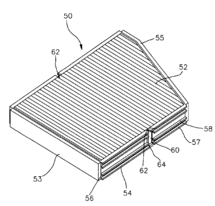
FIG. 6 is a perspective view showing the air filter device
according to the present invention, and FIG. 7 is a side view
of the air filter device shown in FIG. 6. As shown in FIGS. 6
and 7, an air filter 50 is largely classified into an air filter
member 52, a first frame member 57, a second frame member 54,
sponges 53 and 55, etc.
Air filter member 52 is provided with a plurality of
alternately-folded creases arranged at equal distances. Air
filter member 52 is adhered with first frame member 57, second
frame member 54 and a connecting frame member 60 for supporting
air filter member 52 along the marginal edge thereof.
First frame member 57 supports one side plane of air filter
member 52 and roughly half of both side planes connected to the
above side plane, and second frame member 54 supports the
remaining half of both side planes and the other side plane. The
height of first frame member 57 and second frame member 54 is
identical to the height of the creases.
Ribs 58 are respectively formed to side planes of first
CA 02241594 1998-06-24
WO 97/23360 PCT/KR96100247
13
frame member 57 and second frame member 54 in parallel with the
direction of being inserted with air filter 50. Ribs 58 are
protrudingly formed by using the direction of being inserted
with air filter 50 as the length direction. Ribs 58 numbering
four along the width direction of the frame are spaced apart
from one another by a predetermined distance to form a guide
groove 56 for allowing a bracket (not shown) to be inserted. In
particular, ribs 58 are formed to be symmetrical to both sides
with respect to a virtual plane which is placed to be high
enough to be half of the width height of the frame for the
purpose of maintaining the assembling compatibility of air
filter 50.
Connecting frame member 60 is disposed between first frame
member 57 and second frame member 54. The side plane of
connecting frame member 60 is substantially shaped as a
rectangle. Connecting frame member 60 has a corner of one end
connected to an end of first frame member 57 and a diagonal
corner of the other end connected to the end of second frame
member 54. The connection between connecting frame member 60 and
frame members 57 and 54 is accomplished by integrally injection-
molding connecting frame member 60 and frame members 57 and 54.
First notches 62 are formed to the connecting portion
between connecting frame member 60 and first frame member 57,
and second notches 64 are formed to the connecting portion
between connecting frame member 60 and second frame member 54.
Sponge 55 is installed to first frame member 57 where rib
CA 02241594 2000-11-03
14
58 is not formed, and sponge 53 is installed to second frame
member 54 where rib 58 is not formed. Especially, first frame
member 57 and air filter member 52 around the portion of being
installed with sponge 55 are asymmetrically shaped so as to
efficiently utilize a space within the interior of an engine
room.
FIG. 8 is an exploded perspective view showing a state that
the air filter device shown in FIG. 6 is installed to a left-
handed drive type automobile. As shown in FIG. 8, an air
regulating system 80 for automobile is placed between a left-
handed handle 85 and an engine room 88. A pair of holes 87a and
87b are .formed in the front of handle 85 for introducing
external air.
A shock absorber frame 86 mounted with a shock absorber
(not shown) inwardly projects to the interior of engine room 88
in the front diagonal direction of handle 85. A space with a
distance shorter than the length of air filter 50 is afforded
between shock absorber frame 86 and air regulating system 80.
A filter hole 84 is formed in shock absorber frame 86 at a
portion corresponding tv shock absorber frame 86. Air filter 50
is inserted into filter hole 84, and the entrance is sealed with
one side of a vacuum tank 82. Here, vacuum tank 82 performs a
separate function independent of air regulating system 80, but
is installed to the entrance side of filter hole 84 to serve for
tightly closing filter hole 84.
FIG. 9 is an exploded perspective view showing a state that
CA 02241594 2000-11-03
the air filter device shown in FIG. 6 is installed to a right-
handed drive type automobile. As shown in FIG. 9, an air
regulating system 70 for automobile is placed between right-
handed handle 75 and an engine room 78. A pair of holes 77a and
5 77b are formed in the front of handle 75 for introducing
external air.
A shock absorber frame 76 mounted with a shock absorber
(not shown) inwardly projects to the interior of engine room 78
in the front diagonal direction of handle 85. A space with a
10 distance shorter than the length of air filter 50 is afforded
between shock absorber frame 76 and air regulating system 70.
A filter hole 74 is formed in shock absorber frame 76 at a
portion corresponding to shock absorber frame 86 in air
regulating system 70. Air filter 50 is inserted into filter hole
15 74, and the entrance is sealed with one side of a vacuum tank
72. Here, vacuum tank 72 performs a separate function
independent of air regulating system 70, but is installed to the
entrance side of filter hole 74 to serve for tightly closing
filter hole 74.
The air filter device and the automobile having the same
constructed as above is operated as follows.
When the air filter device is intended to be installed to
the left-handed drive type automobile, second frame member 54
is upwardly bent with respect to first frame member 57 when
using the state shown in FIG. 6 as a reference. Then, the
bending is incited at pair of first notches 62 to widen the
CA 02241594 2000-11-03
16
angle between connecting frame member 60 and first frame member
57. This bending motion simultaneously appears at the creases
of air filter member 52 provided to the side of first notches
62. However, since the mutually attached state is maintained
unchanged, connecting frame member 60 and second frame member
54 swing in a body.
Under the state that second frame member 54 is bent, firs
frame member 57 is inserted into filter hole 84 in the
horizontal manner. While first frame member 57 is inserted,
second frame member 54 having been bent is returned to its
original position to force first frame member 57 and second
frame member 54 to place in the straight line. Thereafter,
second frame member 54 is pushed into the interior of filter
hole 84 unto sponge 55 is compressed. Upon the completion of
the inserting motion, vacuum tank 82 is installed to seal the
entrance of filter hole 84. The rear side of vacuum tank 82
seals the entrance of filter hole 84 while being closely
attached to sponge 53, and fixes air filter 50.
The air filter device is intended to be installed to the
right-handed drive type automobile, second frame member 54 is
downwardly bent with respect to first frame member 57 when using
the state shown in FIG. 6 as a reference. Then, overall air
filter 50 is up side down. By doing so, the bending is incited
at pair of second notches 64 to widen the angle between
connecting frame member 60 and second frame member 54. This
bending motion simultaneously appears at the creases of air
CA 02241594 2000-11-03
17
filter member 52 at the side of second notches 64. However, the
mutually attached state of connecting frame member 60 and first
frame member 57 is maintained unchanged.
Under the state that second frame member 54 is bent, first
frame member 57 is inserted into filter hole 74 in the
horizontal manner. While first frame member 57 is inserted,
second frame member 54 having been bent is returned to its
original position to force first frame member 57 and second
frame member 54 to place in the straight line. Thereafter,
second frame member 54 is pushed into the interior of filter
hole 74 until sponge 55 is compressed. Upon the completion of
the inserting motion, vacuum tank 72 is installed to seal the
entrance of filter hole 74. The rear side of vacuum tank 72
seals the ~3~trance of filter hole 74 while being closely
attached to sponge 53, and fixes air filter 50.
In association with the air filter device and automobile
having the same operated as above, the air filter can be
replaced without causing interference with the frame mounted
with a shock absorber while a cowl is not disassembled. Thus,
the present invention has an advantage of simplifying the
exchanging work of the air filter with the consequence of
affording convenience that a driver can individually replace the
air filter without requesting it to a service center, etc.
Furthermore, in the air filter device and automobile having
the same according to the present invention, the second frame
member can be upwardly bent without fail even though the upper
CA 02241594 1998-06-24
WO 97/23360 PCT/KR96/00247
18
and lower portions are reversed. This effect provides a
compatibility capable of being commonly employed into both the
left-handed drive type automobile and right-handed drive type
automobile. For this reason, the air filter can be simplified
by a single part. As the result, it is effective in economizing
the manufacturing cost of the air filter, enhancing
productivity, and the like.
While the present invention has been particularly shown and
described with reference to particular embodiment thereof, it
will be understood by those skilled in the art that various
changes in form and details may be effected therein without
departing from the spirit and scope of the invention as defined
by the appended claims.