Language selection

Search

Patent 2241682 Summary

Third-party information liability

Some of the information on this Web page has been provided by external sources. The Government of Canada is not responsible for the accuracy, reliability or currency of the information supplied by external sources. Users wishing to rely upon this information should consult directly with the source of the information. Content provided by external sources is not subject to official languages, privacy and accessibility requirements.

Claims and Abstract availability

Any discrepancies in the text and image of the Claims and Abstract are due to differing posting times. Text of the Claims and Abstract are posted:

  • At the time the application is open to public inspection;
  • At the time of issue of the patent (grant).
(12) Patent: (11) CA 2241682
(54) English Title: COLLECTION OF LUMBER PIECES FROM SPACED STACKS
(54) French Title: REGROUPEMENT DE PIECES DE BOIS D'OEUVRE PROVENANT DE PILES ESPACEES
Status: Expired
Bibliographic Data
(51) International Patent Classification (IPC):
  • B60P 1/36 (2006.01)
  • B60P 3/00 (2006.01)
  • E02F 3/76 (2006.01)
  • E02F 7/02 (2006.01)
(72) Inventors :
  • MCLEOD, JAMES A. (Canada)
(73) Owners :
  • MCLEOD, JAMES A. (Canada)
(71) Applicants :
  • MCLEOD, JAMES A. (Canada)
(74) Agent: ADE & COMPANY INC.
(74) Associate agent:
(45) Issued: 2006-04-25
(22) Filed Date: 1998-06-26
(41) Open to Public Inspection: 1999-02-26
Examination requested: 2003-01-09
Availability of licence: N/A
(25) Language of filing: English

Patent Cooperation Treaty (PCT): No

(30) Application Priority Data:
Application No. Country/Territory Date
08/917,687 United States of America 1997-08-26

Abstracts

English Abstract

An apparatus for picking and conveying lumber pieces from the ground for example for removing stacked support lumber during laying of a pipe line comprises a tracked vehicle carrying a transport conveyer across the rear of the vehicle and a conveyer table extending from the feed end of the main conveyer forwardly and downwardly toward the ground. At the forward picking end is provided a picker roller for lifting the lumber pieces from the ground. On one side of the picker roller is provided a drive conveyer which is generally vertical and driven at a high speed so that ends of the lumber pieces engaging the drive conveyer are driven rapidly rearwardly over the picker roller onto the conveyer so as to move along their length. On the side opposite to the drive conveyers provided a vertical flap which can pivot from side to side to push the lumber pieces toward the drive conveyer. The forward end of the conveyer table can be moved vertically and horizontally so as to engage the stack at the required position.


French Abstract

Appareil permettant de saisir et d'acheminer des pièces de bois de sciage qui se trouvent sur le sol, par exemple pour retirer un empilement de bois de sciage de soutien pendant la mise en place d'une canalisation, comprenant un véhicule à chenilles portant un convoyeur de transport à l'arrière du véhicule et une table de convoyeur s'étendant depuis l'extrémité d'alimentation du convoyeur principal vers l'avant et vers le bas en direction du sol. Au niveau de l'extrémité de saisie avant se trouve un rouleau de saisie destiné à soulever les pièces de bois de sciage du sol. Sur un côté du rouleau de saisie se trouve un convoyeur motorisé qui est généralement vertical et entraîné à grande vitesse de sorte que les extrémités des pièces de bois de sciage entrant dans le convoyeur motorisé soient entraînées rapidement vers l'arrière sur le rouleau de saisie sur le convoyeur de façon à se déplacer suivant leur longueur. Sur le côté opposé au convoyeur motorisé se trouve un volet vertical qui peut pivoter d'un côté à l'autre pour pousser les pièces de bois de sciage vers le convoyeur motorisé. L'extrémité avant de la table de convoyeur peut être déplacée verticalement et horizontalement de façon à mettre en prise l'empilement à la position requise.

Claims

Note: Claims are shown in the official language in which they were submitted.


-9-
CLAIMS:
1. Apparatus for collecting lumber pieces comprising;
a vehicle for moving a working direction across the ground
between stacks on the ground of the lumber to be collected;
a transport conveyer mounted on the vehicle for conveying the
lumber pieces from the stack on the ground to a transport container;
and a picking assembly for lifting the lumber pieces from the
ground on to the conveyer, the picking assembly comprising;
a conveyer table having a conveyer section thereon for transporting
the lumber pieces from a forward feed end of the conveyer table adjacent the
ground to a rear discharge end of the conveyer section;
means mounting the conveyer table for movement of the forward
end vertically up and down for adjustment of a height of the forward end;
means mounting the conveyer table for movement of the forward
end horizontally side to side for adjustment of a distance of the forward end
relative to the vehicle;
a toothed picker roller at the forward end in front of the conveyer
section and rotatable about a horizontal axis at right angles to the working
direction;
and a feed conveyer on one side of the forward end at one end of
the picker role for moving lumber pieces contacting the feed conveyer
rearwardly toward the conveyer section.
2. The apparatus according to Claim 1 wherein the feed
conveyer is driven at a rate faster than that of the picker roller and the
conveyer
section so as to move an end of a lumber piece engaging the feed conveyer


-9-
rearwardly to turn the lumber piece to present said end forwardly of the
lumber
in a direction of movement of the lumber piece.
3. The apparatus according Claim 1 wherein the feed conveyer
defines a substantially vertical surface.
4. The apparatus according to Claim 3 wherein the feed
conveyer comprises an endless belt having a pair of vertical drive rollers.
5. The apparatus according Claim 1 wherein the feed conveyer
extends along a part only of the table.
6. The apparatus according to Claim 1 including a pusher
member at an end of the picker roller opposite to the drive conveyer for
pushing
the lumber pieces toward the drive conveyer.
7. The apparatus according to Claim 6 wherein the pusher
member is pivotally mounted on the conveyer table for pivotable movement
about a vertical axis.
8. The apparatus according to Claim 6 wherein the pusher
member comprises a flap standing a substantially vertical plane.

Description

Note: Descriptions are shown in the official language in which they were submitted.


CA 02241682 1998-06-26
COLLECTION OF LUMBER PIECES FROM SPACED
STACKS
FIELD OF THE INVENTION
This invention relates to an apparatus for collecting lumber pieces
from spaced stacks of the lumber pieces.
BACKGROUND
In laying pipe such as in a gas or oil pipe line it is conventional that
lengths of the pipe are supported end to end on stack lumber pieces known as
"skids" so that the pipe lengths can be held at a required height to be
supported
and aligned end to end for welding of the lengths prior to feeding of the
completed welded length into a trench adjacent to the stacks.
Thus the pipe lengths are initially arranged end to end and are
properly aligned by arranging sufficient of the lumber pieces to support the
pipe
length at the required height. With the pipe lengths so supported, the welding
is carried out to form the lengths into a continuous length for laying in the
ground.
The continuous length is then lifted from the supporting stacks and
deposited into the ground by a train of tracked vehicles carrying suitable
operation element so that the lifted continuous pipe length can be feed from
the
supported position into the trench. After the pipe has been laid, it is
necessary
to collect the lumber pieces from the stacks and to discharge the collected
lumber pieces into a transport container for removal from the sight and
preferable for use at a further location along the pipeline.
A the present time the lumber pieces which are conventionally five
feet in length and 6 inches by 4 inches in cross section are lifted manually
and


CA 02241682 1998-06-26
-2-
handled manually for stacking onto a transport container. This manual process
is expensive and time consuming since it requires a gang of laborers working
vigorously at high wage rates. In many cases that stack has been disturb so
that the pieces are strewn and in some cases the pieces are compresses into
the ground by the tracks of the passing vehicles.
While this step relatively minor one in the process of laying the
pipe line, it constitutes a significant expense and therefore provides a
significant
opportunity for manufacturer of an effective machine which will carry out this
step while eliminating or reducing the manual labor involved.
SUMMARY
It is one object of the present invention therefore to provide an
improved machine for collecting lumber pieces which can be used in for
example in collecting the stacks or skids for supporting pipe lengths prior to
laying of the pipe.
According to one aspect of the invention there is provided
anApparatus for collecting lumber pieces comprising;
a vehicle for moving a working direction across the ground
between stacks on the ground of the lumber to be collected;
a transport conveyer mounted on the vehicle for conveying the
lumber pieces from the stack on the ground to a transport container;
and a picking assembly for lifting the lumber pieces from the
ground on to the conveyer, the picking assembly comprising;
a conveyer table having a conveyer section thereon for transporting
the lumber pieces from a forward feed end of the conveyer table adjacent the
ground to a rear discharge end of the conveyer section;


CA 02241682 1998-06-26
-3-
means mounting the conveyer table for movement of the forward
end vertically up and down for adjustment of a height of the forward end;
means mounting the conveyer table for movement of the forward
end horizontally side to side for adjustment of a distance of the forward end
relative to the vehicle;
a toothed picker roller at the forward end in front of the conveyer
section and rotatable about a horizontal axis at right angles to the working
direction; and a feed conveyer on one side of the forward end at one end of
the picker role for moving lumber pieces contacting the feed conveyer
rearwardly toward the conveyer section.
Preferably the feed conveyer is driven at a rate faster than that of
the picker roller and the conveyer section so as to move an end of a lumber
piece engaging the feed conveyer rearwardly to turn the lumber piece to
present
said end forwardly of the lumber in a direction of movement of the lumber
piece. Preferably the feed conveyer defines a substantially vertical
surface. Preferably the feed conveyer comprises an endless belt having a
pair of vertical drive rollers.
Preferably the feed conveyer extends along a part only of the table.
Preferably there is provided a pusher member at an end of the
picker roller opposite to the drive conveyer for pushing the lumber pieces
toward the drive conveyer.
Preferably the pusher member is pivotally mounted on the conveyer
table for pivotable movement about a vertical axis.
Preferably the pusher member comprises a flap standing a
substantially vertical plane.


CA 02241682 1998-06-26
-4-
BRIEF DESCRIPTION OF THE DRAWINGS
In the accompanying drawings, which illustrate an exemplary
embodiment of the present invention:
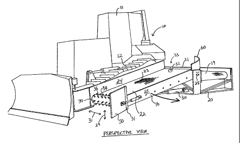
Figure 1 Is a perspective view of an apparatus according to the
present invention.
Figure 2 is a top plan view of the apparatus of Figure 1.
Figure 3 is side elevational view of the apparatus of Figure 1.
DETAILED DESCRIPTION
The apparatus comprises a conventional tracked vehicle 10 having
a cab 1 1 and a tracks 12 by which the vehicle can move across the ground in a
direction 13 of working movement. The vehicle carries a picking and conveying
system generally indicated at 14 including a main conveyer 15 and a conveyer
table 16 feeding the main conveyer 15.
The main conveyer is mounted behind the cab 11 of the vehicle
from the feed end 16 of the conveyer to a discharge end 17 of the conveyer,
the later feeding toward a transportation container shown schematically at 18.
The main conveyer 15 comprises a conveyer belt 19 carried on a frame 20
having a rear guide wall 21 for directing the lumber pieces along the conveyer
carried by the belt 19. The conveyer table includes a conveyer section 22
having a belt 23 similar to the belt 19 and mounted between side plates 24 and
on suitable drive rollers 26.
The conveyer table is inclined downwardly and forwardly from the
feed end 17a of the main conveyer along one track 12 to a forward picking end
27 of the conveyer table adjacent the front of vehicle 10.


CA 02241682 1998-06-26
-5-
The conveyer table 16 is mounted for pivotal movement about a
horizontal pivot shaft 28 defining a pivot access adjacent the feed end 17a
for
upward and downward vertical movement 29 of the forward end 27 of the
conveyer table. Actuation of the vertical movement 29 is effected by a
hydraulic drive cylinder 30 connected between the frame 20 and the underside
of the conveyer table 16.
The conveyer table is also mounted for horizontal side to side
movement 31. For this purpose the shaft 28 is mounted on a suitable swivel
mount 32 which allows the shaft to pivot about a vertical access 33 and thus
allow the conveyer table to move so that its forward end moves side to side
towards and away from the track 12. Actuation of the movement is effected
by a cylinder 34 connected between the side frame of the track 12 and a
bracket 35 on the underside of the conveyer table 16.
On the side wall 24 and 25 in front of the front roller 26a of the
conveyer belt 23 is provided a picker roller 36. The picker roller 36 is
mounted
on a shaft 37 carried in suitable bearings on the side plates 24 and 25 and
the
picker roller is driven by a motor 38 which rotates the picker roller in a
clock
wise direction tending to lift material from the ground on to the upper run of
the
belt 23. The picker roller 36 comprises a ridged cylindrical wall 38 on which
is
mounted a priority of rows of spikes 39 at angularly spaced positions around
the picker roll. Thus the spikes engage materials on the ground on can be
driven into the ground by adjusting the height of the table downwardly to
engage the ground thus tending to lift the lumber pieces from the ground or
from a position imbedded in the ground. The spikes thus project below the
bottom edges of the side plates 24 and 25.


CA 02241682 1998-06-26
-6-
the spikes are sufficiently sharp that they tend to engage into the
lumber in a picking action thus tending to lift the lumber pieces from the
ground. The forward roller 26a of the conveyer belt is located immediately
behind the picker roll so as to strip the lumber pieces from the picker role
so
that they are past over the top of the picker role and to feed the lumber
pieces
onto the belt 23 for transportation to the conveyer 15.
Attached to the side plate 24 is a drive conveyer 40 having a belt
41 supported on vertical rollers 42 and 43. The rollers are carried on a
horizontal top support plate 45 and a horizontal bottom plate 46 and are
driven
by a motor 47. The inside run of the belt facing toward the picker roller is
located in front of the picker roller and is driven a speed so that any lumber
pieces having an end engaging the drive conveyer are driven rapidly rearwardly
at a rate faster than the feeder rate of the picker roller and the belt 23 so
that
the end engaging the drive conveyer is driven rearwardly tending to align the
lumber pieces along the length of the conveyer belt 23.
On the opposite side to the drive conveyer is provided a pusher
member 50 in the form of a vertical flap or plate mounted for pivotal movement
about a vertical pivot access at the front of the side plate 25. Thus a hinge
structure 51 is mounted on the side plate 25 adjacent its forward end with the
flap 50 attach to the hinge structure 51 allowing the plate to move inwardly
and
outwardly as indicated at 52. Actuation of the movement is effected by a
cylinder 53 connected between outside surface of the side plate 25 and the
outside surface of the flap 50.
The operator thus can move the vehicle 10 along the direction of
movement 13 while adjusting the height and horizontal position of the forward


CA 02241682 1998-06-26
_ 7 _
end of the conveyer table so as to reach out to engage and grasp the lumber
pieces in the stack to one side of the vehicle. The flap 50 can then be
operated
to push the lumber pieces toward the drive conveyer 40 so that the end of the
lumber pieces adjacent the side plate 24 are moved rapidly rearwardly onto the
conveyer belt over the picker roller. The flap 50 can be actuated a number of
time to push lumber pieces toward the drive conveyer and to ensure that all
lumber pieces are properly moved from a resting or embedded position on or in
the ground onto the picker roller or onto the drive conveyer for lifting from
the
ground onto the conveyer belt 23.
At the upper rear end of the conveyer table is provided a guide wall
60 which provides a curved inside surface tending to turn the lumber pieces
from their movement lying longitudinal along the conveyer belt 23 so that the
lumber pieces move through a right angle and continue to move along their
length as they along the conveyer belt 19. Some of the pieces are thus feed
length wise through the conveyer system to the transport container 18.
While one embodiment of the present invention has been described
in the foregoing, it is to be understood that other embodiments are possible
within the scope of the invention. The invention is to be considered limited
solely by the scope of the appended claims.

Representative Drawing
A single figure which represents the drawing illustrating the invention.
Administrative Status

For a clearer understanding of the status of the application/patent presented on this page, the site Disclaimer , as well as the definitions for Patent , Administrative Status , Maintenance Fee  and Payment History  should be consulted.

Administrative Status

Title Date
Forecasted Issue Date 2006-04-25
(22) Filed 1998-06-26
(41) Open to Public Inspection 1999-02-26
Examination Requested 2003-01-09
(45) Issued 2006-04-25
Expired 2018-06-26

Abandonment History

Abandonment Date Reason Reinstatement Date
2003-06-26 FAILURE TO PAY APPLICATION MAINTENANCE FEE 2003-07-24

Payment History

Fee Type Anniversary Year Due Date Amount Paid Paid Date
Application Fee $150.00 1998-06-26
Maintenance Fee - Application - New Act 2 2000-06-27 $50.00 2000-06-19
Maintenance Fee - Application - New Act 3 2001-06-26 $50.00 2001-04-11
Maintenance Fee - Application - New Act 4 2002-06-26 $100.00 2002-06-17
Request for Examination $200.00 2003-01-09
Reinstatement: Failure to Pay Application Maintenance Fees $200.00 2003-07-24
Maintenance Fee - Application - New Act 5 2003-06-26 $75.00 2003-07-24
Maintenance Fee - Application - New Act 6 2004-06-28 $100.00 2004-06-21
Maintenance Fee - Application - New Act 7 2005-06-27 $100.00 2005-06-23
Final Fee $150.00 2006-02-08
Maintenance Fee - Application - New Act 8 2006-06-26 $100.00 2006-03-21
Maintenance Fee - Patent - New Act 9 2007-06-26 $100.00 2007-04-27
Maintenance Fee - Patent - New Act 10 2008-06-26 $125.00 2008-03-26
Maintenance Fee - Patent - New Act 11 2009-06-26 $125.00 2009-03-24
Maintenance Fee - Patent - New Act 12 2010-06-28 $125.00 2010-03-26
Maintenance Fee - Patent - New Act 13 2011-06-27 $125.00 2011-05-06
Maintenance Fee - Patent - New Act 14 2012-06-26 $125.00 2012-03-26
Maintenance Fee - Patent - New Act 15 2013-06-26 $225.00 2013-06-03
Maintenance Fee - Patent - New Act 16 2014-06-26 $225.00 2014-04-25
Maintenance Fee - Patent - New Act 17 2015-06-26 $225.00 2015-05-05
Maintenance Fee - Patent - New Act 18 2016-06-27 $225.00 2016-03-15
Maintenance Fee - Patent - New Act 19 2017-06-27 $225.00 2017-03-29
Owners on Record

Note: Records showing the ownership history in alphabetical order.

Current Owners on Record
MCLEOD, JAMES A.
Past Owners on Record
None
Past Owners that do not appear in the "Owners on Record" listing will appear in other documentation within the application.
Documents

To view selected files, please enter reCAPTCHA code :


To view images, click a link in the Document Description column. To download the documents, select one or more checkboxes in the first column and then click the "Download Selected in PDF format (Zip Archive)" or the "Download Selected as Single PDF" button.

List of published and non-published patent-specific documents on the CPD .

If you have any difficulty accessing content, you can call the Client Service Centre at 1-866-997-1936 or send them an e-mail at CIPO Client Service Centre.


Document
Description 
Date
(yyyy-mm-dd) 
Number of pages   Size of Image (KB) 
Abstract 1998-06-26 1 24
Representative Drawing 1999-03-19 1 10
Description 1998-06-26 7 245
Claims 1998-06-26 2 55
Drawings 1998-06-26 3 50
Cover Page 1999-03-19 1 63
Representative Drawing 2006-03-23 1 15
Cover Page 2006-03-23 1 51
Assignment 1998-06-26 3 86
Prosecution-Amendment 2003-01-09 17 522
Fees 2003-07-24 1 32
Correspondence 2006-02-08 2 49
Correspondence 2007-09-25 2 42