Note: Descriptions are shown in the official language in which they were submitted.
: CA 02242078 1998-08-07
6169-Myers et al.
POURING TUBE STRUCTURE AND ASSEMBLY
Background of the Invention
1. Field of the Invention
The present application relates to pouring appartatus for casting molten metals into molds.
More specifically, the invention relates to a pouring tube and tube holding apparatus for bottom-
pressure pouring molten metals from a holding ladle or tank.
2. Prior Art
Historically molten metals were initially cast by a gravity flow into either ingot form or
shaped molds. Methods were later developed to cast molten metals from the bottom of the mold.
The bottom pouring technique for casting molten metal into ingot molds utilized an elongate
tubular structure lined with refractory brick, which tube structure was higher than the height of
the ingot to be cast. A channel in the ingot mold stool extended from the bottom of the elongate
tube to the base of the open ingot mold with open outlets exposed to the mold interior.
Thereafter, molten metal poured through the tubular structure flowed to the ingot mold. This
casting technique produced ingots with less pipe and, therefore, greater recovery of the as-cast
steel.
Molten metal from a melting furnace is generally tapped into a ladle, which has a nozzle
in its base with a stopper and stopper rod assembly securing and controlling fluid flow from the
ladle. Control of the pouring rate of a bottom-poured ingot casting is, or can be, accomplished
by controlling the flow of metal from the ladle to the elongate tubular structure. Discussion of
these pouring practices and some illustrative ingot mold and ladle nozzle assemblies are shown in
Basic Open Hearth Steelm~king, from the American Tn~til~lte of Mining, Metallurgical, and
Petroleum F.ngin~ers, New York, 1964. Other illustrative casting mold structures for bottom
pouring are schem~tic~lly illustrated in the Making, Shaping and Treating of Steel, United States
Steel Corporation, 1964.
Similarly, ladles are used to transfer molten metal for casting into sand molds, die
casting or other casting operations. These casting techniques utilize the gravity feed method
- CA 02242078 1998-08-07
or an operation similar to the bottom-poured ingot casting. However, there are inherent
problems with heat loss and rate of pouring which impact the integrity of the cast product both
internally and externally. As a consequence, a bottom-pouring casting technique lltili~ing the
pressurization of a ladle to forcibly move molten metal, particularly steel, was developed. In
this method, metal is transferred into a mold without tral~rerlhlg it through a long, tortuous,
brick-lined channel, which was expensive to construct and m~int~in as well as resulting in
significant heat losses. This bottom-pressure casting technique was developed in the middle of
the twentieth century and has found particular application in the production of railroad wheels,
as it produces wheels with consistent internal integrity and with a minim~l number of external
- flaws.
One of the problems associated with this bottom-pressure casting is communication of
the molten metal to the mold. This requires elevation of the gas pressure above the molten
metal bath in the sealed ladle or holding tank to mechanically force the molten metal up a
pouring tube. Further, the seal between the mold and the pouring tube must be m~int~in,ocl to
sustain a steady gas pressure for smooth transfer of molten metal to the mold. Consequently,
mold equipment and casting practices are constantly under review and development, as their
improvement leads to higher quality products and generally lower costs of production, through
the lowering of labor or tool costs, for example.
Illustrative of the concern for m~int~ining the structure of the pouring tube is the
teaching of U.S. Patent No. 3,054,155 to Zickefoose. In this patent, the general structure and
physical characteristics of the pouring tubes are described and the exposure of the tubes to the
hostile environment of molten metal is noted. The reduction in thermal shock to the tube from
a large change in temperature was accommodated by preheating the tube in accord with the
thermal expansion characteristics of the specific tube material. The illustrated tilt to the
pouring tube structure was to prevent the el"laplllent of air within the casting cavity. As noted
in Figure 2 of the Zickefoose -'155 patent, pouring tube 21 is a cylindrical tube with a straight
outer sidewall, which tube is secured in housing 12 by a cement like mixture 22. There is no
mechanical consideration for the tube and/or tube assembly to bear the vertical load from the
mold.
CA 02242078 1998-08-07
U.S. Patent No. 3,279,003 to Yates discloses a means to m~int~in a vertically
arranged, refractory, cylindrical tube in position for casting molten metals. A steel shell
around the refractory tube provides strength and forms an impermeable membrane. A cement
is placed between the refractory tube and the steel shell to secure the tube in position. U.S.
Patent No. 3,322,186 to Takacs, Jr. et al. taught a means to accommodate the vertical motions
acting on the pouring tube or more broadly on the casting and mold apparatus arrangement. In
an effort to mate the two components, mold and pouring apparatus, power driven cylinder
rams were taught for raising and lowering the pouring tube. Pouring tube 22 is a straight
tubular shape with a head element 58 secured on its upper end, and head element 58 fits into a
recess in the gate assembly 40 of the car and mold unit. In Figure 2 of this Takacs,Jr. et al. -
' 186 patent, tube 52 is mated in casing 56 and refractory sand 54 is interposed between casing
56 and tube 52. Another arrangement for holding the pouring tube is illustrated in Figure 3,
wherein a refractory cement 106 is noted between tube 102 and metal sheath 108. However,
there is no mechanical, vertical support for tubes 22 or 102 in any of these disclosures.
Another pouring tube structure is noted in U.S. Patent No. 3,508,615 to Troy, wherein
vertical tube 32 is secured in position by refractory grout 58 between ferrule 30 and the tube
outer wall. In addition, an impermeable sleeve 60 is mounted at the lower end of tube 32 and
m~int~in~cl in position by refractory wrap 64. None of the above-cited disclosures
accommodates the vertical loads placed upon the tube by the mold or mold assembly.
The present invention provides an assembly to more securely retain the pouring tube in
position while reducing its exposure to mechanical damage from the mold. The resulting
better seat for the mold also provides a more consistent positioning of the mold or mold nozzle
and a better retention of the gas pressure head in the molten metal ladle or holding tank.
SUMl\IARY OF THE INVENTION
The present invention provides a pouring tube assembly for a bottom-pouring casting
apparautus or pouring tank arrangement. The pouring tube assembly includes a mechanical
constraint for the pouring tube, holding casting and parting ring, which results in a secure
union of the components. The pouring-tube assembly is integratable into present equipment
CA 02242078 1998-08-07
without excess development and redesign. The integrity of the gas-tight, holding-tank seal is
enh~nre~, and the pouring tube upper end is more protected from mechanical damage than in
present structures. Protection of the structural integrity of the pouring tube head or upper end,
which is in proximity to the mold nozzle or nozzle well, is an important consideration in
casting practice, as it is imperative to avoid metal leakage from the tube end and the
entrainment of tramp gasses from the atmosphere. These pouring tubes are by necessity a
refractory or ceramic material, as the pouring tube is exposed to elevated temperatures and
erosion from flowing molten metal. However, these ceramic materials are generally brittle
and susceptible to fracture. Consequently, it is nPcess~ry to provide as secure an environment
as possible for the protection of these tubes and their exposed tube ends.
BRIEF DESCRIPTION OF THE DRAWING
In the several figures of the Drawing, like reference numerals identify like components,
and in those drawings:
Figure 1 is a cross-sectional view of an extant pouring tube assembly and holding tank
for a bottom-pouring casting apparatus;
Figure 2 is an enlarged cross-sectional elevational view of an extant pouring tube and
tank cover assembly;
Figure 3 is a cross-sectional elevational view of the pouring tube and tank cover
assembly;
Figure 4 is a cross-sectional view of the pouring tube in Figure 3;
Figure 5 is a cross-sectional view of the holding casting in Figure 3;
Figure 6 is a plan view of the holding casting in Figure 5;
Figure 7 is a cross-sectional elevation of the parting ring of the assembly of Figure 3;
and,
Figure 8 is a plan view of the parting ring of Figure 7.
DETAILED DESCRIPTION OF THE PREFF,RR~,n EMBODIMENT
An exemplary prior art bottom pouring tube assembly and holding tank arrangement 10
CA 02242078 1998-08-07
are noted in Figure 1. In this figure, ladle 12 is nested in holding tank 14. Tank cover 16 and
pouring tube assembly 18 are positioned on tank top 20 to seal chamber 22 and, thus, the
molten metal in ladle 12. Pouring tube 24 extends from tank cover 16 into ladle 12 in
proximity to ladle bottom 26. This extant arrangement 10 is illustrative of a practice and
apparatus utilized for bottom pressure pouring of molten metals and is used for casting railroad
wheels.
In a pouring practice l1tili7ing arrangement 10 in Figure 1, mold 28 is mounted on
holding ring 30 on tank cover 16. A gas, such as air or an inert gas, is pumped into chamber
22 through an orifice or valve (not shown) to elevate the pressure above the molten liquid in
ladle 12. The elevated pressure above the molten metal bath increases the pressure until the
molten metal is forced up passage 32 of tube 24 into a cavity (not shown) of mold 28.
The structure of arrangement 10 is both large and heavy. Indicative of the mass of the
several components it is noted that a railroad wheel weighs 500 pounds or more. Therefore,
the components for casting such parts are significant in size. As an example, mold 28 has
plate-steel frame 34 for cont~ining a blank pattern in sand or graphite to retain the molten 500
pounds of steel. Mold 28 and the cast wheel therein are nested on pouring tube assembly 18
atop cover 16, which cover 16 has plate metal top 36 with refractory material layer 38 and
heat cover 40. Ladle 12 in tank 14 generally contains enough molten metal to cast several
wheels, which implies about 3 or 4 tons of molten metal. In addition, ladle 12 has a plate
metal shell and multiple layers of refractory brick lining, which add significant weight to the
already noted heavy components. It can thus be appreciated that the relatively large size of the
parts to be cast requires casting equipment components of significant mass. As a specific
example, it is known that pouring-tube holding-casting 42 of pouring tube assembly 18 may
weigh about 20Q pounds, but it appears as a relatively small component in Figure 1. In
consideration of these large components, it is readily apparent that m~ch~nic~l strength of the
casting equipment components is a requisite, and that protection of the smaller, or more
fragile, components in a casting practice is nl-ce~s~ry if they are to survive the harsh
environment of molten metal at elevated telllpeldLules and the interaction with massive weight
equipment elements.
CA 02242078 1998-08-07
Figure 2 shows a pouring tube assembly 18 similar to the pouring tube assembly of
arrangement 10 in Figure 1. In this enlarged view of Figure 2, assembly 18 has pouring tube
24 with outer (li~m~ter 44 and inner or passage tli~m~ter 46. Passage 32 with inner wall 33 is
noted as a cylinder extending from tube lower end 48 to upper end 50. Tube gasket 52 is
seated on upper end 50 and provides a better seat and seal for mold 28. Tube 32 in this
illustration includes first circumferential slot 54 and second chculllr~lellLial slot 56 on its outer
wall 58. Holding casting 42 is generally cylindrical with top 60, bottom 62 and duct 64
extending through casting 42. First inner wall 66 of casting 42 has first inner diameter 67
extending from top 60 to internal wall protrusion 68. Second inner wall 70 has second inner
diameter 72 extending from bottom 62 to wall protrusion 68, which second inner wall
diameter 70 is less than first inner wall (li~m~ter 67. In Figure 2, holding casting outer wall
74 has collar 76 with outer ~ m~ter 78, which collar 76 has upper surface 80 in proximity to,
but downwardly displaced from, top 60 to form first shoulder 82 with sidewall 84. Lower
surface 86 of collar 76 intersects with outer wall 88 of holding-casting 42 at second shoulder
90. Outer wall 88 inwardly tapers from second shoulder 90 toward longitn~lin~l axis 92 of
tube 24 and holding casting 42 to intersect bottom 62. There is an inflection point or ridge 94
in the slope of outer wall 88 where the angle of the taper increases toward longitll~in~l axis
92.
Parting ring 100 is about an annulus with top side 102, bottom side 104, outer diameter
106 and inner diameter 108. Parting-ring outer wall 110 at outer diameter 106 vertically
extends downward beyond the horizontal plane of bottom side 104 and includes inner wall
112. Shoulder 114 occurs at the intersection of parting-ring bottom side 104 with inner wall
112, which has inner ~ m~ter 118. Parting-ring bore 116 has inner diameter 108, which is
larger than outer-wall tii~m~oter 44 of tube 24.
Holding ring 30 in Figure 2 has a cross-section which appears as an annulus withsloped outer walls 124. In Figure 2, holding ring 30 has central through-bore 31, upper face
120 with first outer ~ meter 126 and first inner ~ mPter 128. Lower face 122 has second
outer diameter 130 and second inner ~ m~.ter 132, which second outer diameter 130 is larger
than upper-face first outer tli~m~ter 126, and second inner ~ m~ter 132 is greater than first
CA 02242078 1998-08-07
inner diameter 128. Outer wall 124 is tapered from first outer diameter 126 to second outer
diameter 130 to provide ring 30 as a generally frustum-shaped annulus in Figures 1 and 3.
Holding-ring first inner wall 134 with first inner ~i~ml ter 128 downwardly extends from
upper face 120 to meet horizontal internal wall 138. Second inner wall 136, which is
displaced radially outward from axis 92 and first inner wall 134, upwardly extends from lower
face 122 to intersect horizontal internal wall 138 at shoulder 140. Lower face 126 of ring 30
contacts support ring 150, which also appears as an annular member and is positioned on tank
cover 16 with holding casting 42 extending through support-ring central bore 152.
Cementitious refractory material is applied in passage 64 between tube 24 and holding
casting 42. A space or gap 61 is not filled at the upper end of passage 64, as part of the
assembly practice of tube assembly 18 in Figure 2.
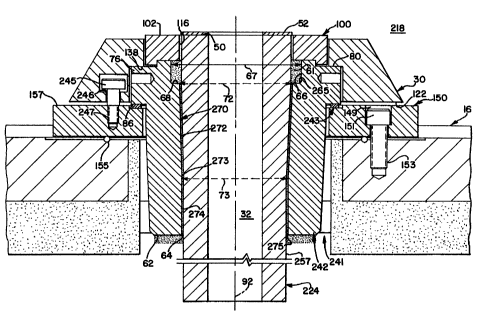
In Figure 3, the plcrcllcd embodiment of the present invention is noted as pouring-tube
assembly 218 with holding casting 242, pouring tube 224, parting ring 100, holding ring 30,
tube support ring 150 and gasket 52. Holding casting 242 and pouring tube 224 are matable in
the same general manner as the above-noted holding casting 42 and tube 24. However, in
Figures 3 and 5 of this plcfellcd embodiment, holding casting 242 has internal wall protrusion
68 in closer proximity to top 60 than does casting 42. Intersection or shoulder 265 of sidewall
or first inner wall 66 in casting 242 appears as a radius and not as a square corner. This is
merely as an illustration and not a limitation.
Holding-casting 242 has lower inner wall section 270 extending from internal wall
protrusion 68 to bottom 62. Tapered and upper inner wall segment 272 of wall section 270
extends from second ~ mpter 72 to third inner ~ m~ter 73, which is smaller than second
inner diameter 72. Upper and tapered inner wall segment 272 extends from second inner
diameter 72 at wall protrusion 68 downward to third inner ~ m~ter 73. Lower and generally
cylindrical segment 274 generally vertically extends from third inner (li~m~ter 73 to casting
bottom 62 and intersects tapered segment 272 at inflection point 273. In Figure 5, holding-
casting, upper, outer-wall section 74 extends generally vertically dowllwal-l from collar lower
face 86. At outer-wall inflection point 94, lower outer wall section 88 angularly tapers inward
toward axis 92 to intersect casting bottom 62. Holding casting 242 is shown in plan view in
CA 02242078 1998-08-07
Figure 6, which illustrates aperture 64, first inner diameter 67, second inner diameter 72 and
third inner diameter 73, as well as providing an illustration of the narrow inward taper of
vertical wall 270.
Pouring tube 224 in Figures 3 and 4 has longitudinal axis 92 and outer wall 258.Passage 32 is generally cylindrical and has inner wall 33 extending between tube lower end 48
and upper end 50, which tube lower end has outer ~ m~ter 44. Tube outer wall 258 has
upper segment 255 with second tube outer diameter 244 extending from upper end 50 to first
inflection point 251 in Figure 4, which second outer cli~m~ter 244 at tube top 50 is greater
than outer diameter 44 at tube bottom 48. Tube, outer-wall, lower segment 257 with outer
diameter 44 extends generally vertically from tube lower end 48 to second inflection point 253
along wall 258. Third and tapered outer-wall segment 259 is inwardly tapered from first
inflection point 251 to second inflection point 253 and diameter 44. Third wall segment 259 is
noted in Figure 4 with inwardly tapering angle 261, which angle may be 2~ from vertical, for
example.
Parting ring 100 is shown in Figures 7 and 8, and as noted above has inner diameter
108, which is larger than ~ m~ter 244 of tube 242. In Figure 7, wall 112 with inner diameter
118 extends from lower wall or bottom side 104 to outer bottom surface llS, which inner wall
112 and lower wall 104 provide recess 117 to receive upper surface 60 of holding casting 242.
In the illustration of Figure 3, tube support ring lS0 is seated on tank cover 16 and
secured in position by screws 151 extending through bores 149, which are anchored in ports
153 of cover 16. Garlock gasket 155 is nested between tank cover 16 and tube support ring
150 to seal the surfaces between these two components and to avoid seepage or pressure loss
during casting.
Holding casting 242 is positioned in opening 241 of tank cover 16 with holding-casting-
collar lower surface 86 positioned on tube-support-ring upper surface 157 with pouring tube
gasket 243 positioned therbetween to m~int~in a tight seal. Internal wall 138 of holding ring
30 contacts upper surface 80 of holding casting collar 76, and holding-ring lower face 122
contacts tube-support-ring upper surface 157. Screws 245 of holding ring 30 extend through
CA 02242078 1998-08-07
passage 246 to mate with support-ring passages 247 and secure holding ring 30 to support ring
150.
Pouring tube 224 is placed in holding-casting aperture 64 with lower segment 257extending through aperture 64. In this configuration, holding-casting third inner diameter 73
is approximately equal to, or slightly larger than pouring tube outer diameter 44 at second
inflection point 253. Similarly, tapered tube wall segment 259 is sloped or tapered to
generally conform to the slope of holding casting wall section 270 between holding casting
inner diameter 72 and inner di~m~ter 73. Upper section 255 with outer diameter 244 extends
from inflection point 251 to upper surface 50. After assembly, a narrow gap 275 exists
between inner wall 270 of holding casting 242 and pouring tube outer wall 258. This gap is
filled with a cementitious refractory compound, which provides both an anchoring and
insulating material between holding casting 242 and pouring tube 224.
Parting ring 100 is mated with holding casting upper portion 230, which has outer
diameter 232 about equal to parting ring inner diameter 118 to again nest parting ring 100 on
upper portion 232 in recess 117. Tube upper segment 255 extends past holding casting top
surface 60 to mate with parting-ring bore or port 116. In this arrangement, tube upper surface
50 is about coplanar with parting-ring top surface 102. Gasket 52 is secured to tube upper
surface 50 for receipt of a mold 28.
In assembly 218, tube 224 is firmly nested in holding casting 242. Upper segment 255
has a larger diameter 244 than lower diameter 73 of holding casting 242, consequently, tube
224 is anchored in aperture 64 by both the cementitious refractory material and by the
mechanical force of gravity wedging tube wall 258 against holding casting wall 270. In this
preferred embodiment, the taper of walls 270 and 258 are approximately equal, and the outer
~i~m~ters of tube 224 are only smaller than the inner wall diameters of holding casting
aperture 64 to allow assembly of the components and the introduction of the cementitious
refractory material. However, the narrow gap 275 will not permit free passage of tube 224
through holding-casting aperture 64. Thus, positioning a mold 28 atop holding tank cover 16
and holding ring 30 will more firmly nest tube 224 into holding casting 242. This latter action
is to prevent tube 224 from being driven out of holding casting 242 as has been experienced
CA 02242078 1998-08-07
with present structures. Tube 224 has a length from bottom 48 to upper end 50 to allow tube
224 to extend into ladle 16 in proximity to ladle bottom 26, and to protrude above holding ring
upper face 120 but providing top end 50 approximately level with parting ring top surface 102.
While the present invention has been described in connection with certain specif1c
embodiments thereof, it is apparent that various alterations and modifications can be made
therein. It is, therefore, the intention in the appended claims to cover all such modifications
and alterations as may fall within the scope and spirit of the invention.