Note: Descriptions are shown in the official language in which they were submitted.
CA 02242148 1998-07-03
METHOD OF SEALING JOINTS BETWEEN ADJACENT
SHEET PILING SECTIONS TO FORM A CONTINUOUS BARRIER
AND BARRIERS FORMED USING SAID METHOD
FIELD OF THE INVENTION
The present application relates to in-ground barriers comprising sections of
sheet
piling driven into the ground to form a wall, cofferdam or the like. In
particular, the present
invention relates to watertight connecting joints between adjacent sections of
in-ground sheet
piling that form a continuous barrier which restricts the migration of
groundwater and other
liquids.
BACKGROUND OF THE INVENTION
Interlocking sections of sheet piling driven into the ground is a popular,
cost-
effective method for instaUing barrier walls to prevent the movement of soils
and limit
groundwater migration. Typical sheet piling sections are made of steel plates
and have connectors
on the side edges. The sheet piling sections are installed sequentially by
interlocking the
connectors of adjoining sheet piling sections to form a continuous barrier.
However, standard
sheet piling barriers are not watertight since the interlocking joints provide
a potential flow path
for the passage of groundwater and other liquids. Attempts have been made to
seal the joints
between sections of sheet piling but these attempts have been difficult and
expensive to implement
and have not always provided a watertight seal.
2
CA 02242148 1998-07-03
Previously known methods for forming watertight seals between interlocking
sheet
piling sections use interlocking mechanisms that form cavities when connected
to the adjoining
section. After the sheet piling sections are driven into the ground, soil,
vegetation and other
materials that accumulate in the cavities when the sheet piling sections are
driven into the ground
are removed and the cavities are then filled with a sealant to form a
watertight barrier. These
methods encounter several problems that make it time consuming and expensive
to form a
satisfactory watertight seal. Before the cavities can be filled with a
sealant, the materials
accumulated in the cavities have to be removed using time consuming and labor
intensive
methods. However, once the barriers are installed in the ground, it is
difficult to insure that all of
the materials have been removed from the cavities. If any materials are left
in a cavity, the sealant
may not completely fill the cavity when it is added and a potential flow path
is created for
groundwater to pass through the barrier.
Several patents describe specially constructed sheet piling sections with
interlocking joints which form a cavity that is filled with a sealing
material. U.S. Patent No.
3,302,412 to Hunsucker discloses interloclcing thumb and finger elements which
form a cavity
between adjacent sheet piling sections that is filled with a sealant. U.S.
Patent No. 5,163,785 to
Zanelli et al. employ an interlocking sheet piling mechanism shaped like claws
that form a cavity
for sealant material. U.S. Patent No. 5,437,520 to Cherry et al. teach joints
between pile-driven
sheet piles having edge forms which interlock to form two cavities that are
filled with a sealant.
Certain other types of prior constructions have been tried, but these
constructions
have required the cavities to be cleaned out after the sheet piling sections
are installed before the
3
CA 02242148 1998-07-03
sealant material is added. Thus, all prior constructions have the inherent
disadvantages common
to those above denoted relative to materials accumulated in the cavities
formed by the
interlocking joints when the sheet piling sections are installed.
Another disadvantage of previously known methods is inherent in the fact that
they
require specially fabricated sheet piles and cannot use standard sheet piles.
Also, the interlocking
joints of these specially fabricated sheet piles are easily damaged when
installed in the ground,
either making it difficult to fill the cavities with the sealant or preventing
the joint from being
properly sealed. An additional disadvantage specially fabricated sheet piles
used in previously
known methods is that they cannot easily be disassembled and reused because
the interlocking
connectors are damaged when the sheet piling sections are removed from the
ground.
SUMMARY OF THE INVENTION
The present invention discloses a method of sealing the joints between
sections of
standard sheet piling to provide a continuous barrier to the migration of
groundwater. This
method can also be used to seal the joints between nonstandard sheet piling
sections. Sheet piling
sections covered by the present invention include: sheet piling sections made
of steel, iron,
aluminum, or alloyed metals, double wall sheet piling sections, and preformed
sheet piling
sections made of cement, concrete, and composite materials.
Sheet piling sections are typically installed by sequentially driving
individual
4
CA 02242148 1998-07-03
sections of sheet piling into the ground. Sheet piling sections are connected
to adjacent sheet
piling sections by means of interlocking joints on the abutting side edges of
the sheet piling
sections. The joints so formed are not watertight and barriers formed by these
sheet piling
sections do not prevent the migration of groundwater. It has been discovered
that a watertight
seal can be formed by attaching a housing containing a sealant material to a
sheet piling section
prior to installation.
By various aspects of this invention, one or more of the following or other
objectives can be obtained.
It is an object of this invention to provide a method of sealing the joints
between
sheet piling sections that can be easily and economically implemented with
readily available
materials. The method uses standard sheet piling sections and sealing
materials to form an
impermeable seal.
It is a further object of this invention to provide a method for sealing sheet
piling
sections that can be used with standard sheet piling sections or that can be
incorporated into the
design of sheet piling sections when they are manufactured.
It is still a further object of this invention to provide a method for sealing
sheet
piling sections that does not damage the connecting edges of the sheet piling
when the sheet piling
is removed so that the sheet piling sections can be easily reused.
CA 02242148 2002-12-11
Another object of this invention is to provide a method for sealing the
joints between sheet piling sections with damaged connecting edges that do not
tightly
interlock with the adjoining sheet piling sections.
A further object of this invention is to provide a method for forming a
casing for a test well on either one or both sides of a sheet piling section.
Other aspects, objects, and the several advantages of this invention are
apparent to one skilled in the art from a study of this disclosure, the
drawings, and the
appended claims.
According to the present invention, a housing comprising a removable
barrier and containing a sealant material is attached to a sheet piling
section parallel to
and overlapping the connecting edge prior to installation. After the sheet
piling section is
installed, the barrier is removed and the sealant material contacts the
interlocking joint
and the adjacent sheet piling sections to form a watertight seal.
The present invention provides a method of sealing a connection between
a first sheet piling section and a second sheet piling section, wherein the
second sheet
piling section comprises a first side edge which connects to the first sheet
piling section
to form an interlocking joint, the method comprising the steps of installing
the first sheet
piling section in the ground, attaching a housing comprising an interior wall,
an exterior
wall, an open top end, a closed bottom end and an open side to the second
sheet piling
section, wherein the housing extends beyond the first side edge of the second
sheet piling
section, placing a barrier between the open side of the housing and the second
sheet
piling section, adding a sealant material to the housing, installing the
second sheet piling
section and the housing iri the ground, and removing the barrier, wherein the
sealant
material contacts the first and second sheet piling sections and the
interlocking joint to
form a seal between the first and second sheet piling sections.
6
CA 02242148 2002-12-11
The present invention also provides a method of sealing a connection
between a first sheet piling section and a second sheet piling section,
wherein the second
sheet piling section comprises a first side edge which connects to the first
sheet piling
section to form an interlocking joint, the method comprising the steps of
installing the
first sheet piling section in the ground, attaching a length of angle steel to
the second
sheet piling section, wherein the angle steel comprises an open top end, a
closed bottom
end, a first wall, a second wall and an angle formed by the first and second
walls,
wherein the first and second walls extend outwardly from the angle to a first
edge and a
second edge respectively, and wherein the first edge of the angle steel is
attached to the
second sheet piling section and the second edge extends beyond the first side
edge of the
second sheet piling section, placing a barrier between the angle steel and the
second sheet
piling section, wherein the barrier, the closed bottom end and the first and
second walls
form a cavity, adding a sealant material to the cavity, installing the second
sheet piling
section and the angle steel in the ground, and removing the barrier, wherein
the sealant
material contacts the first and second sheet piling sections and the
interlocking joint to
form a seal between the first and second sheet piling sections.
The provides invention also provides a method of sealing a connection
between a first sheet piling section and a second sheet piling section,
wherein the second
sheet piling section comprises a first side edge which connects to the first
sheet piling
section to form an interlocking joint, the method comprising the steps of
installing the
first sheet piling section in the ground, attaching a half pipe section to the
second sheet
piling section, wherein the half pipe section comprises a first longitudinal
side edge, a
second longitudinal side edge, an open side, an open top end and a closed
bottom end,
and wherein the first longitudinal side edge of the half pipe section is
attached to the
second sheet piling section and the second longitudinal side edge extends
beyond the first
side edge of the second sheet piling section, placing a barrier between the
open side and
the second sheet piling section to form a cavity, adding a sealant material to
the cavity,
installing the second sheet piling section and the half pipe section in the
ground, and
removing the barrier, wherein the sealant material contacts the first and
second sheet
6a
CA 02242148 2002-12-11
piling sections and the interlocking joint to form a seal between the first
and second sheet
piling sections.
The present invention also provides a continuous in-ground barrier
comprising a plurality of sheet piling sections, wherein a first sheet piling
section and a
second sheet piling section comprising a first side edge are connected to form
an
interlocking joint and the joint is sealed by a device comprising a housing
comprising a
top end, a closed bottom end and an open side, wherein the housing is attached
to the
second sheet piling section and extends beyond the first side edge, a barrier
inserted
between the open side of the housing and the second sheet piling section to
form a cavity,
and a sealant material added to the cavity, wherein after the first sheet
piling section is
installed in the ground, the second sheet piling section and attached housing
are installed,
the barrier is removed and the sealant material contacts the interlocking
joint.
The present invention also provides a continuous in-ground barrier
comprising a plurality of sheet piling sections, wherein adjacent sheet piling
sections are
connected to form an interlocking joint, and wherein the interlocking joint is
sealed by a
device comprising a housing comprising a top end, a closed bottom end and an
open side,
wherein the closed bottom end slopes downwardly and the housing is attached to
a sheet
piling section and extends beyond the interlocking joint, a barrier slidably
inserted
between the open side of the housing and the sheet piling section, and a
sealant material
added to the housing, wherein the sheet piling section is installed in the
ground, the
barrier is removed and the sealant material contacts the interlocking joint.
The present invention also provides a device for sealing an interlocking
joint formed by a first sheet piling section and a second sheet piling
section, wherein the
device comprises a housing comprising a first side edge and a second side
edge, wherein
the side edges define an open side, a removable barrier between the open side
of the
housing and the sheet piling section, and a sealant material added to the
housing, wherein
when the first and second sheet piling sections are installed, the first side
edge is attached
to the first: sheet piling section and the second side edge is juxtaposed with
the second
6b
CA 02242148 2002-12-11
sheet piling section and the sealant material contacts the interlocking joint
when the
barrier is removed.
The present invention also provides a method of fabricating a groundwater
monitoring system comprising slidably attaching a housing comprising a top end
and a
bottom end to a side wall of a sheet piling section, inserting a groundwater
monitoring
well in the housing, installing the sheet piling section and the housing in
the ground, and
withdrawing the housing.
The present invention also provides a groundwater monitoring system
comprising a sheet piling section, a housing slidably attached to the sheet
piling section
to be partially or fully withdrawn after installation with the sheet piling
section in the
ground, and a groundwater monitoring well inserted in the housing.
The present invention also provides a groundwater monitoring system
comprising a sheet piling section, a boot, a housing attached to the sheet
piling section,
and a groundwater monitoring well inserted in the housing, wherein the housing
comprises a top end and a bottom end and the boot is attached to the bottom
end of the
housing and wherein the sheet piling section and housing are installed in the
ground and
the housing is partially or fully withdraw after installation.
In one embodiment of the invention, a "hydroswellable" sealant
material is used, preferably bentonite. The liquid reagent is preferably added
to the
"hydroswellable" sealant material after the housing is attached to the sheet
piling
section and prior to installation. However, the sealant material can also be
hydrated by means of a perforated tube or pipe positioned along the
longitudinal
axis of the housing after the housing and sheet piling section are installed
in the
ground and the barrier is removed. The liquid reacts with the sealant material
to
6c
CA 02242148 1998-07-03
increase the volume and insure a tight seal around the joint. In another
embodiment, a
polyurethane foam is injected into the housing under pressure and subsequently
solidifies to form
a watertight seal. In still another embodiment, a metal tube is placed in the
housing extending
along its longitudinal axis and plastic, rubber, silicone or other synthetic
material in the form of
resins or pellets is packed into the housing around the tube. After the sheet
piling section and the
attached housing have been installed in the ground, the barrier is removed and
a heating element is
inserted into the tube to heat the sealant material to a temperature above its
melting point. After
the sealant material has melted, the heating element is withdrawn from the
tube and the sealant
material solidifies to form a watertight seal.
BRIEF DESCRIPTION OF THE DRAWINGS
In the drawings:
Fig. l is a plan view of an instailed sealant apparatus showing the
interlocking joint
formed by two sheet piling sections, the housing, the barrier and the sealant
material.
Fig. 2 is an oblique view of a barrier as it is being inserted between a
housing and a
sheet piling section prior to installation in the ground.
Fig. 3 is a side elevation of a housing, a tube, a barrier and a sheet piling
section.
Fig. 4 is an oblique view of a housing attached to an installed sheet piling
section
prior to the withdrawal of the barrier.
7
CA 02242148 1998-07-03
Fig. 5 is a side elevation of a series of sheet piling sections that are being
installed
to form a continuous wall.
Fig. 6 is a side elevation of a housing formed from a half pipe section and
shows a
boot and wedges.
Fig. 7 is an oblique view of a packing assembly mounted on a housing attached
to
an installed sheet piling section prior to the withdrawal of the barrier.
Fig. 8 is a plan view of a housing and a monitoring well mounted on the side
wall
of a sheet piling section.
Fig. 9 is a side elevation of a housing, a monitoring well, a boot and a sheet
piling
section before the sheet piling section is installed in the ground.
Fig. 10 is a side elevation of a housing, a monitoring well, a boot and a
sheet piling
section after the sheet piling section has been installed in the ground.
DESCRIPTION OF THE PREFERRED EMBODIlVIENT
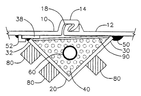
Referring to the accompanying drawings, Figs. 1 through 5 show a preferred
embodiment of the present invention. According to the present invention, the
interloclcing joint
14 formed by two adjacent sheet piling sections 10 and 12 is sealed by
attaching a housing 20
filled with a sealant material 40 along the edge of one of the sheet piling
sections 12 prior to
installing the section in the ground. The housing 20 extends beyond the edge
18 of the sheet
piling section 12 so that when the sheet piling section 12 is installed, the
housing 20 overlaps the
interlocking joint 14 and the adjacent sheet piling section 10. The housing 20
has an opening 28
8
CA 02242148 1998-07-03
along its length on the side facing the interlocking joint 14. The opening 28
is defined by the
inside edge 30 and the outside edge 32 of the housing 20. The housing 20 is
attached to the sheet
piling section 12 along its inside edge 30 and its outside edge 32 extends
beyond the interlocking
joint 14. The housing 20 has an interior wall 34 that contacts the sealant
material 40 and an
exterior wall 36 that contacts the ground or other material into which the
sheet piling section 12 is
installed.
The housing 20 has a top end 22 and a bottom end 24. When the housing 20 is
attached to the sheet piling section 12 and installed in the ground, the
bottom end 24 of the
housing 20 is located above the bottom edge 16 of the sheet piling section 12
and the top end 22
of the housing 20 is located at a point above the level of the ground. The top
end 22 of the
housing 20 is open and the bottom end 24 of the housing 20 is closed. The
bottom end 24 of the
housing 20 slopes downwardly toward the sheet piling section 12 to allow the
housing 20 to more
easily penetrate the ground.
The housing 20 can be made from a variety of materials and can have a variety
of
configurations. The housing 20 can be formed from angle iron, angle steel, L-
shaped or U-shaped
lengths of metal, concave iron or steel, or half-pipe sections (sections of
pipe cut in half along
their longitudinal axis). Angle steel is the preferred construction but other
lengths of metal having
a cavity along their longitudinal axis can be used. The half section of pipe
is made of iron, steel,
aluminum or other metal or it can be made of concrete, cement, plastic or
other synthetic or
composite materials. In a preferred embodiment, the housing 20 is formed from
a section of angle
9
CA 02242148 1998-07-03
steel with the bottom end 24 formed so that when the housing 20 is attached to
the sheet piling
section 12, the bottom end 24 slopes inwardly and downwardly from the angle
toward the sheet
piling section 12. The bottom end 24 of the housing 20 is sealed by attaching
a bottom plate 26,
as shown in Fig. 3.
The housing 20 is attached to the sheet piling section 12 by various well-
known
methods. The preferred method is to weld the housing 20 to the sheet piling
section 12 either by
continuous or intermittent welds 50. The housing 20 can also be bolted to the
sheet piling section
12 or mechanically fastened. Depending on the type of sealant material 40 that
is used, the walls
of the housing 20 can be solid or can have perforations.
The housing 20 is filled with a sealant material 40 before the sheet piling
section 12
is installed to insure that the sealant material 40 completely fills the
housing 20. A barrier 90 is
instalfed across the opening 28 in the housing 20 to prevent the sealant 40
from leaking out of the
housing 20 when the sheet piling section 12 is installed. In the preferred
embodiment, the barrier
90 is removed after the sheet piling section 12 is installed. However, the
present invention also
includes embodiments in which the barrier 90 is formed of a permeable material
that remains in
place after the sheet piling section 12 is installed. The permeable material
is a perforated material,
such as a metal screen, or a permeable cloth or plastic material. After the
sheet piling section 12
is installed, the sealant material 40 passes through the permeable material
and contacts the
interlocking joint 14 and the sheet piling sections 10 and 12.
CA 02242148 1998-07-03
Figs. 2 and 4 show how the barrier 90 functions. Fig.2 shows the barrier 90 as
it is
being installed across the opening 28 of the housing 20. Fig. 4 shows the
barrier 90 confining the
sealant material 40 inside the housing 20 after the sheet piling section 12 is
installed in the ground.
The barrier 90 has a top end 92 that extends above the top end 22 of the
housing 20 and a bottom
end 94 which extends to the bottom end 24 of the housing 20. The barrier 90 is
installed after the
housing 20 is attached to the sheet piling section 12. The sealant material 40
is added either
before or after the barrier 90 is installed, depending on the type of sealant
materia140 that is used.
After the sealant material 40 is added to the housing 20, the sheet piling
section 12 is installed and
the barrier 90 is removed. A means is provided at the top end 92 of the
barrier 90 for attaching a
lifting device 96 to the barrier 90 for removing the barrier 90 from between
the housing 20 and
the sheet piling section 12. In one of the preferred embodiments, a shackle 98
is attached to the
barrier 90 and the shackle 98 is then connected to a crane or a similar
lifting device.
The barrier 90 is a flat sheet of material constructed with sufficient
thickness and
strength to retain its shape and structural integrity after multiple uses. The
barrier 90 is made of
steel, aluminum or plastic and in some embodiments the barrier 90 has a non-
stick coating applied
to the surfaces. The non-stick coating prevents the sealant material 40 from
adhering to the
barrier 90 and facilitates the withdrawal of the barrier 90 from the housing
20. A preferred
embodiment of the barrier 90 is constructed of stainless steel and has a
Teflon coating. In another
preferred embodiment, a screen or permeable material is installed between the
barrier 90 and
sealant material 40 to prevent the sealant material 40 from sticking to the
barrier 90. The screen
is made of metal or plastic with the mesh size selected based on the type of
sealant material 40
11
CA 02242148 1998-07-03
that is used. The preferred permeable material is either gauze or cheesecloth.
Fig. 2 shows how the barrier 90 is slidably positioned between the inside edge
30
of the housing 20 and the sheet piling section 12 on one side and a receiving
means 38 and the
interior wall 34 of the housing 20 on the other side. The receiving means 38
secures the barrier
90 in place across the opening 28 of the housing 20 when the sheet piling
section 12 and housing
20 are installed in the ground and permits the easy withdrawal of the barrier
90 after the sheet
piling section 12 is installed. In a preferred embodiment, a receiving means
38 is attached to the
outside edge 32 of the housing 20 for slidably receiving the barrier 90 in the
housing 20. In a
most preferred embodiment, the receiving means 38 is formed by attaching a
steel plate along the
outside edge 32 of the housing 20 for slidably receiving the barrier 90 in the
housing 20. In
another preferred embodiment, the receiving means 38 consists of a slot.
After the sheet piling section 12 and the attached housing 20 have been
installed in
the ground, the barrier 90 is removed and the sealant material 40 contacts the
interlocking joint 14
and the sheet piling sections 10 and 12. In the embodiments where either a
hydroswellable sealant
material, a chemically reacted sealant material or a thermally reacted sealant
material is used, the
bamer 90 is removed before the sealant material 40 solidifies.
Figs. I and 4 show a receiving means 52 which guides the sheet piling section
12
and housing 20 into place. One or more of the receiving means 52 are located
on the adjoining
sheet piling section 10 and slidably receive the housing 20 as the sheet
piling section 12 and the
12
CA 02242148 1998-07-03
attached housing 20 are driven into the ground. The receiving means 52 are
curved or angularly
disposed so as to engage the housing 20 and direct it toward the sheet piling
section 10 as the
sheet piling section 12 and the housing 20 are driven into the ground. Figs. I
shows a preferred
embodiment, wherein the barrier receiving means 38 slidably engages the
receiving means 52.
Fig. 6 shows an embodiment wherein a plurality of wedges 80 are located at
intervals along the length of the housing 20. Each wedge 80 has a top end 82
conesponding to
the top end 22 of the housing 20 and a bottom end 84 corresponding to the
bottom end 24 of the
housing. The wedges 80 have a triangular shape so that the two sides of the
wedge 80 opposite
the surface of the housing 20 slope from the center toward the top and bottom
ends 82 and 84.
The triangular shape allows the wedge 80 to penetrate the ground more easily
when the sheet
piling section 12 is installed, while also allowing the sheet piling section
12 to be easily removed.
When the housing 20 and the sheet piling section 12 are driven into the
ground, the wedges 80
force the housing 20 toward the sheet piling sections 10 and 12 and the
interlocking joint 14 and
insure a watertight seal.
Figure 6 shows a preferred embodiment, wherein the housing 20 is fabricated
from
a half section of pipe and a metal boot 86 is attached to the bottom end 24 of
the housing 20 to
absorb the force as the sheet piling section 12 is driven into the ground. The
metal boot 86 is
most useful when the sheet piling section 12 is being installed in hard ground
or when the housing
20 is constructed of a thin walled metal, cement, plastic or a synthetic
material. The metal boot
86 has a slotted bottom end 88 which attaches to the bottom edge 16 of the
sheet piling section
13
CA 02242148 1998-07-03
12 to secure the metal boot 86 to the sheet piling section 12. When secured to
the sheet piling
section 12, the metal boot 86 extends upwardly and outwardly from the bottom
edge 16 of the
sheet piling section 12 and encloses the bottom end 24 of the housing 20. As
the sheet piling
section 12 is driven into the ground, the metal boot 86 directs the soil and
other materials away
from the wall of the sheet piling section 12 and the housing 20. The preferred
material of
construction of the metal boot 86 is steel. In a preferred embodiment, the
metal boot 86 is
secured to the sheet piling section 12 at the slotted bottom end 88. In
another embodiment, the
boot 86 is not provided with a slotted end 88 and the metal boot 86 is either
welded or bolted to
the sheet piling section 12.
The sealant material 40 is selected from any of the hydrostatic sealing
materials
known to those slQlled in the art, such as silicon, epoxies, rubbers, plastics
and clays. Preferred
sealant materials are "hydroswellable" materials, i.e., materials which
increase in volume when
contacted with a liquid to form an impermeable barrier, and the most preferred
"hydroswellable"
sealant material is bentonite. Other preferred materials are those which are
applied in a flowable
state and subsequently harden to form a watertight sealant material 40. The
most preferred
flowable sealants are polyurethane foams, which are injected into the housing
20 under pressure.
Similar synthetic, non-aqueous materials that increase in volume as the result
of a chemical
reaction to form impermeable barriers may also be used.
When a"hydroswellable" material is used as a sealant materia140, the material
can
be hydrated before or after the sheet piling section 12 is installed in the
ground. "Hydroswellable"
14
CA 02242148 1998-07-03
materials such as bentonite require up to several hours to fully hydrate after
water is added. This
allows time for the housing 20 to be installed before the sealant material 40
is completely
hydrated. In a preferred embodiment, the sealant material 40 is hydrated
immediately before the
housing 20 and sheet piling section 12 are installed in the ground.
A preferred embodiment uses materials having a low melting temperature, such
as
plastic, rubber, silicone or other synthetic material as a sealant material
40. In a most preferred
embodiment, these materials are in the form of resins or pellets. These low
melting temperature
materials are placed in the housing 20 before the sheet piling section 12 is
installed. After the
sheet piling section 12 and the attached housing 20 are installed in the
ground, the barrier 90 is
removed and a heating means 62 is used to heat the sealant material 40 to a
temperature above its
melting point. After the sealant material 40 has melted, the heating means 62
is removed and the
sealant material 40 solidifies to form a watertight seal. In a preferred
embodiment, the heating
means 62 is an electrical heating element that extends the length of the
housing 20.
Fig. 6 shows an embodiment of the invention wherein a tube 60 is inserted in
the
housing 20 along its longitudinal axis and extending from the bottom end 24 of
the housing 20 to
above the top end 22 of the housing 20. After the tube 60 is inserted in the
housing 20, the
sealant material 40 is added to the housing 20 and packed around the tube 60
to secure the tube
60 in place. When a hydroswellable sealant material or a chemically activated
sealant material is
used, a preferred embodiment of the invention uses a perforated tube 60, which
provides a means
for water or chemical reagent to contact the sealant material 40. A solid
walled tube 60 is
CA 02242148 1998-07-03
preferred when an electrical heating element is inserted into the tube 60 to
melt the sealant
material 40 and form a watertight seal.
The tube 60 is made from materials well known to those skilled in the art,
including steel, aluminum and plastic. The material of construction and the
diameter and wall
thickness of the tube 60 are selected based on the size of the housing 20 and
the sealant material
40 that is used. In one embodiment, a pipe is used instead of a tube.
Figure 7 shows a packing apparatus 70 that is used to compress the sealant
material 40 inside the housing 20 and to prevent the sealant material 40 from
escaping from the
housing. When a"hydroswellable" sealant material is hydrated after the sheet
piling section 12
and housing 20 are installed, the packing apparatus 70 forces the sealant
materia140 toward the
interlocking joint 14 and the walls of the sheet piling sections 10 and 12 and
prevents the sealant
material 40 from flowing out through the top end 22 of the housing 20.
The packing apparatus 70 comprises a plate 72 sized to fit within the
perimeter
formed by the interior wall 34 of the housing 20 and the barrier 90 with
suffcient clearance to
allow the plate 72 to slidably move upwardly and downwardly inside the housing
20 while at the
same time preventing the sealant material 40 from escaping from the housing
20. The plate 72 is
attached to a shaft 74 which extends upwardly from the top of the plate 72 to
above the top end
22 of the housing 20. The shaft 74 is used to move the plate 72 downwardly in
the housing 20 to
compress the sealant materia140.
16
CA 02242148 1998-07-03
In a preferred embodiment, the packing assembly 70 comprises a locking
assembly
76 which is secured to the top end 22 of the housing 20. The locking assembly
76 has an aperture
through which the shaft 74 passes and a locking means 78 to secure the shaft
74 in place. The
packing assembly 76 is constructed so that it does not interfere with the
barrier 90 when the
barrier 90 is withdrawn from the housing. When a tube 60 is installed in the
housing 20, the plate
72 has an aperture in it and the shaft 74 is hollow so that the tube 60 passes
through the plate 72
and the shaft 74 and does not interfere with the packing apparatus 70.
Standard sheet piling sections are available in different widths and lengths.
However, it is frequently necessary to construct a sheet piling wall to a
depth that exceeds the
lengths of standard sections. In such cases, the top edge of a first sheet
piling section is
connected to the bottom edge of a second sheet piling section by welding the
sections together.
After the sheet piling sections are thus connected, the housing 20 of the
present invention is
fabricated to the required length.
It has also been found that the housings and the techniques described above
for
attaching the housings to sheet piling sections can be used as an inexpensive
method for forming
casings for test and monitoring wells. After sheet piling barriers are
installed to prevent the
migration of groundwater containing contaminants, it is often necessary to
monitor the
groundwater on either one or both sides of the barrier. Previously, test wells
were independently
installed after the barrier was in place. By using the housing to form the
well casing, the test well
casings can be installed when the sheet piling sections are installed.
17
CA 02242148 1998-07-03
Figs. 8, 9 and 10 show a housing 120 slidably attached to the side wall 111 of
a
sheet piling section 110. The housing 120 comprises an open top end 122, a
closed bottom end
124 and a means for slidably attaching 138 the housing 120 to the sheet piling
section 110. A
plurality of receiving means 152 are attached to the side waU 111 of the sheet
piling section 110
for slidably receiving the housing 120. A boot 186 which encloses the bottom
end 124 of the
housing 120 is attached near the bottom of the sheet piling section 110 to
prevent soil and other
materials from entering the housing 120 when the sheet piling section 110 is
installed. Prior to
installation of the sheet piling section 110, the receiving means 152 are
attached to the sheet piling
section 110 and the housing 120 is slidably inserted in the receiving means
152. The housing 120
is secured in place by fastening means 126 which prevent the housing 120 from
moving when the
sheet piling section 110 is installed. The construction of the housing 120 and
the installation
methods are similar to those described above for sealing the joints between
sheet piling sections.
Fig. 9 shows the configuration of the housing 120 when the sheet piling
section 110 is being
installed.
After the sheet piling section 110 is installed in the ground, a monitoring
well is
inserted into the housing 120. The monitoring wetl is well known to one
skilled in the art and it
typically comprises a length of PVC pipe 160 with the lower portion perforated
to allow
groundwater to enter the pipe. The space between the housing 120 and the
monitoring well 160
is then filled with a packing material 140, such as sand, which permits the
free passage of
groundwater. The housing 120 is then withdrawn to a point above the
perforations 162 in the
pipe 160 and secured in place by the fastening means 126. Fig. 10 shows the
monitoring well as it
18
CA 02242148 1998-07-03
samples the surrounding groundwater.
In the foregoing description, certain terms have been used for brevity,
clarity and
understanding, but no unnecessary limitations are to be implied therefrom
beyond the
requirements of the prior art, because such words are used for descriptive
purposes herein and are
intended to be broadly construed. Moreover, the embodiments of the improved
construction
illustrated and described herein are by way of example, and the scope of the
invention is not
limited to the exact details of construction.
Having now described the invention, the construction, the operation and use of
preferred embodiments thereof, and the advantageous new and useful results
obtained thereby; the
new and useful construction, and reasonable mechanical equivalents thereof
obvious to those
skilled in the art, are set forth in the appended claims.
19