Language selection

Search

Patent 2242390 Summary

Third-party information liability

Some of the information on this Web page has been provided by external sources. The Government of Canada is not responsible for the accuracy, reliability or currency of the information supplied by external sources. Users wishing to rely upon this information should consult directly with the source of the information. Content provided by external sources is not subject to official languages, privacy and accessibility requirements.

Claims and Abstract availability

Any discrepancies in the text and image of the Claims and Abstract are due to differing posting times. Text of the Claims and Abstract are posted:

  • At the time the application is open to public inspection;
  • At the time of issue of the patent (grant).
(12) Patent: (11) CA 2242390
(54) English Title: BATTERY OPERATED, PORTABLE TRANSMITTER HAVING COIL SURROUNDING TUBULAR, FERROMAGNETIC HOUSING
(54) French Title: EMETTEUR PORTATIF A PILES AVEC BOITIER FERROMAGNETIQUE TUBULAIRE BOBINE
Status: Expired
Bibliographic Data
(51) International Patent Classification (IPC):
  • H04B 1/02 (2006.01)
  • G01S 1/04 (2006.01)
  • G01S 1/68 (2006.01)
  • G08C 17/02 (2006.01)
  • H04B 1/04 (2006.01)
(72) Inventors :
  • POWLOUSKY, PETER (Canada)
(73) Owners :
  • WAVETRAK ELECTRONICS LTD. (Canada)
(71) Applicants :
  • POWLOUSKY, PETER (Canada)
(74) Agent: WOODRUFF, NATHAN V.
(74) Associate agent:
(45) Issued: 2008-01-29
(22) Filed Date: 1998-07-06
(41) Open to Public Inspection: 2000-01-06
Examination requested: 2000-03-23
Availability of licence: N/A
(25) Language of filing: English

Patent Cooperation Treaty (PCT): No

(30) Application Priority Data: None

Abstracts

English Abstract

A compact portable transmitter includes a ferromagnetic tubular housing. A electro-magnetic coil is wrapped around an exterior surface of the housing, such that the housing serves as a transmitter core. A protective covering is positioned over the electro-magnetic coil. Batteries are positioned within the housing to supply power to the electro-magnetic coil and associated transmitting electronics.


French Abstract

Un émetteur compact portable comprenant un boîtier tubulaire ferromagnétique. Une bobine électromagnétique est enroulée autour d'une surface extérieure du boîtier, de telle sorte que le boîtier sert de noyau émetteur. Un revêtement protecteur est positionné au-dessus de la bobine électromagnétique. Les batteries sont positionnées à l'intérieur du boîtier pour alimenter la bobine électromagnétique et l'électronique d'émission associée.

Claims

Note: Claims are shown in the official language in which they were submitted.


4

THE EMBODIMENTS OF THE INVENTION IN WHICH AN EXCLUSIVE PROPERTY
OR PRIVILEGE IS CLAIMED ARE DEFINED AS FOLLOWS:


1. A transmitter, comprising:
a ferromagnetic tubular housing having an exterior
surface, an interior surface and closed end defining an
interior cavity, and an open end having an access opening;
a closure detachably secured to the open end of the
housing to close the access opening;
transmitting electronics positioned in one of the interior
cavity and around the exterior surface of the housing;
an electro-magnetic coil wrapped around the exterior
surface of the housing, such that the housing serves as a
transmitter core;
a protective covering over the electro-magnetic coil; and
a first battery connection positioned at the closed end
of the housing;
a second battery connection positioned in the closure;
a conductive circuit through the first battery connection,
the electro-magnetic coil, and the transmitting electronics to
the second battery connection, such that batteries positioned
within the housing supply power to the electro-magnetic coil
and transmitting electronics.

2. The transmitter as defined in Claim 1, wherein the
protective covering is a hard epoxy resin.


3. A transmitter, comprising:
a ferromagnetic tubular housing having an exterior
surface, an interior surface and closed end defining an
interior cavity, and an open end having an access opening;
a closure cap threaded onto the open end of the housing
to close the access opening;
transmitting electronics positioned around the exterior
surface of the housing;
an electro-magnetic coil wrapped around the exterior
surface of the housing, such that the housing serves as a
transmitter core for the transmitting electronics;
a protective covering of hardened epoxy resin over the
transmitting electronics and the electro-magnetic coil; and
a first battery connection positioned at the closed end
of the housing;
a second battery connection positioned in the closure cap;
a conductive circuit through the first battery connection,
the electro-magnetic coil, and the transmitting electronics to
the second battery connection, such that batteries positioned
within the housing supply power to the electro-magnetic coil
and transmitting electronics.

Description

Note: Descriptions are shown in the official language in which they were submitted.


CA 02242390 2001-02-12
1
TITLE OF THE INVENTION:
Battery Operated, Portable Transmitter having Coil
Surrounding Tubular, Ferromagnetic Housing

NAME ( S) OF INVENTOR ( S):
Peter Powlousky
FIELD OF THE INVENTION
The present invention relates to a transmitter.
l0
BACKGROUND OF THE INVENTION
There are various applications in which portable
transmitters are required. For example, transmitters are
placed inside pipeline pigs used in fluid transmission
pipelines to determine the position of the pigs as they travel
along the pipeline. For example, transmitters are carried in
some aircraft and vessels to aid in search and rescue, Should
the aircraft or vessel encounter problems. It is desirable
that the transmitters be as compact as possible.
SUMMARY OF THE INVENTION
What is required is a more compact form of transmitter.
According to the present invention there is provided a
transmitter which includes a ferromagnetic tubular housing
having an exterior surface. An interior surface and closed end
of the housing define an interior cavity. One end of the
housing is an open end.which has an access opening. A closure
is detachably secured to the open end of the housing to close
the access opening. Transmitting electronics are provided. An
33 electro-magnetic coil is wrapped around the exterior surface
of the housing, such that the housing serves as a transinitter
core. A protective covering is positioned over the electro-
magnetic coil. A first battery connection is positioned at the
closed end of the housing. A second battery connection is
positioned in the closure. A conductive circuit passes through
the first battery connection, the electro-rnagnetic coil, and
the transmitting elect:ronics to the second battery connection.


CA 02242390 1998-07-06
2

When batteries are positioned within the housing, the batteries
supply power to the electro-magnetic coil and the transmitting
electronics.

With the transmitter, as described above, the housing in
which the batteries are housed serves as the core of the
transmitter. This allows the transmitter to be a smaller,
sealed, self-contained unit.

BRIEF DESCRIPTION OF THE DRAWINGS
These and other features of the invention will become more
apparent from the following description in which reference is
made to the appended drawings, wherein:
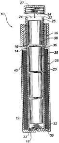
FIGURE 1 is side elevation view of a transmitter
constructed in accordance with the teachings of the present
invention.

DETAILED DESCRIPTION OF THE PREFERRED EMBODIMENT
The preferred embodiment, a transmitter generally
identified by reference numeral 10, will now be described with
reference to FIGURE 1.

With reference to FIGURE 1, the body of transmitter 10
includes a tubular housing 12 having an exterior surface 14.
An interior surface 16 and closed end 18 define an interior
cavity 20. An open end 22 provides an access opening 24. The
housing 12 is constructed from a ferromagnetic material such
as a low carbon steel. The exterior surface 14 of housing 12
at open end 22 is threaded 26. A detachable closure cap 27
threadedly engages threads 26 at open end 22 to close the
access opening 24. A electro-magnetic coil 28 is wrapped
around the exterior surface 14 of the housing 12. The housing
12 has transmitting electronics 30 which is also positioned
around the exterior surface 14 of the housing 12 adjacent to
electro-magnetic coil 28. The ferromagnetic housing 12 thereby
serves as a transmitter core for transmitter 10.


CA 02242390 1998-07-06
3

A first battery connection 32 is positioned at the closed
end 18 of the housing 12 and is insulated from the conducting
material of the housing 12 by means of an insulator disk 33.
A second battery connection 34 is positioned in the detachable
closure cap 27. A conductive circuit is completed by means of
the conductive housing 12 and wiring 36 connecting the first
battery connection 32, the electro-magnetic coil 28, and the
transmitting electronics 30 to the second battery connection
34. Batteries 38 positioned within interior cavity 20 of the
housing 12 supply power to the electro-magnetic coil 28 and
transmitting electronics 30.

A protective covering 40 composed of non-conducting
material such as a hard epoxy resin covers the magnetic coil
28, the transmitting electronics 30, and the exterior surface
14 of housing 12 except for the threaded area 26 of open end
22.

It will be apparent to one skilled in the art that
modifications may be made to the illustrated embodiment without
departing from the spirit and scope of the invention as
hereinafter defined in the Claims.

Representative Drawing
A single figure which represents the drawing illustrating the invention.
Administrative Status

For a clearer understanding of the status of the application/patent presented on this page, the site Disclaimer , as well as the definitions for Patent , Administrative Status , Maintenance Fee  and Payment History  should be consulted.

Administrative Status

Title Date
Forecasted Issue Date 2008-01-29
(22) Filed 1998-07-06
(41) Open to Public Inspection 2000-01-06
Examination Requested 2000-03-23
(45) Issued 2008-01-29
Expired 2018-07-06

Abandonment History

There is no abandonment history.

Payment History

Fee Type Anniversary Year Due Date Amount Paid Paid Date
Application Fee $150.00 1998-07-06
Registration of a document - section 124 $100.00 1999-04-09
Request for Examination $200.00 2000-03-23
Registration of a document - section 124 $100.00 2000-03-23
Maintenance Fee - Application - New Act 2 2000-07-06 $50.00 2000-05-08
Maintenance Fee - Application - New Act 3 2001-07-06 $50.00 2001-04-30
Maintenance Fee - Application - New Act 4 2002-07-08 $50.00 2002-06-26
Maintenance Fee - Application - New Act 5 2003-07-07 $75.00 2003-06-30
Maintenance Fee - Application - New Act 6 2004-07-06 $100.00 2004-04-20
Maintenance Fee - Application - New Act 7 2005-07-06 $100.00 2005-04-22
Maintenance Fee - Application - New Act 8 2006-07-06 $100.00 2006-04-18
Maintenance Fee - Application - New Act 9 2007-07-06 $100.00 2007-05-08
Final Fee $150.00 2007-10-31
Maintenance Fee - Patent - New Act 10 2008-07-07 $125.00 2008-04-24
Maintenance Fee - Patent - New Act 11 2009-07-06 $125.00 2009-06-25
Maintenance Fee - Patent - New Act 12 2010-07-06 $125.00 2010-04-20
Registration of a document - section 124 $100.00 2010-12-03
Maintenance Fee - Patent - New Act 13 2011-07-06 $125.00 2011-05-02
Maintenance Fee - Patent - New Act 14 2012-07-06 $125.00 2012-05-03
Maintenance Fee - Patent - New Act 15 2013-07-08 $225.00 2013-05-15
Maintenance Fee - Patent - New Act 16 2014-07-07 $225.00 2014-06-18
Maintenance Fee - Patent - New Act 17 2015-07-06 $225.00 2015-06-19
Maintenance Fee - Patent - New Act 18 2016-07-06 $225.00 2016-05-13
Maintenance Fee - Patent - New Act 19 2017-07-06 $225.00 2017-06-29
Owners on Record

Note: Records showing the ownership history in alphabetical order.

Current Owners on Record
WAVETRAK ELECTRONICS LTD.
Past Owners on Record
POWLOUSKY, PETER
WAVETRAK ELECTRONICS LTD.
Past Owners that do not appear in the "Owners on Record" listing will appear in other documentation within the application.
Documents

To view selected files, please enter reCAPTCHA code :


To view images, click a link in the Document Description column. To download the documents, select one or more checkboxes in the first column and then click the "Download Selected in PDF format (Zip Archive)" or the "Download Selected as Single PDF" button.

List of published and non-published patent-specific documents on the CPD .

If you have any difficulty accessing content, you can call the Client Service Centre at 1-866-997-1936 or send them an e-mail at CIPO Client Service Centre.


Document
Description 
Date
(yyyy-mm-dd) 
Number of pages   Size of Image (KB) 
Description 1998-07-06 3 112
Claims 1998-07-06 2 58
Representative Drawing 1999-12-29 1 13
Abstract 1998-07-06 1 12
Cover Page 1999-12-29 1 32
Drawings 1998-07-06 1 25
Drawings 2001-02-12 1 38
Claims 2001-02-12 3 117
Representative Drawing 2007-07-23 1 14
Cover Page 2008-01-04 2 45
Assignment 1998-07-06 2 64
Assignment 1999-04-09 2 94
Assignment 2000-03-23 2 93
Prosecution-Amendment 2000-03-23 1 31
Prosecution-Amendment 2001-02-12 5 187
Fees 2003-06-30 1 25
Fees 2005-04-22 1 24
Fees 2002-06-26 1 35
Maintenance Fee Payment 2017-06-29 1 33
Fees 2004-04-20 1 26
Fees 2006-04-18 1 25
Fees 2007-05-08 1 25
Correspondence 2007-10-31 3 101
Correspondence 2007-11-07 1 15
Correspondence 2007-11-07 1 17
Correspondence 2007-11-16 5 123
Fees 2008-04-24 1 27
Fees 2009-06-25 1 201
Fees 2010-04-20 1 26
Assignment 2010-12-03 3 165
Correspondence 2011-03-31 3 154
Correspondence 2011-05-31 1 11
Correspondence 2011-05-31 1 19