Note: Descriptions are shown in the official language in which they were submitted.
CA 02242421 1998-07-07
WO 9'7128295 PCT/CA97100065
TITLE OF THE INVENTION
METHOD AND APPARATUS FOR ELECTROLYSING LIGHT METALS
FIELD OF THE INVENTION
This invention relates to improved processes and apparatus for
the production of molten metals by electrolysis of their fused salts where the
metal is lighter than the electrolyte. More particularly, the invention
relates
to improved method and apparatus to collect molten metals such as lithium,
magnesium, or sodium in electrolytic cells of monopolar and multipolar
design.
BACKGROUND OF THE 1NVENTlON
All electrolytic cells that are used to commercially produce
lithium, magnesium or sodium utilize an electrolysis section above which the
electrolysis gas is collected, and a metal recovery section in which the metal
collects and is stored between tappings. Between the two sections is a
partition. As a common feature, this partition is usually immersed deep in
the electrolyte to effect good separation of the electrolysis gas and long
storage of the metal produced. This partition, sometimes called a curtain
wall or semi-wall, is a critical component of the cell due to the reactivity
of
the gas and/or the metal and the consequent need to maintain their
separation, but the partition is usually one of the components that limit the
operating life of a cell due to wear and cracking. The chemical wear of the
curtain watt in contact with the metal may be responsible for some loss of
product metal purity, and cracks in the curtain wall result in leaks of metal
and air into the electrolysis section with consequent oxidation of the
graphite
anodes and back reaction of the metal with the electrolysis gas.
CA 02242421 1998-07-07
WO 97/28295 PCT/C~~97100065
-2-
PRIOR ART
U.S. patent 1,501,756, issued 15 July 1924 to Downs,
describes a process commercially used to produce sodium from sodium
chloride. The process uses for the collection of the molten sodium an upper
reservoir which is separate from the electrolysis cell itself.
U.S. patent No. 3,396,094, issued 6 August 1968 to Sivilotti
et al., describes an electrolytic magnesium cell that is provided with a metal
collecting reservoir, located in the metal section and almost wholly
submersed in the electrolyte. The reservoir consists of an inverted box of
steel along the partition above openings through the curtain wall. The
reservoir is open along its bottom to receive the metal that comes through
the openings through the curtain wall. This metal collection arrangement
was superior to the prior art, where the metal was allowed to float freely on
the surface of the electrolyte. It allowed the cell to operate with the
electrolyte temperature near the melting point of the metal, which resulted
in substantial improvement of the current efficiency of the celE. The metal
had to be maintained molten to be tapped out of the cell by conventional
siphon means, and the fact that the metal was maintained under the surface
of the electrolyte equalized the two temperatures without need of
supplementary heating means. Relatively large quantities of metal were
collected and the need for undue frequency of tapping was avoiided.
It was subsequently found that oxidation of the residual floating
metal that escaped collection into the reservoir and hydroly sis of the
electrolyte were detrimental to the operation of the cell. Sludge formation,
short cell life and upsets in current efficiency were still experienced.
A fully enclosed cell provided with an insulating cover, with an
inert gas blanket and with internal temperature control means, was ,
developed as described in U.S. patent 4,420,381. The heat exchanger had
to be well insulated where it passed through the floating metal pad in order
to avoid premature freezing of the metal.
CA 02242421 2000-12-12
-3-
The design of U.S. patent 4,420,381 was an improvement over
the previous art and has been used with other more recent improvements in
cell design. These improvements are related to the use of new electrode
geometries, in particular those of multipolar design, that substantially
increase cell productivity and decrease unit energy consumption. These
improved cells are described in U.S. patents Nos. 4,055,474; 4,514,269;
4,518,745; 4,604,177 and 4,960,501 . These cells require an even tighter
control of the temperature and of the oxidation reactions. Also, they are
producing at a high rate so that the volume of metal to be stored in the metal
section between tappings is very large. Additionally, for good current
efficiency, the multipolar cells require an almost constant level in the
electrolysis section. This can be obtained by feeding the cells continuously
in response to level sensing means, or by regulating the supply of inert gas
to and from a submersed open-bottom reservoir, to compensate for liquid
volume changes when feeding and tapping are carried out intermittently.
In the cell described in U.S. patent 4,518,745 the electrolyte
circulation towards the metal section occurs sideways in the planes of the
inter-electrode spaces and over a weir, located inside the electrolysis
section,
downstream from the electrodes and upstream from the curtain wall. The
electrolyteimetal mixture flows over the weir so that the level above the
electrodes remains almost constant. However, the turbulence downstream
from the weir entrains residual gas within the electrolyte flowing into the
metal section. Also, the turbulence hinders coalescence of the metal that
would help its rising towards the floating metal pad.
Coalescence could be a significant factor to improve the current
efficiency of multipolar cells, as it is believed that droplets which are
smaller
than a critical size and are recirculated in the electrolysis section are
consumed by back reactions in the inter-electrode spaces Isee Sivilotti O.G.,
Operating Performance of the Aican Multipoiar Magnesium Cell, Light Metals,
1 17th AIME Annual Meeting, Phoenix, 1988). The critical size of
CA 02242421 1998-07-07
WO 97/28295 PCT/CA97/00065
-4-
the metal droplets depends on the degree of turbulence and on the path of
the circulating electrolyte. Therefore, the geometry of the metal section
where the metal separates by upwards settling is very important to obtain
high current efficiency. '
U.S. patent No. 5,417,8'i5, issued 23 May 7995 to Robinson
et al., describes the prior art for apparatus and methods to produce lithium
metal from molten mixtures of lithium chloride and other metal chlorides.
The patent describes a liquid metal skimmer based on the use of mechanical
propellers in a draft tube. Devices based on mechanical moving parts are
difficult to maintain in continuous reliable operation because of the high-
temperature molten-salt environment.
While satisfactory operation has been obtained with cells of the
prior art, the present invention is designed to obtain significant
improvements in such cells and in their method of operation. The main
objectives are a better current efficiency and improved yield and recovery of
purer metals, as well as greater convenience in the collection and removal
of the metal. Cheaper construction and longer operating life result in lower
capital costs and lower maintenance expenses.
SUMMARY OF THE INVENTI~N
It is an object of the present invention to provide a process to
electrofytically produce at high current efficiency lithium, magnesium,
sodium and other molten metal products that are lighter than the electrolyte.
Another object of the invention is to provide a process to
electrolytically produce reactive light metals of high purity.
A further object of the invention is to provide a method for
efficiently separating a fight metal from an electrolyte stream and for
facilitating its tapping at infrequent intervals.
A still further objective of the invention is to provide an
electrolytic cell of long life and of cost effective construction for the
CA 02242421 1998-07-07
WO 97/28295 PCT/CA97/00065
-5-
production of metals lighter than the electrolyte.
Thus in one broad embodiment the invention provides a process
for the production of a molten metal by electrolysis in an electrolytic cell
' comprising a process for the production of a molten metal by electrolysis in
an electrolytic cell having an electrolysis section, a metal recovery section
and a submerged reservoir, said process comprising electrolysing in said
electrolysis section of said cell an electrolyte containing a fused salt of
said
metal to produce said metal, said electrolyte having a greater density than
said metal, causing said metal and additional said electrolyte to circulate
continuously from said electrolysis section to said recovery section,
continuously separating said metal from said electrolyte in said recovery
section, causing said metal to circulate toward a part of said recovery
section remote from said electrolysis section, conveying said metal from said
recovery section to said submerged reservoir, and periodically recovering
said metal from said reservoir.
In a further broad embodiment the invention provides an
electrolytic cell comprising an electrolysis section, a metal recovery section
continuous with said electrolysis section, a submerged reservoir for storing
a product metal, and means for conveying a product of electrolysis from said
metal recovery section to said reservoir.
BRIEF DESCRIPTION OF THE DRAWINGS
The advantages of the invention will become apparent upon
reading the following detailed description and upon referring to the drawings
in which:-
Figure 1 is a vertical cross-section front to back through a cell
according to the invention;
Figure 2 is a plan view partly in section of the cell of Figure 1;
Figure 3 is a vertical transverse cross-section of the cell of
CA 02242421 1998-07-07
~_
_ _ ,._, "~
",
__ __ ~.,..,. "" """
w
-6-
Figure 1 ;
Figure 4 is a plan view partly in section of another embodiment of the
cell of Figure 1;
Figure 5 is a schematic cross-section of a transfer pump in position for
use in a cell according to the invention;
Figure 6 is a schematic cross-section through a part of a cell and a
syphon arrangement for use with the cells of the invention;
Figure 7 is a schematic vertical cross-sectional view of an apparatus
according to the invention;
Figure 8 is a schematic vertical cross-sectional view of the apparatus
of Figure 7;
Figure 9 is a schematic horizontal cross-sectional view of the
apparatus of Figure 7;
Figure 10 is a schematic view of a heat exchanger for use in the
electrolytic cell of Figures 7 to 9; and
Figure 1 1 is a vertical cross-section illustrating a further embodiment
of the invention.
DETAILED DESCRIPTION OF THE INVENTION
As is evident in the prior art, and in any event to those skilled in the
art, the invention is in the context of electrolytic cells which are divided
into
electrolysis and metal recovery sections which have conventionally been
separated by a partition or curtain wall. When the cell is in operation a
natural circulation is set up brought about by the liberation of gas in inter-
electrode spaces. As the gas rises, it functions as a pump to
CA 02242421 1998-07-07
WO 97!28295 PCT/CA97/00065
_ '7 _
set up circulation within the cell. Various means have been used to direct
the circulating stream along the upper part of the cell from the electrolysis
section to a metal recovery section and hence downward to the lower part
' of the metal recovery section and back to the lower part of the electrolysis
section under the electrodes. In the metal recovery section a floating metal
pad is formed and is tapped, generally on an intermittent basis. At an
appropriate point in the cycle the cell is fed to enrich the etectrolyte.
Two general criteria are required to obtain current efficiencies
that are as high as, or close to, those obtainable in electrolytic cells that
collect the metal at the cathode and keep it separate from the electrolysis
gas (as for example U.S. patent 3,396,094). First, the metal droplets that
are released in the inter-electrode space and are entrained in the circulating
electrolyte must spend the shortest possible time in the inter-electrode
space; and, second, the droplets must separate from the electrolyte into a
metal pad regardless of their small size. To meet the first criterion the
electrolyte is made to circulate as fast as possible in the inter-electrode
space and to meet the second criterion, notwithstanding the fast electrolyte
flow, means are provided to obtain coalescence and separation of metal
droplets before the electrolyte is returned to the bottom of the inter-
electrode
space.
Contrary to earlier belief, it has now been discovered that
coalesced metal droplets (and even a small metal pad) floating on the
surface of the electrolysis section do not contribute significantly to toss of
current efficiency, as a film of electrolyte coats the surface of the metal
and
prevents the direct contact between the metal and the electrolysis gas,
when good wetting conditions between metal and electrolyte are maintained.
Thus a partition or other structural barrier may not always be necessary to
maintain separation between the gas and metal.
To meet other obJectives of the invention, the separated metal
must be maintained out of contact with the refractory walls as much as
possible to prevent reaction with the latter and consequent contamination
CA 02242421 1998-07-07
WO 97/28295 PCT/Cps97/00065
_ g _
of the metal. This is to be obtained notwithstanding the desirability, for
efficient operation, of tapping as infrequently as possible the metal
produced.
The fact that the reaction between the refractory walls and the
metal is prevented and the fact that the cell is sealed to eliminate metal
oxidation and electrolyte hydrolysis are further requirements to obtain high
current efficiency,
high yields and long operating life.
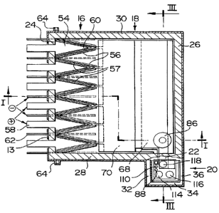
In reference to Figures 1 to 3, the apparatus illustrated is an
electrolytic cell 10 having a structural steel casing 12 lined with a tayer of
insulating and refractory material 14 suitable to contain a molten salt
electrolyte. The cell 1 O is divided into an electrolysis section 16, a metal
recovery section 18, and a services section 20, the last separated from the
other sections by a semi-wall, partition, or curtain wall 22.
Cel! 1 O comprises back waft 24, front wall 26 and side walls 28
and 30. In one preferred configuration the partition wall 2:2 extends
diagonally across the front corner of cell 10 from front wall 26 to side wall
28 (or 30).
In a further and most preferred configuration the services
section 20 is external to cell 10 and is defined by a set of side walls 32, 34
and 36. In this configuration the partition wall 22 comprises a part of side
wall 28 of cell 10.
The cell 1 O is provided with top 38 which may be in sections
for convenience of handling and which seals the cell, including the services
section 20, when the cell is in operation. The partition wall 22 is preferably
integral with a section of top 38 and extends downwardly a short distance
below surface 40 of electrolyte 42 to thereby seal services section 20
against entry into that section of electrolysis gas liberated into space 44
between surface 40 of electrolyte 42 and top 38 of cell 10.
Below surface 40 of electrolyte 42 and below the bottom 46
of partition wall 22, the services section 20 is open to electrolyte 42 in
cell
CA 02242421 1998-07-07
WO 97!28295 PCT/CA97/00065
-g_
10.
. The electrolysis gas disengages from the electrolyte at top 48
of the electrodes 50 and is collected under the refractory-lined cover 38.
- The gas is withdrawn under slightly negative pressure through a gas duct
schematically shown by the arrow 51.
The arrow 52 indicates the location of feed entry into the cell
through refractory-lined lid 38 when the cell is to receive solid feed.
In the preferred arrangement, the anodes 54 and cathodes 56
are disposed along the back wall 24 of cell 1 O and provide facing surfaces
for the electrolysis process. One or more bipolar electrodes 57 is (are)
interposed between anode and cathode when a multipoiar structure is used.
The gas generated on the anodic surfaces provides the pumping action to
the electrolyte as the gas rises in the inter-electrode spaces. The
electrolyte
carries entrained metal droplets with it.
As shown in the horizontal views of Figure 2 and 4, the anodes
are preferably wedge shaped, with decreasing cross-section outwardly from
back wall 24, thus pointing toward the front of the cell, while the cathodes
are opposite. The anodes are preferably though not necessarily pointed.
This geometry is more advantageous when the anode leads 58
are mounted through the back wall 24 of cell 1 O, as the current flows in the
body of the anode at uniform current density from the root of the anode to
the pointed end 60. The cathode leads 62 are also mounted through the
back wall 24 of cell 10, preferably through the bottom part of wall 24, in
order to reduce the danger of short-circuits through the electrolyte-wetted.
refractory lining. The lining may be rapidly destroyed by such event.
Alternatively, to further reduce this danger, the cathode leads may be
- mounted through the bottom of the cell 10, but the connection to the
cathode busbar will be more difficult. For electrical insulation reasons, both
the anode and the cathode leads 58 and 62 are isolated from the cell casing.
As an additionat precaution, part 63 of the casing 12 that surrounds the
anode leads 58 is electrically insulated from the rest of casing 12 by spacers
CA 02242421 1998-07-07
WO 97/28295 PCT/CA,97I0006S
- 10-
64.
The electrolyte/metal mixture flows along the cathode 56
toward the front of cell 10. The wedge-like geometry of the cathode is
particularly useful in providing to the electrolyte a linearly increasing
cross-
sectional area that matches the increasing votume of the electrolyte
discharged along the tap of the cathode. In this way, after the discharge,
the turbulence is minimized and the metal droplets entrained in the
electrolyte start to coalesce immediately. The space between the non-
working faces of the cathode may be filled with a set of metallic nets or
other conventional means to help the metal coalescence.
Contrary to earlier cells, it must be understood that the
electrolyte flow velocity is slowed while still in the electrolysis section,
by
reason of cell geometry, so coalescence, as indicated, begins in the
electrolysis section.
An important aspect of the invention is the continuity between
the metal recovery section 18 and the electrolysis section 16, 'the former
extending to the front wall 36 of cell 1 O. Leaving the electroly sis section
and in the metal recovery section 18, the electrolyte flows ai: very low
velocity, so that the time for the metal droplets to separate from the
electrolyte is maximized.
A bottom wall 66 of metal recovery section 18 forms the
sloping roofs of two open-bottom reservoirs 68 and 70, which are set in
cascading and sealing sequence along the return flow path of the Electrolyte
in the tower part 67 of cell 1 O. Reservoir 68 provides storage capacity for
the metal produced between tapping cycles; and reservoir 70, for the inert
gas required to compensate for volume changes during intermittent tapping
and feeding operations. '
Reservoir 68 is an open-bottom steel box that runs along the
front wall 26 preferably in sealing abutment with the side rivalls 28 and 30
.. and front wall 26. it is supported on a ledge 74 along wall 26 and on
similar
ledges on the side walls 2$ and 30 of the cell. Reservoir 70 i s similarly
CA 02242421 1998-07-07
WO 97128295 PCT/CA97/00065
- 11 -
supported in sealing abutment on the front end of the cathodes at 76 and
on ledges on the side walls 28 and 30. Reservoir 68 is sufficiently heavy to
stand firm on its supports, while reservoir 70 should have adequate ballast
' to keep it in place when full of inert gas.
Reservoirs 68 and 70, as well as heat exchanger 78, are
located below the curtain wall 22 and preferably extend into services section
20. When those components must be removed for maintenance, curtain
wall 22 must also be removed. Therefore curtain wall 22 is preferably
attached to the front section 80 of the cell lid, as noted above. To minimize
this problem, more efficient heat exchangers can be used, based on
thermosyphon and/or heat pipe designs of simple vertical or gently curved
pipe geometry which can be extracted from cell 1 O through services section
20 without removal of cell lid 80 or curtain wall 22.
Figure 4 shows a transverse curtain wall, while Figure 2 shows
a diagonal geometry. The transverse curtain wall is preferred as the width
is smaller and can be built of a single refractory block that can be handled
independently. However, in either case, the front wall 26 ~ of the cell 10
remains straight, and, preferably, a series of cells are operated from a
platform running along the front of the cells.
The means for conveying metal into reservoir 68 preferably has
entry funnel 82 at surface 40 of the electrolyte 42 in the metal recovery
section, where the metal collects naturally. There are two preferred means
of transfer: an active pump 84 or a skimmer-tube 86. A selection is made
depending on the relative density of the metal and the pressure head
available. A large hydraulic head is required to force a light metal down into
a skimmer-tube, and, therefore, in lithium cells of monopolar design, it is
' best to use a transfer pump. The opposite is true for magnesium cells of
multipolar design where the gas-lift action is strong and the relative metal
density is only about 10%. In this case the electrolyte flow through the
skimmer-tube could be only a fraction of the total flow, and leaks around the
reservoirs can be tolerated.
CA 02242421 1998-07-07
WO 97/28295 PCT/CA97/00065
-12-
Mathematical and/or physical modelling techniques are used to
design the skimmer-tube 86. A good reference is a paper by R.
Sankaranarayanan and R.I.L. Guthrie entitled: Vortex Suppression Device
Improves Steel Cleanness, 1995 - 14th PTD Conference Proceedings of the
iron and Steel Society. A vortex phenomenon (that is stated to enhance
entrapment of the floating slag) may be encouraged in the present invention
by locating skimmer-tube 86 away from the centre of symmetry of the cell.
The level of electrolyte over the entry funnel 82 and the hydraulic pressure
drop through the tube itself is controlled by using level sensing means 88
and feeding or bleeding inert gas into and out of reservoir 70. Level
fluctuations of the order of about one centimetre are acceptable for
satisfactory performance.
Where a pump is required or desired, conventional roitary pumps
may be used. However, a transfer pump design that meets the tough
environmental conditions of a fused salt electrolytic cell is described
schematically in Figure 5. The body of the pump is a vertical tube 90
partially immersed in the electrolyte and located in the services section 20
out of contact with the electrolysis gas. The bottom of the tube is
connected via a non-return valve 92 to the entry funnel 82 and to a bottom
discharge nozzle 94, via another non-return valve 96. The non-return valves
cause the flow to occur only in the direction from the entry funnel 82 and
to the bottom nozzle 94 respectively. The top 98 of the tube 90 is
connected to an inert gas supply via a pressure reducer 100 and a non-
return valve 102. Between the non-return valve 102 and tube 90, a,
pneumatic accumulator 104 is connected to the inert gas line 106. The
bladder 108 of accumulator 104 expands or contracts, depending on
whether compressed air is fed into or bled out of the accumulator via three-
way valve 109. By periodically switching the three-way valve with
r
solenoids, inert gas is caused to be moved, in known volumes, in .and out of
the tube 90, causing intermittent flow of liquid in alternating directions
through its bottom connection. Thereby the volume is known of f6uid
CA 02242421 1998-07-07
WO 97/28295 PCT/CA97/00065
-13-
transferred from the surface of the electrolyte in the metal recovery section
to the region below the metal collecting reservoir 68. By selecting a
frequency of operation that matches the volume of metal production, the
' size of the metal pad that forms at the entry funnel between pump cycles is
maintained at an acceptable level. Preferably, the rate of pumping is
maintained higher than the rate of metal production and the fluid flow in the
transfer pump is a mixture of metal and electrolyte, with the tatter making
up for the differences.
As well, a parallel path is provided for electrolyte circulation,
and this may fottow several paths. For example, openings may be provided
in the bottom wall 66 of metal recovery section 20, circulation may occur
through section 20 under wall 22, etc.
The transfer pump 84 is mounted on the refractory and
insulating lid 38 of the services section 20 in such a way that it can be
installed and removed for maintenance reasons without removal of the lid 38
or of the curtain wall 22. All the equipment on lid 38 is installed by means
of gas-tight flanges so that during operation a slight positive pressure of
inert gas can be maintained in space 45.
In order to access cell 10 without exposure to the electrolysis
gas in space 44, various entry points are provided into services section 20.
Thus, temperature and level sensing means 110 and 88, and heat exchanger
inlet and outlet 114 and 1 16 are preferably located in services section 20.
A tapping spout 1 18 is also located in services section 20 and extends into
reservoir 68 to provide access to the reservoir for tapping the product metal.
Where a transfer pump is utilized, as discussed above, as a means of
conveying product from the metai recovery section to reservoir 68, the pump
' is also preferably located in services section 20.
In commercial operation, cells of the present invention will be
used as part of a bank of multiple such cells. The molten metal can be
tapped from reservoir 68 by conventional means, such as syphons attached
to vacuum ladles moved to and from the cell by truck on the operating
CA 02242421 1998-07-07
WO 97/28295 PCT/C~97/OOObS
- 14-
platform conventionally present on the front of the bank of cells.
Alternatively, the ladles may be moved by mobile overhead crane.
However, it has been found very advantageous to provide each
cell 1 O in a bank of cells with metal tapping means connected directly to a
hot metal piping system leading from the cells to the cast-house. Preferably
a pipeline Z 20 is located along the front of a series of cells below the
operating platform. Pipeline 120 is preferably thermally insulated and is
made up of thermostatically controlled modules in a closed loop network in
such a way as to secure continuous operation of the cells even when a pipe
module must be isolated from the pipeline loop and rennoved for
maintenance.
in order to avoid short-circuiting between cells, the tapping
must be performed on a cell by cell basis. When a cell is discharging metal
into the pipeline 120 during tapping, a direct electrical connection is set up
by the molten metal between the cell and the pipeline so that trte pipeline
rises to the potential of the cell being tapped, while the rest of the cells
are
electrically insulated from the pipeline.
The tapping means in each cell 10 preferably consists of a
syphon,pipe 122 with a leg 124 immersed in the tapping spout 118 just
below the level of the electrolyte. A second leg 126 is immE:rsed in a
downstream trap 128, the liquid level in which is just above the level of
electrolyte in cell 1 O. The lower metal density causes the metal level in the
tapping spout 1 18 to be higher than the level in the trap and thus enables
the syphon, when primed, to discharge metal from cell 1 O to pipeline 120.
Preferably, when the syphon is not in use, it is connected to an
inert gas supply which maintains a slight positive pressure in the syphon to
avoid ingress of air.
Similarly, electrically and thermally insulating lids 130, 132 and
134 are provided to seal the top of the tapping spout 1 18, the trap 128 and
the entry 136 to the pipeline 120. The spaces below the lids are at all times
CA 02242421 1998-07-07
WO 97/28295 PCTlCA97/OOfl65
-15-
supplied with inert gas at slightly positive pressure to avoid oxidation of
the
metal.
To initiate a tapping procedure, the application of vacuum at the
top of the syphon causes the metal to move up leg 124 of syphon 122 to
the top of the teg 124 and hence into leg 126 to initiate flow. The level in
the downstream trap in the syphon is located just above the electrolyte level,
so that the flow is maintained through the syphon only if there is metal in
the submerged reservoir 68. When the reservoir is empty of metal, the flow
will naturally stop, even if the syphon is still primed by the vacuum line.
This system preferably includes a pre-set time of operation of the syphon,
after which the vacuum line is switched off and the inert gas line activated.
In good operational practice the syphon is preferably pre-heated
to operating temperature, prior to initiating the tapping sequence.
With reference to the embodiments of Figures 7 to 1 1, a
process and apparatus are shown in which the partition wail 22 is moved to
a position between the electrolysis section and the metal recovery section,
thus incorporating the services section into the metal recovery section, while
still maintaining both the gas seal for services piping and the desired flows
between the electrolysis section and the metal recovery section.
The apparatus illustrated in these figures is an electrolytic cell
210 having a structural steel casing 212 lined with a layer of insulating and
refractory material 214, suitable to contain a molten salt electrolyte. The
cell 210 is divided into an electrolysis section 216 and a metal recovery
section 218, separated by a semi-wall, partition, or curtain wall 220.
In a preferred configuration and for reasons to be discussed
below, the cell includes a second partition wall 222 adjacent to partition
wall
220 but separated therefrom by the space 224. A conduit 225 leads from
space 224 through the top wall of cell 210.
in conventional arrangement, electrolysis section 216 is located
adjacent back watt 226 and metal recovery section 218 is located adjacent
front wall 228 of cell 210.
CA 02242421 1998-07-07
WO 97!28295 PCT/CA~97/00065
-16-
With reference to electrolysis section 216, electrical leads 230
pass through back wall 226 and are connected to cathodes 234. Cathodes
234 are normally steel.
Similarly, electrical leads 236 pass through top wall 238 of
electrolysis section 216 and are connected to anodes 242. Anodes 242 are
preferably of graphite.
In a modern multipolar cell, bipolar electrodes 244 are tocated
between anodes 242 and cathodes 234 and each bipolar electrode 244 acts
as cathode on one face and anode on the other face, so that the electrolysis
process is multiplied by the number of inter-electrode spaces operated within
one cell.
With reference to the metal recovery section 218, that section
preferably contains an open-bottom reservoir 246 which is partially open at
gate 248 to electrolyte 250. Reservoir 246 includes inlet/outiet 252 for
injection or removal of inert gas.
As is discussed later, it is essential to control the level of
electrolyte 250 within cell 21 O. That level can be controlled by injecting
gas
through inlet/outlet 252 to force liquid from reservoir 246 to raisE: the
level
of electrolyte 250 within the cell 210 or gas can be withdrawn from
reservoir 246 to permit the flow of electrolyte 250 into reservoir 246 to
thereby lower the level of electrolyte 250 in cell 210. The use of an open
bottom reservoir for purposes of level control i conventional in -the art.
Metal recovery section 218 also includes a submerged metal
recovery reservoir 254. Reservoir 254 is provided with an entry weir 256,
the function of which will be described below, and a port 258 through top
wall 260 of metal recovery section 218 through which molten metal 262 in
reservoir 254 can be tapped.
Metal recovery reservoir 254 is separated from front wall 228
by space 264. Also located within metal recovery section 218 are at least
two horizontal baffles 266 and 268. In the most preferred configuration,
and, as illustrated, the baffles are comprised of the tubes 270 of a heat
CA 02242421 1998-07-07
WO 97/28295 PCT/CA97/00065
-17-
exchanger 272.
. As illustrated in Figure 1 O, heat exchanger 272 comprises inlet
274, outlet 276 and manifolds 278, together with the aforementioned tubes
- 270.
Reverting back to Figures 7 to 9, a horizontal partition 280
extends between cathodes 234 and a wall 282 of reservoir 254 to form a
trough 284.
A second horizontal partition 286 extends from cathodes 234
to a position adjacent tubes 270. Adjacent the baffle 266 a short refractory
partition 288 extends from front wall 228 to a position adjacent baffle 266.
Baffle 268 is separated from front wall 228 by space 290.
The various structural members in the two sections define flow
paths which will be discussed below.
In operation of the cell, electrolysis gas, usually chlorine, is
generated on the anodic faces and metal is deposited in liquid form on the
cathodic faces. Electrolysis gas in the inter-electrode spaces lifts the
electrolyte toward the top of electrolysis section 21 f, where the gas/iiquid
phases separate. The gas passes into the space 292 at the top of
electrolysis section 216 and is removed therefrom. The gas is preferably
removed under a slightly negative pressure to prevent escape.
The upward movement of the electrolysis gas in the inter-
electrode space drives the circulation of the electrolyte through the cell.
Driven by the rising gas, the etectrolyte 250 circulates toward
the top zone 306 of the metal section 218, passing under the semi-wall 220,
which is usually, as noted above, of refractory construction to resist the
corrosive action of the electrolysis gas. The semi-wall is preferably built as
a tight sequence of firebrick blocks anchored to the steel shell 307 of cover
309 of the cell 21 O, but could also be supported from the floor by refractory
or steel piers (not illustrated) or be an arch structure (not illustrated)
supported by the sidewalls of cell 210. The refractory material may
preferably be made of acid resistant firebrick or of fused alumina or of glass-
CA 02242421 1998-07-07
WO 97/28295 PCT/CA,97/00065
_ 18 _
ceramic materiaB such as PYROCERAM 9606 T"" cordierite as described in
U.S. patent 5,429,722.
One important aspect of this embodiment of the invention is
that the semi-watt 220 does not go deeply into the electrolyte 250, not to
unduly impede the circulation of the electrolyte towards the top of the metal
section, as occurs in the cells of the prior art. One important function of
the
separating wall in the prior art was to contain the metal accumulating in the
metal section between tappings. A deep metal pad floating on electrolyte
250 was required also to facilitate tapping by siphon. However, when the
metal pad is deep, the liquid metal being lighter than the electrolyte has the
tendency to pass through cracks or holes or open joints in the separating
wall, and to return to the electrolysis section where it back-reacts with the
electrolysis gas.
In the present case, as discussed below, a deep metal pad is
~t ~~w..w.w..l .-_I .- J.L _
IIVL IVIIIIGU, amu so me only function of the semi-wall of the present
invention is to seat the gas zone 306 at the top of the electrolysis section
216 where the gas readily separates from the electrolyte due to its much
lower density.
To prevent carry-over of the residual gas to the metal section
by the circulating electrolyte, the second semi-wall 222 can be provided,
following the semi-wall 220. A slightly positive pressure of inert gas is
maintained in the metal section. The residual gas is released against the
bottom 221 of semi-waN 220 and makes its way into the space 224
between the two semi-walls. This gas is then vented out together with
some inert gas that leaks through the semi-wall 222 (because of cracks or
of its natural porosity), making the metal section 218 free of electrolysis
gas. The second semi-wall 222 can be of the same refractory material, as
shown in Figure 7, or of metallic material, depending on the corrosive
conditions and the quantity of residual electrolysis gas prevailing in the
space between the semi-watts. Vent conduit 225, if desired, is connected
to gas scrubbing apparatus (not shown) designed to absorb the: residual
CA 02242421 1998-07-07
WO 97/28295 PCT/CA97/00065
- 79 _
electrolysis gas before release to the atmosphere.
To further prevent the carry-over of residual electrolysis gas into
the metal section by the circulating electrolyte, the liquid velocity under
the
- semi-wall is reduced by the deep trough 284 located along the semi-walls,
into which the semi-walls themselves are slightly immersed. With
suspended semi-walls that are not supported from the bottom, the velocity
of the electrolyte is minimized relative to the velocity in the turbulent zone
308 above the electrodes, as the total width of the cell is made available to
the electrolyte flow, and therefore the electrolyte velocity and the gas carry-
over is reduced to a minimum. The carry-over of metal droplets, however,
is still active, because the small density difference between metal and
electrolyte favours the entrainment, and because the metal droplets are still
very small as the metal did not have a chance to fully coalesce in the
turbulent zone 308 above the electrodes.
The design of the trough 284 for optimum performance of the
gas/electrolyte separation and of the electrolyte/metal carry-over functions,
could be carried out following the research techniques described in the AIME
paper referred to above. The electrolyte flow path that is made possible by
the novel geometry of the semi-wails 220/222 and of the trough 284 of this
invention affords a reduced turbulence of the electrolyte in this critical
zone
under the semi-wall and, therefore, an early onset of coalescence of the
metal droplets. The other advantageous feature afforded by this aspect of
the invention is the fact that the streamlined flow of the electrolyte reaches
the very surface of the metal section where metal separation coalescence
naturally occurs resulting in increased metal collection efficiency.
In the preferred case, for the sake of more reliable sealing and
better stability of liquid level 310 in the electrolysis section 216 above the
electrodes 234/244, is located an overflow weir 312 downstream from the
trough 284. The geometry is chosen to reduce the turbulence due to this
weir to a minimum. The trade-off is between the advantage of increased
reliability of the gas seal and increased control of the bypass current on top
CA 02242421 1998-07-07
WO 97/28295 PCT/C~97/00065
-20-
of the bipolar electrodes; and the loss of some metal coalescence and
separation because of the increased electrolyte velocity over the weir, but
this loss can be minimized by round-shaping the cross section of the weir
itself, as it is conventionally practiced in overflow weirs used i.n spillways
and in other large-scale water works.
As illustrated in Figures 7 and 8, weir 312 is conveniently
formed as the top wall 247 of reservoir 246. The upstream and downstream
sides 243 and 245 respectively of top wall 247 can be individually profiled
to promote smooth flow up to and over the weir 246.
The top of weir 312 may be typically O to 2 inches above the
level of the bottom 221 of partition walls 220/222. The concern is that the
electrolyte level behind the weir be such as to maintain bottom 221 of
partition walls 220/222 submerged to effect a good seat between sections
216 and 218 above the electrolyte.
The electrolyte flow over the weir 312 is preferentially stronger
at the two ends of the trough to effect a flow from the centre to the ends
of the trough and a sweeping flow pattern, past the weir, towards the centre
of the free surface of the electrolyte in the front section. The weir can be
profiled with a higher central section sloped toward lower ends, to achieve
this objective. Also the spaces 313 (Figure 0) between the ends 31 1 of the
weir 312 and the side walls 227 of the cell 210 favour the flow of additional
electrolyte at the two sides of the metal section 218.
In a preferred configuration the forward face 255 of recovery
reservoir 254 is somewhat concave toward weir 256 so that space 264 is
somewhat greater in that area. The resulting increase in flow will also tend
to draw the electrolyte stream toward the area of weir 256 and so to
establish metal pad 318 in that area.
At a convenient location along the trough, a feeding apparatus,
schematically indicated with the downward pointing arrow 314, supplies
solid feed at controlled rates to the cell 210. The trough 284 is sufficiently
large to effect rapid dissolution of the feed into the electrolyte without
CA 02242421 1998-07-07
WO 97/28295 PCT/CA97/00065
-21 -
accumulation of solids on the bottom of the trough. The feeding apparatus
314 is sealed and pressurized with inert gas.
Alternatively, liquid feed as discussed later may be utilized.
The electrolyte flow is then directed towards the metal
discharge weir 256 which is located as far as possible from semi-wall
220/222, usually at the centerline of symmetry (in plan view) of the cell, and
slightly above the liquid level 316 in metal recovery section 218 downstream
of weir 312. The separated metal is carried by the electrolyte 250 towards
the weir 256 which is therefore surrounded by a metal pad 318 floating
above the flowing electrolyte 250 and waiting to be discharged. In
proximity to the weir 256 a metal detector 320 is positioned to detect the
presence of metal floating on the electrolyte surface. Any type of metal
detector or sensor can be used, but it is advantageous to use simple electric
contacts, such as those used in wet bulb thermostats for the operation of
domestic heating furnaces where the start/stop cycles of the furnace are
activated by the contact between a mercury drop and a solid metal probe
when the mercury drop moves into and out of contact with the probe by the
action of the thermostat. Similarly, in the process of the present invention,
the metal discharge cycles are partly controlled by the detector 320.
Preferably, the initiation of the metal discharge cycle is
controlled by a clock that, at frequent intervals, starts a level rising
routine,
either by increasing the rate of feeding (when continuous feeding is
practiced) by the feeding device 314, or by feeding inert gas into submerged
open-bottom reservoir 246 shown in Figure 7. The increased electrolyte
level causes the metal to overflow into submersed closed-bottom metal
recovery reservoir 254, and the floating metal pad 318 becomes smaller and
smaller until the detector 320 detects the absence of metal in its location
and stops and reverses the level rising cycle. Detector 320 is preferably
spaced from weir 256 so that when detector 320 stops the level rising
cycle, there will be some metal pad remaining adjacent weir 256 and the
level will not have been raised to the point where electrolyte flows into
CA 02242421 1998-07-07
WO 97/28295 PCT/CA97/00065
-22-
reservoir 254. If desired for increased reliability of operation, deaector 320
is provided with two electrical contacts: the first to stop the level rising '
routine and the second to protect from accidental mis-operation of the
system. After several discharge cycles the reservoir 254 becomes full and
a tapping cycle must be performed through tapping port 258 before the
capacity of the crucible is exceeded. To avoid overfilling, a second metal
sensor 322 is preferably installed in reservoir 254. The sensor can be of the
same design as sensor 320 and its function is to send a visual or audible
alarm to the operator, so that he will attend to the tapping of the cell as
soon as practically possible.
Typically, the tapping cycles are performed in intervals of
several hours, while the clock cycles can be set at intervals of several
minutes, depending on cell productivity. The actual metal discharge time
could be several seconds, depending on the level control strategy being
used. The level upset during metal discharge will only introduce a small
disturbance to the cell operation and its effect on average cell performance
wilt therefore be negligible.
The flow of the electrolyte 250 is now directed downwards
towards a secondary settling zone 324 in the metal section 228, where the
small metal droplets that have not coalesced and separated at the surface
are recovered before they are recycled with the electrolyte 250 to the
electrolysis section 216. The settling zone is designed to make the
electrolyte meander horizontally between baffles 266 and 268 which are
uniformly spaced to provide quiet paths for the electrolyte to release its
residual metal droplets towards the ceiling surfaces of the baffles. Once the
metal is separated from the electrolyte 250, it is easy for it to rise towards
the free surface in the metal section and join the floating metal pad 318.
The baffles 266 and 268 can take any convenient form. Where steel plates _
are used, drain holes are appropriately located in the baffle plates to allow
droplets to rise.
Alternative arrangements, conventionally found to bE: effective
CA 02242421 1998-07-07
WO 97/28295 PCT/CA97/00065
-23-
in enhancing coalescence, can be used for the secondary recovery of the
metal droplets. For example, an array of metal channels or inverted troughs
can be positioned along the electrolyte flow path, always with the view to
reduce turbulence, reduce the settling distance and in general provide
additional settling surfaces for the metal droplets. Such arrangements are
known in the art and are extensively used for example in oil/water separation
devices. Following that practice, it may be found convenient to arrange the
baffles 266 and 268 as parallel plates uniformly spaced and have the
electrolyte flow disposed between them in parallel streams, all directed
towards the electrolysis section, without departing from the spirit of the
invention.
In Figures 7 to 10 a cell design according to the invention is
shown where the baffle plates 266 and 268 are in the form of arrays of
pipes or tubes 270 which are used as heat exchange surfaces. This design
is particularly effective in a cell 210, such as that illustrated, where the
cell
walls comprise a steel casing 212 lined by refractory walls 214 suitable to
contain the electrolyte, as compared to cells where the electrolyte is
contained in a metallic crucible that can be heated or cooled externally as
the case may be. The heat exchanger 272 shown in three dimensional view
in Figure 1 O is installed in the metal section 218 and is provided with entry
and exit pipes 274 and 276 that pass through top wall/cover 309 of cell 210
and with manifolds 278. Cold air is forced through the heat exchanger 272
to cool the cell 21 O to its operating temperature and, if desired, hot air
can
be used to boost the temperature up, according to the practice described in
U.S. patent 4,420,381. The new geometry affords a more efficient heat
transfer and the combination of the heat transfer function with the flow
streamlining function to enhance metal coalescence is a useful part of the
present invention. The entry and exit pipes 274 and 276 do not need to be
insulated because they can be located away from where the metal pad 318
is usually floating, avoiding as such the problem of metal freezing in contact
with the pipes.
CA 02242421 1998-07-07
WO 97/28295 PCT/CA97/00065
- 24 -
The cell shown in Figure 11 describes an alternative
embodiment of the invention that uses a submersed open-boittom metat
recovery reservoir 330 which performs the same metal storing function as
reservoir 254 in the previous embodiment. This is particularly effective
when the metal is only slightly less dense that the electrolyte, which is the
case for example for magnesium. In this case the operating principle used
for the metal collection is to sweep away the metal pad 318 that tends to
form on the surface of the flowing electrolyte and drag the mietal down
through the space 264 between the reservoir 330 and the front wall 228 of
the metal section 218. In this embodiment the reservoir 330 is dosed at the
top centre and the weir 256 is absent. Tapping port 258 is still present.
The metal separates from the electrolyte below the reservoir and is collected
inside the reservoir through the open bottom 332 of the reservoir 330 itself.
The mesa! accumulates inside the reservoir and is siphoned out from it at
infrequent intervals in the conventional manner through tapping port 258.
In this embodiment electrolyte flow is not encouraged to stream
toward the centre front of metal section 218, but preferably flows evenly
over reservoir 330 across its width.
To facilitate the flow of metal in the Figure 1 1 embodiment, the
upwardly sloped top 340 of reservoir 330 leads to increased flow velocity.
Further, space 264 between reservoir 330 and front wall 228 of cell 210 is
preferably reduced. Lo~iver front edge 342 of reservoir 256 is preferably
rounded and bottom wall 344 of reservoir 256 is preferably sloped upwardly
toward open bottom 332 of reservoir 256. These preferred structural,
features all facilitate the movement of metal into the reservoir. Metal pad
346 then forms within reservoir 330 floating on electrolyte 348.
The cells shown in Figures 7 and 1 1 contain features that are
desirable for intermittent feeding operations such as are used when molten
feed is transported to the cell in crucibles or the like. The electrolyte
volume
decreases between feedings, and a compensating device in the form of a
submerged open-bottom reservoir 246 is required to control the liquid level
CA 02242421 1998-07;07 " "
.~ . .~ , . . ,
. ~ . . : ; , ,.
. . . ... , ,
. ~. ,
.. '.. ,. , ,, ,,
-25-
at the desired set point for optimum operation. The open-bottom reservoir
246 is supplied with controlled amounts of inert gas to compensate for
~'i
electrolyte volume changes between feedings. This device is the same as
provided in the prior art for the same function. The only difference is that
reservoir 246 in the case of the embodiment shown in Figures 7 to 9 does
not need to be operated during metal tappings, as in the prior art and as in
the embodiment of Figure 1 1 . Importantly, in the present invention,
reservoir
246 can be used in the embodiment of Figures 7 to 9 to cycle the liquid level
at pre-set time intervals to effect the metal discharge into reservoir 254 as
previously described.
When the cell is fed with molten feed, it is usually done by openly
discharging it into the metal recovery section. To avoid exposure of the main
electrolyte surface to ambient air which reacts with the electrolyte and metal
during the feeding operations, the metal recovery section 218 is maintained
sealed in inert gas by providing the feed port 334 with a standpipe 336 (see
Figure 8) that acts as a seal when the lid 338 is open during feeding. When
the lid 338 is closed, inert gas is fed to the metal section 218 (to maintain
its slight positive pressure) via the feed port 334, so that the standpipe 336
is filled with gas and therefore no metal accumulates inside it. For added
' freedom from freezing problems, the feeding port 334 is located away from
the metal pad 318 floating on the electrolyte.