Language selection

Search

Patent 2242539 Summary

Third-party information liability

Some of the information on this Web page has been provided by external sources. The Government of Canada is not responsible for the accuracy, reliability or currency of the information supplied by external sources. Users wishing to rely upon this information should consult directly with the source of the information. Content provided by external sources is not subject to official languages, privacy and accessibility requirements.

Claims and Abstract availability

Any discrepancies in the text and image of the Claims and Abstract are due to differing posting times. Text of the Claims and Abstract are posted:

  • At the time the application is open to public inspection;
  • At the time of issue of the patent (grant).
(12) Patent Application: (11) CA 2242539
(54) English Title: ROTARY PIPE CONNECTOR
(54) French Title: RACCORD ROTATIF DE CONDUITE
Status: Deemed Abandoned and Beyond the Period of Reinstatement - Pending Response to Notice of Disregarded Communication
Bibliographic Data
(51) International Patent Classification (IPC):
  • F16L 27/08 (2006.01)
  • F16L 37/20 (2006.01)
  • F16L 37/23 (2006.01)
(72) Inventors :
  • MAAS, MARLIN (United States of America)
(73) Owners :
  • KURIYAMA OF AMERICA, INC.
(71) Applicants :
  • KURIYAMA OF AMERICA, INC. (United States of America)
(74) Agent: ROBIC AGENCE PI S.E.C./ROBIC IP AGENCY LP
(74) Associate agent:
(45) Issued:
(22) Filed Date: 1998-08-20
(41) Open to Public Inspection: 2000-02-20
Availability of licence: N/A
Dedicated to the Public: N/A
(25) Language of filing: English

Patent Cooperation Treaty (PCT): No

(30) Application Priority Data: None

Abstracts

English Abstract


A rotary pipe connector includes a first connector member
fastened to a liquid reservoir fitting, a second connector member
fastened to a liquid delivery means and inserted into the first
connector member, a plurality of steel balls inserted through a
radial screw hole at the first connector. member into matched
annular ball grooves between the inside wall of the first connector
member and the outside wall of the second connector member to
secure the first connector member and the second connector
member together, for permitting the second connector member to
be rotated with the liquid delivery means in the first connector
member, and a screw rod threaded into the radial screw hole to stop
the steel balls in the annular ball grooves.


Claims

Note: Claims are shown in the official language in which they were submitted.

What the invention claimed is:
1. A rotary pipe connector comprising
a first connector member fastened to a liquid reservoir
fitting. said first connector member comprising an inside wall
defining an axially extended center through hole, an inside annular
flange raised around the inside wall within said center through hole,
an annular ball groove provided around the inside wall within said
center through hole in parallel to said inside annular flange, a
radial screw hole extended from the annular ball groove of said
first connector member to the outside of said first connector
member;
a second connector member fastened to a liquid delivery
means and coupled to the center through hole of said first
connector member, said second connector member comprising a
collar raised around and outside wall thereof, an annular ball
groove provided around the outside wall and matched with the
annular ball groove at the inside wall of said first connector
member; and
a plurality of steel balls inserted through said radial screw
hole at said first connector member into the annular ball grooves of
said first connector member and said second connector member to
secure said first connector member and said second connector
7

member together, for permitting said second connector member to
be rotated with the liquid delivery means in said first connector
member.
2. The rotary pipe connector of claim 1 wherein said first
connector member comprises a plurality of inside annular grooves
provided around the inside wall thereof, and a plurality of O-rings
respectively mounted in the inside annular grooves within said first
connector member around the outside wall of said second
connector member.
3. The rotary pipe connector of claim 1 wherein said first
connector member further comprises a gasket ring mounted in an
inside annular groove thereof and stopped at one side of said inside
annular flange opposite to said first connector member.
4. The rotary pipe connector of claim 1 further comprising a
screw rod threaded into the screw hole at said first connector
member to stop said steel balls in said annular ball grooves
between said first connector member and said second connector
member.
8

Description

Note: Descriptions are shown in the official language in which they were submitted.


CA 02242539 1998-08-20
ROTARY PIPE CONNECTOR
BACKGROUND OF THE INVENTION
(a) Field of the Invention:
The present invention relates to a pipe connector, and more
particularly to a rotary pipe connector for securing a pipe to a
liquid reservoir fitting for permitting the pipe to be rotated through
360° relative to the liquid reservoir fitting.
(b) Description of the Prior Art:
Regular rubber hoses are intensively used in oil and
chemical delivery vehicles, pumpers, gasoline pumps, movable
water pumps, etc. for delivering oil, liquid chemicals, gasoline or
water. When connecting a rubber hose to a vehicle, pumper,
gasoline pump or water pump. a pipe connector shall be used.
When a pipe connector is fastened to a rubber hose and installed in
I~ a vehicle, pumper, gasoline pump or water pump, the rubber hose
cannot be freely rotated relative to the vehicle, pumper, gasoline
pump or water pump. If the rubber hose is twisted, the hose body
of the rubber hose is forced to deform, causing the liquid delivery
efficiency to be affected (see Figure 1). Further, frequently
twisting the rubber hose may cause the hose body to break. causing
a leakage. It is dangerous when a liquid chemical leaks out
through a crack in the rubber hose of a chemical delivery vehicle.

CA 02242539 1998-08-20
SUMMARY OF THE INVENTION
The present invention provides a rotary pipe connector for
securing a pipe to a liquid reservoir fitting for permitting the pipe
to be rotated through 360° relative to the liquid reservoir fitting.
A rotary pipe connector according to the preferred embodiment of
the present invention is comprised of a first connector member
fastened to the pipe. and a second connector member fastened to
the machine fitting and inserted into a center through hole at the
first connector member and stopped at an inside annular flange
inside the first connector member. A plurality of steel balls are
inserted through a radial screw hole at the first connector member
into matched annular ball grooves between the inside wall of the
first connector member and the outside wall of the second
connector member to secure the second connector member to the
inside of the first connector member, for permitting the second
connector member to be rotated with the connected pipe in the first
connector member.
BRIEF DESCRIPTION OF THE DRAWINGS .
Figure 1 is an applied view of a pipe connector according
to the prior art.
Figure 2 is an exploded view of a pipe connector according
to the present invention.
2

CA 02242539 1998-08-20
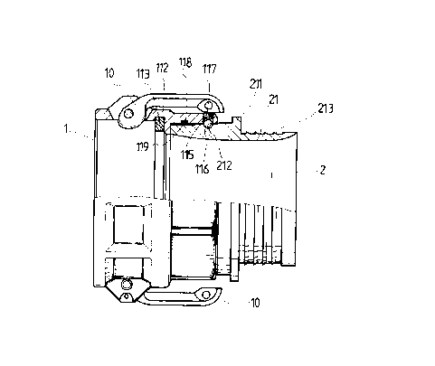
Figure 3 is a sectional assembly view of the pipe connector
shown in Figure 2.
Figure 4 is a cross sectional view of the present invention
showing the steel balls installed in the annular ball grooves
between the inside wall of the first connector member and the
outside wall of the second connector member.
Figure 5 is an applied view of the present invention,
showing the second connector member rotated in the first
connector member.
DETAILED DESCRIPTION OF THE PREFERRED EMBODIMENTS
Referring to Figure 2, a rotary pipe connector in
accordance with the present invention is comprised of a first
connector member 1, and a second connector member 2.
Referring to Figures from 3 through 5 and Figure 2 again,
the first connector member 1 comprises an axially extended center
through hole 11, an inside annular flange 111 raised around the
inside wall thereof within the center through hole 11, an annular
ball groove 114 provided around the inside wall within the center
through hole 11 in parallel to the inside annular flange 111, a radial
screw hole 15 extended from the annular ball groove 114 to the
periphery. a set of steel balls 116, which are inserted through the
radial screw hole 15 into the annular ball groove 114 after the first

CA 02242539 1998-08-20
connector member 1 and the second connector member 2 have been
connected together, a screw- rod 177 for threading into the screw
hole 15 to stop the steel balls 116 in the annular ball groove 114, a
plurality of inside annular grooves 118 provided around the inside
wall within the center through hole 11 in parallel to the annular
ball groove 114 and the inside annular flange 111, and a plurality
of O-rings 119 respectively mounted in the inside annular grooves
118. When the second connector member 2 is inserted into the
center through hole 11 of the first connector member 1, the O-rings
119 seal the gap. The second connector 2 is a cylindrical device
comprising a collar 211 raised around the outside wall 21 thereof,
an annular ball groove 212 provided around the outside wall 21 at
one side of the collar 211 corresponding to the annular ball groove
114 at the first connector member 1 for receiving the steel balls 116,
and a plurality of positioning flanges 213 raised around the outside
wall 21 at an opposite side of the collar 211 and sloping upwardly
forwards toward the collar 211 for securing a hose 3 to the second
connector member 2 (see Figure 5). Alternatively, the outside
wall 21 can have a plain surface for the mounting of a metal pipe by
welding.
Referring to Figures from 2 through 5 again, when the
second connector member 2 is inserted into the center through hole
4

CA 02242539 1998-08-20
11 of the first connector member 1 and stopped at the inside
annular flange 111. the annular ball grooves 114;212 are matched
together, and the gap between the inside wall of the first connector
member 1 and the outside wall of the second connector member 2
~ are sealed by the O-rings 119. After the installation of the second
connector member 2 in the first connector member 1, the steel balls
116 are inserted into the annular ball grooves 114,212, and then the
screw rod 117 is threaded into the radial screw hole 115 to stop the
steel balls 116 in the annular ball grooves 114,212. When
assembled, the second connector member 2 can be rotated in the
first connector member 1 through 360° (see Figure 5).
Referring to Figures 2, 3 and 5 again, two lock levers 10
are bilaterally pivoted to the first connector member 1 for quickly
securing the first connector member 1 to a fitting being inserted
into the first connector member, and a gasket ring 113 is mounted
inside the first connector member 1 and stopped at the inside
annular flange 111 at one side opposite to the second connector
member 2 to prevent a leakage after the installation of the fitting in
the first connector member 1.
While only one embodiment of the present invention has
been shown and descried, it will be understood that various
modifications and changes could be made thereunto without
5

CA 02242539 1998-08-20
departing from the spirit and scope of the invention disclosed.

Representative Drawing
A single figure which represents the drawing illustrating the invention.
Administrative Status

2024-08-01:As part of the Next Generation Patents (NGP) transition, the Canadian Patents Database (CPD) now contains a more detailed Event History, which replicates the Event Log of our new back-office solution.

Please note that "Inactive:" events refers to events no longer in use in our new back-office solution.

For a clearer understanding of the status of the application/patent presented on this page, the site Disclaimer , as well as the definitions for Patent , Event History , Maintenance Fee  and Payment History  should be consulted.

Event History

Description Date
Inactive: IPC from MCD 2006-03-12
Application Not Reinstated by Deadline 2001-08-20
Time Limit for Reversal Expired 2001-08-20
Deemed Abandoned - Failure to Respond to Maintenance Fee Notice 2000-08-21
Application Published (Open to Public Inspection) 2000-02-20
Inactive: Cover page published 2000-02-20
Classification Modified 1998-11-02
Inactive: First IPC assigned 1998-11-02
Inactive: IPC assigned 1998-11-02
Inactive: Filing certificate - No RFE (English) 1998-09-15
Filing Requirements Determined Compliant 1998-09-15
Application Received - Regular National 1998-09-14

Abandonment History

Abandonment Date Reason Reinstatement Date
2000-08-21

Fee History

Fee Type Anniversary Year Due Date Paid Date
Application fee - small 1998-08-20
Registration of a document 1998-08-20
Owners on Record

Note: Records showing the ownership history in alphabetical order.

Current Owners on Record
KURIYAMA OF AMERICA, INC.
Past Owners on Record
MARLIN MAAS
Past Owners that do not appear in the "Owners on Record" listing will appear in other documentation within the application.
Documents

To view selected files, please enter reCAPTCHA code :


To view images, click a link in the Document Description column. To download the documents, select one or more checkboxes in the first column and then click the "Download Selected in PDF format (Zip Archive)" or the "Download Selected as Single PDF" button.

List of published and non-published patent-specific documents on the CPD .

If you have any difficulty accessing content, you can call the Client Service Centre at 1-866-997-1936 or send them an e-mail at CIPO Client Service Centre.


Document
Description 
Date
(yyyy-mm-dd) 
Number of pages   Size of Image (KB) 
Abstract 1998-08-20 1 20
Description 1998-08-20 6 157
Claims 1998-08-20 2 54
Drawings 1998-08-20 5 113
Cover Page 2000-02-07 1 35
Representative drawing 2000-02-07 1 11
Courtesy - Certificate of registration (related document(s)) 1998-09-14 1 140
Filing Certificate (English) 1998-09-15 1 174
Reminder of maintenance fee due 2000-04-25 1 111
Courtesy - Abandonment Letter (Maintenance Fee) 2000-09-18 1 184