Sélection de la langue

Search

Sommaire du brevet 2242539 

Énoncé de désistement de responsabilité concernant l'information provenant de tiers

Une partie des informations de ce site Web a été fournie par des sources externes. Le gouvernement du Canada n'assume aucune responsabilité concernant la précision, l'actualité ou la fiabilité des informations fournies par les sources externes. Les utilisateurs qui désirent employer cette information devraient consulter directement la source des informations. Le contenu fourni par les sources externes n'est pas assujetti aux exigences sur les langues officielles, la protection des renseignements personnels et l'accessibilité.

Disponibilité de l'Abrégé et des Revendications

L'apparition de différences dans le texte et l'image des Revendications et de l'Abrégé dépend du moment auquel le document est publié. Les textes des Revendications et de l'Abrégé sont affichés :

  • lorsque la demande peut être examinée par le public;
  • lorsque le brevet est émis (délivrance).
(12) Demande de brevet: (11) CA 2242539
(54) Titre français: RACCORD ROTATIF DE CONDUITE
(54) Titre anglais: ROTARY PIPE CONNECTOR
Statut: Réputée abandonnée et au-delà du délai pour le rétablissement - en attente de la réponse à l’avis de communication rejetée
Données bibliographiques
(51) Classification internationale des brevets (CIB):
  • F16L 27/08 (2006.01)
  • F16L 37/20 (2006.01)
  • F16L 37/23 (2006.01)
(72) Inventeurs :
  • MAAS, MARLIN (Etats-Unis d'Amérique)
(73) Titulaires :
  • KURIYAMA OF AMERICA, INC.
(71) Demandeurs :
  • KURIYAMA OF AMERICA, INC. (Etats-Unis d'Amérique)
(74) Agent: ROBIC AGENCE PI S.E.C./ROBIC IP AGENCY LP
(74) Co-agent:
(45) Délivré:
(22) Date de dépôt: 1998-08-20
(41) Mise à la disponibilité du public: 2000-02-20
Licence disponible: S.O.
Cédé au domaine public: S.O.
(25) Langue des documents déposés: Anglais

Traité de coopération en matière de brevets (PCT): Non

(30) Données de priorité de la demande: S.O.

Abrégés

Abrégé anglais


A rotary pipe connector includes a first connector member
fastened to a liquid reservoir fitting, a second connector member
fastened to a liquid delivery means and inserted into the first
connector member, a plurality of steel balls inserted through a
radial screw hole at the first connector. member into matched
annular ball grooves between the inside wall of the first connector
member and the outside wall of the second connector member to
secure the first connector member and the second connector
member together, for permitting the second connector member to
be rotated with the liquid delivery means in the first connector
member, and a screw rod threaded into the radial screw hole to stop
the steel balls in the annular ball grooves.

Revendications

Note : Les revendications sont présentées dans la langue officielle dans laquelle elles ont été soumises.


What the invention claimed is:
1. A rotary pipe connector comprising
a first connector member fastened to a liquid reservoir
fitting. said first connector member comprising an inside wall
defining an axially extended center through hole, an inside annular
flange raised around the inside wall within said center through hole,
an annular ball groove provided around the inside wall within said
center through hole in parallel to said inside annular flange, a
radial screw hole extended from the annular ball groove of said
first connector member to the outside of said first connector
member;
a second connector member fastened to a liquid delivery
means and coupled to the center through hole of said first
connector member, said second connector member comprising a
collar raised around and outside wall thereof, an annular ball
groove provided around the outside wall and matched with the
annular ball groove at the inside wall of said first connector
member; and
a plurality of steel balls inserted through said radial screw
hole at said first connector member into the annular ball grooves of
said first connector member and said second connector member to
secure said first connector member and said second connector
7

member together, for permitting said second connector member to
be rotated with the liquid delivery means in said first connector
member.
2. The rotary pipe connector of claim 1 wherein said first
connector member comprises a plurality of inside annular grooves
provided around the inside wall thereof, and a plurality of O-rings
respectively mounted in the inside annular grooves within said first
connector member around the outside wall of said second
connector member.
3. The rotary pipe connector of claim 1 wherein said first
connector member further comprises a gasket ring mounted in an
inside annular groove thereof and stopped at one side of said inside
annular flange opposite to said first connector member.
4. The rotary pipe connector of claim 1 further comprising a
screw rod threaded into the screw hole at said first connector
member to stop said steel balls in said annular ball grooves
between said first connector member and said second connector
member.
8

Description

Note : Les descriptions sont présentées dans la langue officielle dans laquelle elles ont été soumises.

CA 02242539 1998-08-20
ROTARY PIPE CONNECTOR
BACKGROUND OF THE INVENTION
(a) Field of the Invention:
The present invention relates to a pipe connector, and more
particularly to a rotary pipe connector for securing a pipe to a
liquid reservoir fitting for permitting the pipe to be rotated through
360° relative to the liquid reservoir fitting.
(b) Description of the Prior Art:
Regular rubber hoses are intensively used in oil and
chemical delivery vehicles, pumpers, gasoline pumps, movable
water pumps, etc. for delivering oil, liquid chemicals, gasoline or
water. When connecting a rubber hose to a vehicle, pumper,
gasoline pump or water pump. a pipe connector shall be used.
When a pipe connector is fastened to a rubber hose and installed in
I~ a vehicle, pumper, gasoline pump or water pump, the rubber hose
cannot be freely rotated relative to the vehicle, pumper, gasoline
pump or water pump. If the rubber hose is twisted, the hose body
of the rubber hose is forced to deform, causing the liquid delivery
efficiency to be affected (see Figure 1). Further, frequently
twisting the rubber hose may cause the hose body to break. causing
a leakage. It is dangerous when a liquid chemical leaks out
through a crack in the rubber hose of a chemical delivery vehicle.

CA 02242539 1998-08-20
SUMMARY OF THE INVENTION
The present invention provides a rotary pipe connector for
securing a pipe to a liquid reservoir fitting for permitting the pipe
to be rotated through 360° relative to the liquid reservoir fitting.
A rotary pipe connector according to the preferred embodiment of
the present invention is comprised of a first connector member
fastened to the pipe. and a second connector member fastened to
the machine fitting and inserted into a center through hole at the
first connector member and stopped at an inside annular flange
inside the first connector member. A plurality of steel balls are
inserted through a radial screw hole at the first connector member
into matched annular ball grooves between the inside wall of the
first connector member and the outside wall of the second
connector member to secure the second connector member to the
inside of the first connector member, for permitting the second
connector member to be rotated with the connected pipe in the first
connector member.
BRIEF DESCRIPTION OF THE DRAWINGS .
Figure 1 is an applied view of a pipe connector according
to the prior art.
Figure 2 is an exploded view of a pipe connector according
to the present invention.
2

CA 02242539 1998-08-20
Figure 3 is a sectional assembly view of the pipe connector
shown in Figure 2.
Figure 4 is a cross sectional view of the present invention
showing the steel balls installed in the annular ball grooves
between the inside wall of the first connector member and the
outside wall of the second connector member.
Figure 5 is an applied view of the present invention,
showing the second connector member rotated in the first
connector member.
DETAILED DESCRIPTION OF THE PREFERRED EMBODIMENTS
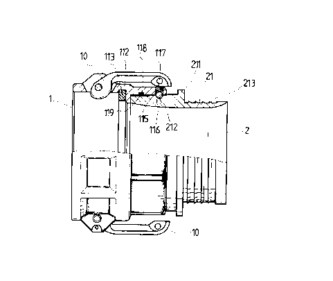
Referring to Figure 2, a rotary pipe connector in
accordance with the present invention is comprised of a first
connector member 1, and a second connector member 2.
Referring to Figures from 3 through 5 and Figure 2 again,
the first connector member 1 comprises an axially extended center
through hole 11, an inside annular flange 111 raised around the
inside wall thereof within the center through hole 11, an annular
ball groove 114 provided around the inside wall within the center
through hole 11 in parallel to the inside annular flange 111, a radial
screw hole 15 extended from the annular ball groove 114 to the
periphery. a set of steel balls 116, which are inserted through the
radial screw hole 15 into the annular ball groove 114 after the first

CA 02242539 1998-08-20
connector member 1 and the second connector member 2 have been
connected together, a screw- rod 177 for threading into the screw
hole 15 to stop the steel balls 116 in the annular ball groove 114, a
plurality of inside annular grooves 118 provided around the inside
wall within the center through hole 11 in parallel to the annular
ball groove 114 and the inside annular flange 111, and a plurality
of O-rings 119 respectively mounted in the inside annular grooves
118. When the second connector member 2 is inserted into the
center through hole 11 of the first connector member 1, the O-rings
119 seal the gap. The second connector 2 is a cylindrical device
comprising a collar 211 raised around the outside wall 21 thereof,
an annular ball groove 212 provided around the outside wall 21 at
one side of the collar 211 corresponding to the annular ball groove
114 at the first connector member 1 for receiving the steel balls 116,
and a plurality of positioning flanges 213 raised around the outside
wall 21 at an opposite side of the collar 211 and sloping upwardly
forwards toward the collar 211 for securing a hose 3 to the second
connector member 2 (see Figure 5). Alternatively, the outside
wall 21 can have a plain surface for the mounting of a metal pipe by
welding.
Referring to Figures from 2 through 5 again, when the
second connector member 2 is inserted into the center through hole
4

CA 02242539 1998-08-20
11 of the first connector member 1 and stopped at the inside
annular flange 111. the annular ball grooves 114;212 are matched
together, and the gap between the inside wall of the first connector
member 1 and the outside wall of the second connector member 2
~ are sealed by the O-rings 119. After the installation of the second
connector member 2 in the first connector member 1, the steel balls
116 are inserted into the annular ball grooves 114,212, and then the
screw rod 117 is threaded into the radial screw hole 115 to stop the
steel balls 116 in the annular ball grooves 114,212. When
assembled, the second connector member 2 can be rotated in the
first connector member 1 through 360° (see Figure 5).
Referring to Figures 2, 3 and 5 again, two lock levers 10
are bilaterally pivoted to the first connector member 1 for quickly
securing the first connector member 1 to a fitting being inserted
into the first connector member, and a gasket ring 113 is mounted
inside the first connector member 1 and stopped at the inside
annular flange 111 at one side opposite to the second connector
member 2 to prevent a leakage after the installation of the fitting in
the first connector member 1.
While only one embodiment of the present invention has
been shown and descried, it will be understood that various
modifications and changes could be made thereunto without
5

CA 02242539 1998-08-20
departing from the spirit and scope of the invention disclosed.

Dessin représentatif
Une figure unique qui représente un dessin illustrant l'invention.
États administratifs

2024-08-01 : Dans le cadre de la transition vers les Brevets de nouvelle génération (BNG), la base de données sur les brevets canadiens (BDBC) contient désormais un Historique d'événement plus détaillé, qui reproduit le Journal des événements de notre nouvelle solution interne.

Veuillez noter que les événements débutant par « Inactive : » se réfèrent à des événements qui ne sont plus utilisés dans notre nouvelle solution interne.

Pour une meilleure compréhension de l'état de la demande ou brevet qui figure sur cette page, la rubrique Mise en garde , et les descriptions de Brevet , Historique d'événement , Taxes périodiques et Historique des paiements devraient être consultées.

Historique d'événement

Description Date
Inactive : CIB de MCD 2006-03-12
Demande non rétablie avant l'échéance 2001-08-20
Le délai pour l'annulation est expiré 2001-08-20
Réputée abandonnée - omission de répondre à un avis sur les taxes pour le maintien en état 2000-08-21
Demande publiée (accessible au public) 2000-02-20
Inactive : Page couverture publiée 2000-02-20
Symbole de classement modifié 1998-11-02
Inactive : CIB en 1re position 1998-11-02
Inactive : CIB attribuée 1998-11-02
Inactive : Certificat de dépôt - Sans RE (Anglais) 1998-09-15
Exigences de dépôt - jugé conforme 1998-09-15
Demande reçue - nationale ordinaire 1998-09-14

Historique d'abandonnement

Date d'abandonnement Raison Date de rétablissement
2000-08-21

Historique des taxes

Type de taxes Anniversaire Échéance Date payée
Taxe pour le dépôt - petite 1998-08-20
Enregistrement d'un document 1998-08-20
Titulaires au dossier

Les titulaires actuels et antérieures au dossier sont affichés en ordre alphabétique.

Titulaires actuels au dossier
KURIYAMA OF AMERICA, INC.
Titulaires antérieures au dossier
MARLIN MAAS
Les propriétaires antérieurs qui ne figurent pas dans la liste des « Propriétaires au dossier » apparaîtront dans d'autres documents au dossier.
Documents

Pour visionner les fichiers sélectionnés, entrer le code reCAPTCHA :


Pour visualiser une image, cliquer sur un lien dans la colonne description du document. Pour télécharger l'image (les images), cliquer l'une ou plusieurs cases à cocher dans la première colonne et ensuite cliquer sur le bouton "Télécharger sélection en format PDF (archive Zip)" ou le bouton "Télécharger sélection (en un fichier PDF fusionné)".

Liste des documents de brevet publiés et non publiés sur la BDBC .

Si vous avez des difficultés à accéder au contenu, veuillez communiquer avec le Centre de services à la clientèle au 1-866-997-1936, ou envoyer un courriel au Centre de service à la clientèle de l'OPIC.


Description du
Document 
Date
(aaaa-mm-jj) 
Nombre de pages   Taille de l'image (Ko) 
Abrégé 1998-08-20 1 20
Description 1998-08-20 6 157
Revendications 1998-08-20 2 54
Dessins 1998-08-20 5 113
Page couverture 2000-02-07 1 35
Dessin représentatif 2000-02-07 1 11
Courtoisie - Certificat d'enregistrement (document(s) connexe(s)) 1998-09-14 1 140
Certificat de dépôt (anglais) 1998-09-15 1 174
Rappel de taxe de maintien due 2000-04-25 1 111
Courtoisie - Lettre d'abandon (taxe de maintien en état) 2000-09-18 1 184