Note: Descriptions are shown in the official language in which they were submitted.
CA 02242~6 1998-08-24
DEVICE FOR THE DIRECTIONAL TRANSMISSION AND THE DIRECTIONAL
RECEPTION OF MODULATED LIGHT WAVES
FIELD OF THE INVENTION
The present invention relates to a device for the directional transmission and the
25 directional reception of modulated light waves between geostationary satellites, or
respectively geostationary satellites still close to earth by means of a telescope.
BACKGROUND OF THE INVENTION
Fiber-optical communications systems have revolutionized the wire-dependent datatransmission over large distances within a few years. In connection with directional
radio installations, which had been dominant up to that time, systems already in service
today can be considered to be superior in every respect in view of the availablebandwidth. Only mobile communications are able to profit indirectly from this advance
by means of efficient fixed networks, since cellular networks also need to utilize narrow-
band and trouble-prone radio on a portion of the transmission path. In connection with
the transmission via or between satellites, large distances still need to be overcome,
CA 02242~6 1998-08-24
which absolutely requires large transmission outputs and antennas, which in turn runs
counter to the desire for systems as compact and as light as possible for space travel.
For this reason efforts were undertaken fairly soon after the triumphal march of the
fiber-optical communication technology to also use its advantages for optical
5 communications in free space by means of suitable systems.
New factors in the fiber-optical communications technology, inherent in the
system, have shown themselves to be limiting, in particular in connection with bridging
great distances, especially the dispersion in the dielectric wave guide used for10 transmission, and various non-linear effects of its material. Optical communication in
free space again meant the return of old limiting effects of radio technology and wire-
dependent communications. Here, the loss of signal output on the transmission path
and the effects of foreign signals dominated again. However, in fiber- optical
communications the extreme limits of the energy of a symbol used for transmission
are not expressed by the terms describing the phenomenon of thermal noise, but by
means of photons per bit.
For example, at an error quotient of 1/1,000,000,000, 10.5 photons per bit are
inherently required for the assured transmission of data by means of intensity
20 modulation (J.S. Senior, "Optical Fiber Communications, Principles and Practice",
second edition, Prentice Hall, pp. 469 to 471).
Better results can be achieved with pulse-position modulation, as well as various
coherent techniques, in particular methods with homodyne transmission. The best
2s realized results were obtained by means of homodyne superimposition (less than 30
photons per bit). Since there is a clear requirement for low energy consumption for
space-based systems, an optical system for data transmission between distant
geostationary satellites should transmit and receive light waves by the largest possible
and very accurately aligned aperture. This, in turn, can only be realized, starting at a
30 defined size and while maintaining a low weight, in the form of a reflecting telescope.
Reflecting telescopes in the so-called coaxial form are known in numerous designs,
the systems in accordance with Gre~3ory, Cassegrain and Schmidt should be
mentioned (Eugene Hecht, "Optics", second edition, Addison-Wesley Publishing
Company, Reading, MA, USA, pp. 197, 198).
CA 02242~6 1998-08-24
-.3.-
Common to all of them is the system-related disadvantage of the partial central
covering of the aperture by the collecting mirrors and their suspension devices. In this
case a compromise between mechanical sturdiness and losses because of covering of
5 the aperture must be found.
Generally, an additional screen is required, which prevents the reflection of
scattered light, which is encouraged by the collecting mirror and its suspension, in the
direction of the light to be received. The simultaneous use of such a telescope for
radiating a light wave as well as for receiving an oppositely entering light wave
generally results in significant disadvantages, since the said collecting mirror and its
suspension reflects a portion of the high output transmitted light in the direction of the
simultaneously entering light wave and results in interferences because of
superimposition. Accepting great losses regarding the imaging quality, this problem
can be bypassed by the use of an oblique reflecting telescope proposed by Kutter.
However, the mentioned imaging errors result in the waste of valuable transmission
output.
OBJECT AND SUMMARY OF THE INVENTION
It is therefore the object of the invention, which will be described in what fol!ows,
to overcome the mentioned disadvantages of the prior art by employing an obliquereflecting telescope, which is free of imaging errors but permits a simultaneousbidirectional use for transmitting and receiving a light wave.
This object is attained in accordance with the invention by means of the
characterizing portion of claim 1. Advantageous further developments and
improvements ensue from the dependent claims.
The said oblique reflecting telescope is constructed from a plurality of mirrors with
refractive power and has a surface which provides images in a refraction-limitedmanner which, in contrast to the system developed by Kutter, have a common optical
axis. The characteristic feature of the optical systems lies in that the surfaces of the
individual mirrors can be imagined as partial surfaces cut out of the axis-symmetrical
CA 02242~6 l998-08-24
-.4.-
mirrors arranged on a common optical axis. Cutting out partial surfaces creates the
actual structure of an oblique reflecting telescope, but is also necessary for preventing
mutual obscuration and because of the impossibility of the intersection of mirror
surfaces.
A further characteristic of the invention lies in the structure of the housing
containing the mirrors of the telescope. To the extent necessary for maintaining the
imaging quality, the relative position of the mirrors in respect to each other is
stabilized by a separate support frame made of Invar or a comparable material. This
means can be omitted when using a mechanically and thermally sufficient stable
10 housing.
In accordance with the invention, the housing for the oblique reflecting telescope
is made of a particularly light and thermally stable structure. This consists of a
honeycomb structure known from aircraft manufacturing, which is closed off at both
15 sides by a material with poor thermal expansion properties. In addition to the proven
Invar, the considerably lighter glass-ceramic material Zerodur~ has been used for the
first time in the present invention for these layers which, compared with Invar, in
addition shows considerably less thermal expansion. Furthermore, a plastic material
was used for the first time for the same purpose. It is a very temperature-resistant
20 thermoplastic material (Peak), which is mixed with a large proportion of stabilizing
fiberglass sections, which see to sufficient mechanical and thermal stability.
In addition, the housing for the telescope is designed in such a way that a screen,
which is not as urgently necessary because of the lack of a collecting mirror, has
25 already been integrated over a relatively short length.
An essential advantage of the invention lies in the low weight of the telescope,which is seated so it is rotatable around one or several axes, in particular when it is
possible to omit a supporting frame inside of the housing because of the
30 advantageous static properties of the housing, which has been assembled for reasons
of weight saving from the plates manufactured in the sandwich structure with thealuminum honeycomb mentioned, which is possible in particular if, in accordance with
a further characteristic of the invention, the mass of the mirror body used has been
reduced to a minimum, determined by the strength requirements, by recesses made
CA 02242~6 1998-08-24
by means of bores on its side facing away from the light.
Because of the employment of an oblique reflecting telescope, which provides
error-free images, a further advantage lies in that it is possible, corresponding to
telescopes which mainly operate with lenses, to use more than two mirrors with
refractive power, by means of which it is possible to transfer the advantages, which
can be achieved with refractive
systems completely equipped with lenses, to optical systems equipped with mirrors.
Further details, characteristics and advantages of the invention result not onlyfrom the claims and characteristics which can be taken from them, either individually
or in combination, but also from the following description of preferred exemplary
embodiments.
BRIEF DESCRIPTION OF THE DRAWINGS
Fig. 1 represents two schematic sketches of different embodiments of oblique
reflecting telescopes,
Fig. 2 shows the special optical construction of the oblique reflecting telescope
used,
Fig. 3 represents a cross section as well as a sagittal section through a
lightweight support housing containing the oblique reflecting telescope,
Fig. 4 represents a cross section as well as a sagittal section through a
lightweight support housing containing the oblique reflecting telescope, including a
stabilizing support frame,
Fig. 5 represents two embodiments of obtuse-angled connections between the
segments of the lightweight housing used,
Fig. 6 represents an embodiment of a right-angled connection between the
CA 02242~6 l998-08-24
-.6.-
segments of the lightweight housing used,
Fig. 7 represents an embodiment of an acute-angled connection between the
segments of the lightweight housing used,
Fig. 8 represents an exterior view of an optical front end of an optical
communication system containing an oblique reflecting telescope,
Fig. 9 is an exploded view of the optical front end.
DETAILED DESCRIPTION OF THE PREFERRED EMBODIMENTS
Fig. 1 shows the form of an oblique reflecting telescope 2 developed by Kutter,
which consists of mirrors 8 and 10 with refractive power, which are laterally offset from
each other in respect to the incident light beam 6, and of a flat deflecting mirror 12.
The mirrors 8 and 10 generally have optical axes which are not parallel with theincident light beam 6. This necessarily results in imaging errors with an increased
deviation from the optical axis. This defect is removed by means of an improved
20 construction 4, in that all mirrors with refractive power 14, 16 and 18 have a common
optical axis 26, which is parallel in respect to the incident light beam 6 as well as to
each other. Thus the said mirrors are sections of dynamically balanced mirror
surfaces which cover and intersect each other and have a common axis of symmetry,
which can be seen even more clearly by means of their extension 28, 30 and 32
25 shown in sagittal section in Fig. 2.
A planar mirror 20 sends the light beam 6 into a refractive optical device 22,
which in general is followed by an optical bench containing appropriate quantum-optical devices. For the purpose of screening out light being scattered in laterally, the
30 mirrors 14, 16, 18 and 20 have been placed into a housing in accordance with Fig. 3,
which is put together of plates 34 of different thickness.
As represented in Fig. 5, in an embodiment known from aircraft manufacturing,
the plates 34 are made of a hexagonal honeycomb-like structure 36, which is located
CA 02242~6 1998-08-24
between two thin layers 38 and is connected with them by gluing or other techniques.
While the honeycomb-like structure 35 can be made of aluminum, materials showinglittle thermal expansion are provided for the thin layers 38. Besides proven materials,
for example Invar, these can also be other suitable materials, such as Zerodur~
5 which, besides even less thermal expansion, also results in considerable weight
savings.
Besides the glass-ceramic material Zerodur(~, plastic materials can also be used.
Thermoplastic materials make simpler processing possible and, with an appropriately
10 high processing temperature, can also be employed at even higher temperatures.
Materials modified by the admixture of fiberglass sections meet both mechanical and
thermal requirements for use in space. Therefore thermal expansion is extremely low,
temperature resistance and mechanical stability are sufficient. The property of little
thermal expansion
can be particularly optimized in that a large proportion of fiberglass sections or fiber
sections of other materials is admixed to the plastic material, wherein the glass or
other material used for the fiber sections has the lowest thermal expansion.
In addition, fiberglass or fibers made of other materials can be present within a
thin layer 38 in the form of a matrix structure. In order to keep the mass of the mirrors
14, 16, 18 and 20 as well as further mirrors as low a possible, they can be provided on
their side facing away from the light with a plurality of bores, not necessarily required
for fastening them on the housing, which in a regular embodiment approximately result
25 in recesses of also hexagonal honeycomb-like structure. Since keeping the relative
position of the mirrors 14 and 16 in respect to each other is very critical for the quality
of the optical image, maintaining them exactly can be additionally assured in
accordance with Fig. 4 by supporting plates 40 and struts 42 made of a material of low
heat expansion. Obtuse-angled connections between plates 34 are represented in
30 Fig. 5.
On the one hand, the connection between two plates can take place in a final
manner by an adhesive connection 44 at respective appropriately beveled plate
edges, which is provided with additional stability by glued-on support material 46. On
CA 02242~6 l998-08-24
the other hand, a connection can also be provided by means of an adhesive contact
44 between a rail 48, which is provided with threaded holes at defined distances, and
the plate 34, wherein a corresponding rail 50, which is provided with holes and glued
together with the second plate 34 to be connected, is fastened on the rail 48 by means
5 of threaded screws 52.
Figs. 6 and 7 represent a corresponding right-angled, or respectively acute-
angled connection. The integration of an oblique reflecting telescope of the type
described by means of Fig. 3 and Fig. 4 within a front end of an optical free space
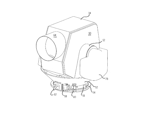
10 optical communications system is represented in Figs. 8 and 9. The housing 50 put
together from plates 34 is seated in a yoke 52, which is rotatably seated in a ring 54.
An angle encoder 56 for determining the actually set angle of rotation around anazimuth axis 69, a motor 58 acting on the ring 54 via a gear 60, as well as a lock 62,
intended for the rest phases and blocking all rotary movements, are fixed on the ring
15 54. The lock 62 is used for securing the entire device when used in a satellite, which
is subjeted to extreme acceleration during the start of the rocket. In addition, a screen
64, which acts in addition to the housing 50, has been attached to the housing 50.
The telescope can be turned around the elevation axis by means of hollow pins 66attached to the housing 50, while simultaneously light is coupled in, or respectively
20 conducted out of the telescope through the interior of one of the two hollow pins 66 by
means of a flat deflecting mirror 74. The devices necessary for this are combined in
an optical bench 76, which is fastened on the yoke 52 next to this hollow pin 66. This
screening cover 78 takes up heat generated by the optical bench 76 and radiates it
into free space. A further cover 82, which screens and cools components 80 of the
25 electronic device close to the system, serves the same purpose. Furthermore, a drive
72 acting on the second hollow pin 66 for setting the elevation angle of the telescope
rotated around an elevation axis 67, as well as a measuring sensor 70 for its
detection, are oppositely located in the other arm of the yoke 52 and attached to the
yoke. The measuring sensor 70 consists of two rings which can be moved in respect
30 to each other and are in fixed contact with respectively the hollow pin 66 or the yoke
52, wherein the opening of the yoke 66 is in no case completely covered so as tomake possible the entry, or respectively exit of light via the deflecting mirror 74. The
measuring sensor 70 and the drive 72 are used as sensor, or respectively actuator for
a control circuit arranged in the component 80 in the vicinity of the system. Further
CA 02242~6 l998-08-24
.9.
modules arranged in the component 80 close to the system control the temperature of
a quantum-optical amplifier as well as the fine alignment and the amount of lead for
the light beam to be transmitted.
The optical bench 76 is fastened to the yoke 52 and is rotated azimuthally alongwith it, while a change in the transmitting, or respectively receiving direction in
elevation takes place by rotating the deflecting mirror 74 along with the telescope
being rotated in elevation which, in view of the use of circularly polarized light for the
transmission, does not require the adaptation of a linear polarization direction. This
represents an advantageous compromise for the special case of employment of the
connection between two satellites located in geostationary orbit, since by means of the
change of the elevation angle of the telescope located in the housing 50 it is possible
to reach a large number of neighboring satellites, wherein only slight adaptations of
the azimuth angle set by means of the motor 58 via the gear 60, as well as the angle
15 encoder 56 are required. If therefore the actuation range of the latter is limited as a
whole to less than 10 degrees, no special cable connection, which is capable of being
rotated, of the electronic device required for operation is required from the body of a
satellite to the optical bench 76, or to components 80 in the vicinity of the system.