Note: Descriptions are shown in the official language in which they were submitted.
CA 02242798 1998-07-09
J J P-1 59
MODULAR INSTRUMENTATION FOR BONE PREPARATION
AND IMPLANT TRIAL REDUCTION OF ORTHOPEDIC IMPLANTS
CROSS REFERENCE TO RELATED APPLICATIONS
Not applicable.
STATEMENT REGARDING FEDERALLY SPONSORED RESEARCH
Not applicable.
BACKGROUND OF THE INVENTION
The invention relates to instruments used in bone preparation and implant
trial
reduction during joint arthroplasty procedures. More particularly, the
invention relates to
modular instruments used to prepare the tibia to accept a prosthetic tibial
tray, and to
instruments useful as trial tibial trays.
Joint arthroplasty procedures in which a diseased and/or damaged natural joint
is
replaced with a joint prosthesis are well known. Among the more common joint
arthroplasty
procedures are those that involve replacement of knee joints and hip joints.
Knee arthroplasty is a surgical procedure by which a diseased and/or damaged
natural
knee joint is replaced with a prosthetic knee joint. A typical total knee
prosthesis includes a
femoral component, a patella component, a tibial tray or plateau, and a tibial
bearing insert.
The femoral component generally includes a pair of laterally spaced apart
condylar portions,
the distal surfaces of which articulate with complementary condylar elements
formed in a
tibial bearing insert.
-1-
CA 02242798 1998-07-09
within a prepared cavity of the tibia that is formed during the surgical
procedure. The tibial
tray is secured to the tibia by bone cement and/or by press fit fixation
techniques. The tibial
bearing insert is typically affixed to the superior surface of the tibial
tray.
During the course of a joint arthroplasty procedure, surgeons must evaluate
the size
and condition of the patient's bones (e.g., the tibia) that will accept a
component of the joint
prosthesis. In addition, the affected bones must be prepared to receive the
prosthesis
components. Bone preparation and the choice of the appropriate prosthesis
components are
factors which significantly influence the success of a joint arthroplasty
procedure.
Obviously, the bone preparation procedures are tedious and time consuming.
Once a bone has been properly prepared to accept a prosthesis component,
surgeons
typically utilize a "trial" system of prosthesis components that are provided
by the prosthesis
manufacturer. The trial components are sample prosthesis components, available
in various
sizes and shapes, that are intended to be placed into the prepared bone on a
temporary basis
for evaluation purposes only. Typically, surgeons evaluate a number of
different trial
components to determine the size and/or shape of a prosthesis component that
will best suit a
patient's needs.
In many joint arthroplasty procedures separate sets of tools and components
are used
to prepare the bone and subsequently to evaluate various prosthesis trial
components. The
use of separate sets of tools and components for these steps in a joint
arthroplasty procedure
further complicates an already difficult and time consuming process. Many
prior art
techniques require the removal of all bone preparation components after the
bone has been
prepared. Subsequently, the trial components are then sampled within the
prepared bone.
U.S. Patent No. 5,628,749 discloses instrumentation useful to prepare the
proximal
tibia to accept a tibial prosthesis. This instrumentation enables a surgeon to
effect all
necessary resection and drilling of the femur. When this is accomplished, a
tibial trial is
-2-
CA 02242798 1998-07-09
placed on the prepared tibia for evaluation of size and fit. Other instruments
useful for
preparation of the proximal tibia are disclosed in U.S. Patent No. 4,759,350.
U.S. Patent No. 5,609,642 discloses a tibial trial and bone preparation
system. This
system enables a surgeon to place a tibial tray trial on a resected tibia, and
to rotate the tray
trial to a preferred position. When the preferred position is achieved femoral
and tibial trials
are allowed to articulate with each other through the full range of motion of
the knee. The
trial tibial bearing insert is then removed from the trial tibial tray and the
tibia is further
prepared using a fm punch.
SUMMARY OF THE INVENTION
The invention is directed to a modular system that is used during the bone
preparation
and trial reduction phases of joint arthroplasty surgery. In particular, the
system is
particularly applicable to modular instruments for preparation of the proximal
tibia, and to
trial components for the tibial tray and the tibial bearing insert.
The system of the invention includes a trial tibial tray template element that
serves
both as a template, or guide, during preparation of the tibia and as a tibial
tray trial element
during the fitting of a tibial bearing insert. The tibial tray trial element
has a superior
surface and a bone contacting inferior surface. At least one guide aperture
extends through
the element from the superior to the inferior surfaces thereof. Further, the
trial tibial tray
template element preferably includes at least one locking aperture, and
preferably at least two
locking apertures, that are positioned on the opposite sides of the guide
aperture and which
extend through the superior and inferior surfaces of the element. One or more
slots may
extend radially from the central aperture.
The system also includes at least one punch bushing that is selectively
mateable with
the trial tibial template element. The punch bushing serves both as the guide
or template
-3-
CA 02242798 1998-07-09
during the bone preparation procedures, and also as a trial element that
remains mounted
within the patient's tibia during the trial portion of the surgical procedure.
The punch
bushing is an elongate member that has proximal and distal ends. A proximal
end of the
punch bushing includes a collar that is sized and configured to mate, in a
clearance fit, with
the guide aperture of the trial tibial tray template element. The punch
bushing extends
distally from the collar such that the diameter of the bushing generally
tapers from proximal
to distal ends thereof. The distal end is adapted and configured to mate with
a prepared
cavity within the patient's tibia and, accordingly, it assumes the size and
shape of the distal
portion of a permanent tibial tray prosthesis. The punch bushing further
includes a central
bore that extends at least partially into the bushing from the proximal
surface of the collar.
Further, at least two opposed slots extend radially from the central bore at
least partially into
the bushing.
The system also includes at least one tibial punch that is insertable within
the bore
and the slots of the punch bushing to create a further opening within the
patient's tibia of a
size and shape that is complimentary to the tibial punch. The tibial punch has
a central hub
with proximal and distal ends. Wedge-like fins extend radially from the
central hub and are
tapered in width from proximal to distal ends thereof. The outer edges of the
wedge-like
element preferably are bone penetrating. The punch is of a size and shape such
that it is able
to fit within the bore and slots of the punch bushing. A proximal end of the
tibial punch
includes a connecting surface that has a top, impact surface that can be used
to hammer the
tibial punch into the tibia.
The system also includes a selection of trial tibial bearing inserts, each of
which has a
superior articulation surface and an inferior surface that includes a mating
aperture. The
mating aperture is configured to selectively mate with the connecting surface
of the tibial
punch.
The system of the invention is useful in the following manner. The trial
tibial tray
template element is secured to a proximal portion of a patient's tibia, which
previously may
CA 02242798 1998-07-09
have been prepared by a resection procedure. A drill bushing can then be
joined to the
superior surface of the element and, using a suitable bone drill operated
through the drill
bushing, a cavity of desired dimensions is formed within the patient's tibia.
The drill and
drill bushing are removed and the punch bushing is inserted into the cavity
while allowing
the collar of the punch bushing to mate with the guide aperture of the trial
tibial tray
template element. Next, the tibial punch is inserted within the punch bushing,
in the proper
orientation, and it is forced, for example by use of a mallet, through the
punch bushing and
into the tibia to alter the shape of the cavity such that it is complementary
to that of the tibial
punch. The tibial punch remains in place, together with the trial tibial tray
template element
and the punch bushing. The surgeon can then attach one or more trial tibial
bearing inserts
to the connecting surface of the tibial punch to evaluate the size, shape and
orientation of a
tibial bearing insert needed for a given patient.
BRIEF DESCRIPTION OF THE DRAWINGS
Figure 1 is an exploded, perspective view of components of the system of the
invention.
Figure 2 is an isometric view of the system of the invention, assembled and
mounted
upon a tibia that is shown in phantom.
Figure 3 illustrates an exploded perspective view of the trial tibial tray
template
element of the system together with a drill bushing and a bone drill bit.
Figure 4 is an isometric view of a portion of the system of the invention
illustrating
the trial tibial tray template element mounted to a tibia, shown in phantom,
with the drill
bushing mounted to the element and a bone drill adjacent to the drill bushing.
Figure 5 is an anterior view of the tibial punch.
-5-
CA 02242798 1998-07-09
Figure 6 is a side sectional view of the tibial punch shown in Figure 5, at
lines 6-6.
Figure 7 is a detailed view of a portion of the wedge-like element of the
tibial punch
shown in Figure 5.
Figure 8 is a top view of the trial tibial tray template element of the
system.
Figure 9 is a perspective view of a punch bushing of the system.
Figure 10 is a side view of the punch bushing Figure 9.
Figure 11 is a sectional view at lines 11-11 of the punch bushing shown in
Figure 10.
Figure 12 is a top view of the punch bushing of Figure 9.
Figure 13 is a bottom view of a representative trial tibial bearing insert of
the system
of the invention.
DETAILED DESCRIPTION OF THE INVENTION
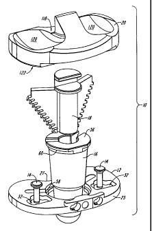
As shown in Figures 1 and 3 the modular bone preparation and trial system of
the
invention comprises various components that are useful to prepare the bone to
receive a joint
prothesis and also to evaluate the fit of various prosthesis components. These
components
include a trial tibial tray template element 12, punch bushing 16, tibial
punch 18 and trial
tibial bearing insert member Z0. The system may optionally include a drill
bushing 22 and a
drill member 24, as shown in Figure 3.
Referring to Figures 1 through 4 and 8, the trial tibial tray template element
12 has a
superior surface 26 and an inferior surface 28, and anterior and posterior
sides 25, 27. A
guide aperture 30 is substantially centrally disposed on the element 12 and
extends through
CA 02242798 1998-07-09
the superior and inferior surfaces 26, 28 thereof. The trial tibial tray
template element 12
preferably includes locking apertures 32 which may be disposed on opposite
sides of the
central aperture 30. In addition, at least two slots 34 extend radially, and
preferably
posteriorly, from the guide aperture 30. Slots 34 extend through the superior
and inferior
surfaces 26, 28 of element 12. Optionally, the trial tibial tray template
element 12 includes
an anterior flange 36 that is slightly raised above the superior surface 26 of
the element 12.
Anterior flange 36 includes one or more apertures 38. Flange 36 and apertures
38 provide a
mechanism to cooperate with a handle (not shown) used to manipulate and move
the element
12.
The guide aperture 30 may be substantially circular. In a preferred
embodiment,
however, the guide aperture 30 is substantially D-shaped and includes a
perimeter having an
arc portion 40 and a flat, non-arc portion 42. The D-shaped perimeter of the
guide aperture
is intended to help properly position and lock other components within the
guide aperture 30,
and it is understood that other profiles, besides D-shaped, may be employed.
Further, in a
preferred embodiment the non-arc portion 42 of the perimeter is adjacent an
anterior side 25
of the trial element 12, but it is understood that this non-arc segment may be
located at other
portions of the perimeter.
The nominal diameter (D~1) of the guide aperture 30, measured in the medial-
lateral
plane, is in the range of about 1.0 to 1.30 inches. Likewise, the nominal
diameter (D~p) of
the guide aperture 30, measured in the anterior-posterior plane, is in the
range of about 0.80
to 1.20 inches. One of the ordinary skill in the act will appreciate that the
diameter of the
guide aperture 30 may be lesser or greater than the values noted above.
As noted above, slots 34 extend radially from a portion of the guide aperture
30.
Although preferred, it is not necessary that the trial tibial tray template
element 12 include
slots 34. However, when present, the slots should be of a length of
approximately 1.00 to
1.50 inches and a width of about 0.15 to 0.38 inch. The slots 34 should extend
completely
through the template element 12 from the superior surface 26 to the inferior
surface 28. The
CA 02242798 2006-03-10
slots 34 may extend at any desired angular orientation from the guide aperture
3 0 . In a
preferred embodiment, however, the slots 34 are posteriorly directed and
extend at an angle
relative the transverse axis 46 of between 0 and 75 degrees in the posterior
direction. In one
embodiment, the slots 34 extend at an angle of between about 30 and 60
degrees, and most
preferably at an angle of about 45 degrees. In another embodiment the angle
formed by the
slots 34 with the transverse axis 46 is 0 degrees. It is further understood
that each of the
slots 34 may extend at a different angle relative to transverse axis 46.
The trial tibial tray template element 12 preferably includes one or more
locking
apertures 32 that are used to affix the elements 12 to the tibia when the
element 12 is
properly positioned. A locking mechanism, such as bone penetrating pins 14,
cooperates
with the locking aperhwes 32 to affix the element 12 to the tibia. In a
preferred embodiment
the pins 14 are elongate bone pins that are driven into the tibia to secure
the elements 12 in
position. Locking pins 14 preferably have a length in the range of about 10 to
25 mm and
include a bone penetrating distal end 48.
Figures 1, 2, 4 and 9-12 illustrate the punch bushing 16, which is an elongate
member having proximal and distal ends 50, 52. The proximal end 50 preferably
includes a
collar 54 that is of a size and shape complementary to guide aperture 30.
Preferably, the
collar 54 is sized to fit within guide aperture in a clearance fit such that a
superior surface 56
of the collar 54 mounts in a manner such that it is slightly recessed or flush
with respect to
superior surface 26 of trial element 12. In a preferred embodiment the guide
aperture 30
includes a shoulder 58 that supports an inferior surface 60 of the collar S6
to ensure that the
superior surface of the collar 54 is slightly recessed with respect to
superior surface 26 of
element 12.
In a preferred embodiment the collar 54 is substantially D-shaped having a
perimeter
with an arc portion 62 and a flat non-arc portion 64.
_g_
CA 02242798 1998-07-09
The proximal end 50 and collar 54 of punch bushing 16 preferably include a
central
bore 68 that may be substantially circular in shape. The bare 68 extends at
least partially
into bushing 16. The bore 68 may have a diameter that is substantially
constant along its
entire length, or the diameter may vary with the depth of the bore. In one
embodiment,
illustrated in Figure 11, the bore has a substantially constant first diameter
region 69 that
extends over a majority of its length. Region 69 terminates in a restricted
diameter region
70 that extends to the distal end 72 of the bore.
Slots 35 preferably extend radially from bore 68. The slots 35 are intended to
cooperate with slots 34 of trial element 12 to form a guide for the 'wedge-
like fins 63 of tibial
punch 18. As such, the size and orientation of slots 35 should be as described
above for
slots 34.
Preferably, slots 35 extend radially and posteriorly from the bore 68. The
angle
formed by each slot with the transverse axis 46 of the punch bushing 16 is in
the range of
about 0° to 75° in the posterior direction. Preferably, the
slots 35 extend at an angle from
about 30° to 60°, and most preferably at an angle of about
45°. The slots 35 should have a
length of about 5 to 50 mm and a width of about 2 to 8 mm. Preferably the
slots 35 extend
within the bore 68 to a depth of about 25 mm.
The depth and diameter of the bore 68 may vary depending upon the requirements
of
a given application. Generally, the bore should be sized and shaped so as to
accept the tibial
punch, as described below. In an exemplary embodiment, however, the diameter
of the bore
is in the range of about 0.40 to 1.20 inches. In a preferred embodiment,
illustrated in Figure
11, the diameter in region 69 is from about 0.80 to 1.00 inch. The length of
the region 69 is
about 1.2 to 2.0 inches. Further, the diameter of region 70 tapers at an angle
of about 30°
to 50° from about 0.70 to 0.50 inch. The length of region 70 is about
0.30 to 0.70 inch.
With further reference to Figures 9 through 11, the punch bushing 16 includes
an
outer surface 74. The outer surface 74 is intended to be implanted within the
tibia to form a
-9-
CA 02242798 1998-07-09
bone-contacting surface. The distal end 52 of punch bushing 16 preferably is
spherical. The
size and shape of the outer surface of punch bushing may vary depending upon
the
requirements of a given application. Generally, however, it is understood that
the distal end
52 is intended to serve the purpose of a tibial stem prosthesis. Accordingly,
it should be of a
size and shape consistent with that desired for the distal portion of a
permanent tibial tray
prosthesis.
In one embodiment, the outer surface has a first region 76 that is disposed
distally of
the collar. A second region 78 is formed distally of the first region.
Preferably, the first
region 76 has a diameter that tapers from a widest portion, at a proximal end
of first region,
to a narrowest portion at the distal-most end of the first region. Preferably,
the diameter of
the widest portion of the first region 76 is approximately 0.90 to 1.00 inch.
The taper of the
first region 76 preferably extends at an angle of about 5 degrees to 6
degrees, and most
preferably about 5.75 degrees. Similarly, the diameter at the widest, most
proximal portion
of the second region 78 is in the range of about 0.60 to 0.70 inch, and most
preferably is
about 0.68 to 0.69 inch. In one embodiment the length of the first region 76
is
approximately 1.0 to 1.2 inch while the length of the second region 78 is
about 2.00 to 2.10
inch.
The tibial punch 18 is a substantially wedged-shaped member that is inserted
through
the punch bushing 16 and into a patient's tibia 21 to form an opening in the
bone that will be
of a suitable size and shape to receive the fin elements of a prosthetic
tibial tray (not shown).
The tibial punch includes a hub 80 that is substantially elongate and
cylindrical. Two wedge-
like fins 63, which extend from opposite sides of the central hub 80, have a
width that tapers
from proximal to distal ends 82, 84 thereof. In addition, the outer edges 86
of the wedge-
like fins are of a shape and/or configuration to facilitate bone penetration.
In one
embodiment the outer edges are serrated.
A proximal end 88 of the tibial punch 18 includes a connecting element 90 that
will
protrude above the superior surface of trial element 12 when the system is
fully assembled.
-10-
CA 02242798 2006-03-10
The connecting element 90 preferably includes a base surface 92 that is
normally horizontally
oriented. The base surface 92 is separated from a top surface 94 by a vertical
connecting
surface 96. The top surface 94 is preferably horizontal. The connecting
element 90 is
configured to mate with a universal handle (not shown) which can receive blows
from a
mallet (not shown) while the punch 18 is being forced into a patient's tibia.
The space 9 $
between the base surface 92 and the top surface 94 forms a lip 100 that can be
used to
engage or mate with a trial tibial bearing insert 20, as described below.
The size and shape of the tibial punch 18 should be such that it is able to
fit within
the bore 68 and slots 35 of the punch bushing 16 in a clearance fit. That is,
the cylindrical
hub 80 should be of substantially the same shape and a slightly smaller
diameter than the
bore 68 of the punch bushing 16. Similarly, the wedge-like fins 63 should
extend from the
hub 80 at substantially the same angle as do the slots extend from the bore of
the punch
bushing 16. Thus, the wedge-like fins 63 extend from the hub 80 at an angle,
relative to the
transverse axis 46, of between 0 and 75 degrees. In one embodiment the angle
formed by
fins 63 with the transverse axis 46 is from about 30 to 60 degrees, and most
preferably,
about 45 degrees. In another embodiment the angle formed by fins 63 with
transverse axis
46 is 0 degrees. It is further understood that each of the fins 63 may extend
at a different
angle relative to transverse axis 46.
As noted above, the width of fins 63 tapers from the proximal to the distal
ends 82,
84 of the tibial punch. The taper angle « can vary, but it preferably is in
the range of about
50° to 65°. The width of the punch, at its widest point
(measured from opposite edges of
fins 63) is about 1.85 inches. The width tapers to about 0.65 inch at the
narrowest portion
of the tibial punch.
As noted above, the outer edges 86 of the wedge-like fins 63 may be serrated.
Figures 5 through 7 illustrate one embodiment in which the outer edges 86 form
bone
penetrating teeth 102. As illustrated, each tooth 102 is separated from an
adjacent tooth by a
space 104. Further, each tooth 102 has a base, or distal, surface 106 that is
oriented at an
-11-
CA 02242798 1998-07-09
angle of approximately 65 degrees relative to the longitudinal axis 108 of the
punch 18.
The proximal surface 110 of each tooth includes a first component 112 that is
substantially
parallel to the base surface 106 and a canted face 114 which meets the base
surface 106 at
apex 116. The canted face 114 forms an angle of approximately 45 degrees with
the base
surface 106.
The trial tibial bearing member 20 is of a type that is known in the art to be
useful
for evaluating the fit of a prosthesis. Typically, the system 10 includes one
or more of the
trial tibial bearing members 20 in various sizes and orientations.
The trial tibial bearing insert 20 includes a superior articulation surface
118 which
may have one or more condylar elements 120. As shown in Figure 13, an inferior
surface
122, which is adapted to mate with the connecting surface of the tibial punch,
rests on
superior surface of the trial tibial tray template element 12 when the system
is fully
assembled. Inferior surface 122 preferably includes a mating aperture 124 that
is adapted to
house the connecting surface of the tibial punch removably and replaceably
mate to bearing
insert 20 to the rest of the system.
The system 10 of the invention is used in the following manner. The proximal
surface of a tibia 21 is resected in a known manner and the trial element 12
is then properly
positioned on the resected tibia and secured in place on a tibia by the
locking pins 14. The
drill bushing 22 is then attached to the trial element 12 by mating dowel pins
(not shown) on
an inferior surface of drill bushing 22 with holes 33 of element 12, and then
drill element 24
is inserted through the bushing 22 and used to form a cavity of a desired
depth and diameter
within the tibia 21. once the cavity is formed the drill element 24 and drill
bushing 22 are
removed. The punch bushing 16 is then mounted upon trial element 12 such that
the distal
end 52 of the punch bushing 16 is inserted into the cavity within the tibia
and the collar 54
mounts within the guide aperture 30 of trial element 12. The tibial punch 18
is then inserted
into the bore 68 and slots 35 of the guide bushing 16 and is forced into the
tibia (e.g., by
-12-
CA 02242798 1998-07-09
hammering) until the underside 93 of base surface 92 contacts the superior
surface 56 of
collar 54.
The components of the system used to prepare the bone (e. g. , the punch
bushing and
the tibial punch) remain in place once the bone has been prepared and,
together with trial
element 12 and trial tibial bearing element 20, serve as components of the
trial system.
Once the tibial punch 18 is properly positioned it is left in place, as noted
above, and a
surgeon can attach one or more trial tibial bearing elements 20 to the
connecting surface 90
so as to form a full trial tibial prosthesis. The size and fit of the various
trial tibial bearing
inserts are evaluated and the surgeon determines the proper components to use
in a prosthetic
joint, and the proper orientation of such components. Thereafter, the
components of the
system are removed and are replaced with permanent prosthesis components in a
manner
known in the art.
It is understood that various modifications can be made to the present
invention
without departing from the intended scope thereof. The entirety of all
references noted
herein is expressly incorporated by reference herein.
-13-