Note: Descriptions are shown in the official language in which they were submitted.
CA 02242897 ls98-07-l0
W097/24995 PCT~S97/00494
ENDOSCOPIC BIPOLAR MULTIPLE SAMPLE BIOPTOME
This application is related to co-owned applications Serial
Number 08/189,937 filed Feb. 1, 1994, Serial Number 08/265,217
filed Jun. 24, 1994, Serial Numbers 08/440,326 and 08/440,327
both filed May 12, 1995, all of which are both hereby
incorporated by reference herein in their entirety.
BACKGROUND OF T~E INVENTION
1. Field of the Invention
This invention relates to endoscopic surgical instruments.
More particularly, this invention relates to an instrument for
taking multiple biopsy tissue samples and which is provided with
bipolar cautery capability.
2. State of the Art
Endoscopic biopsy procedures are typically per~ormed with an
endoscope and an endoscopic biopsy ~orceps device (bioptome).
The endoscope is a long flexible tube carrying fiber optics and
having a narrow lumen through which the bioptome is inserted.
The bioptome typically includes a long flexible coil having a
pair of opposed jaws at the distal end and manual actuation means
at the proximal end. Manipulation of the actuation means opens
and closes the jaws. During a biopsy tissue sampling operation,
the surgeon guides the endoscope to the biopsy site while viewing
the biopsy site through the fiber optics of the endoscope. The
bioptome is inserted through the narrow lumen of the endoscope
until the opposed jaws arrive at the biopsy site. bA~lle vie~rin~
the biopsy site through the fiber optics of the endoscope, the
surgeon positions the jaws around a tissue to be sampled and
~ manipulates the actuation means so that the jaws close around the
tissue. A sample of the tissue is then cut and/or torn away from
~ the biopsy site while it is trapped between the jaws of the
bioptome. Keeping the jaws closed, the surgeon withdraws the
bioptome from the endoscope and then opens the jaws to collect
the biopsy tissue sample.
CA 02242897 1998-07-10
W O 97/24995 PCT~US97/00494
A biopsy tissue sampling procedure often requires the taking
of several tissue samples either from the same or from different
biopsy sites Unfortunately, most bioptomes are limited to
taking a single tissue sample, after which the device must be
withdrawn from the endoscope and the tissue collected before the
device can be used again to take a second tissue sample. The
single-sample limitation of most bioptomes is due to the limited
space between the biopsy forceps jaws. Several attempts have
been made to provide an instrument which will allow the taking of
several tissue samples before the instrument must be withdrawn
and the samples collected. Problems in providing such an
instrument include the extremely small size required by the
narrow lumen of the endoscope and the fact that the instrument
must be flexible ln order to be inserted through the lumen of the
endoscope.
Co-owned application Serial No. 08/189,937 discloses an
endoscopic multipLe sample bioptome which includes a relati~ely
long flexible member having a lumen with an axially displaceable
wire extending therethrough. The proximal ends of the flexible
member and wire are coupled to a manual actuation means for
axially displacing one of the flexible member and wire relative
to the other. The distal end of the flexible member is coupled
to either a cylinder preferably having a knife sharp distal edge,
or a jaw assembly. The distal end of the wire is coupled to the
other of the cylinder and the jaw assembly. The jaw assembly
includes a pair of opposed toothed jaw cups each of which is
coupled by a narrow arm to a base member. The narrow arm of each
jaw is preferably formed from Nitinol as described in Serial
Numbers 08/440,326 and 08/440,327 and is arranged to urge the
jaws away from each other. The base member of the jaw assembly
is mounted inside the cylinder and axial movement of one of the
jaw assembly and cylinde~ relative to the other draws the necks
of the jaws into the cylinder or moves the cylinder over the
necks of the jaws to bring the jaw cups together in a biting
action.
CA 02242897 l99X-07-10
W097/24995 PCT~S97/00494
Clearly, where traumatic procedures such as taking a biopsy
are being conducted, the ability to conduct endoscopic cautery
procedures is desirable in order to stem bleeding. While both
monopolar and bipolar endoscopic cautery instruments are known
(such as disclosed in U.S. Patent #4,418,692 to Guay),
increasingly, bipolar cautery is preferred because it is less
traumatic to the patient. In bipolar cautery instruments, the
electric current path is from one electrode, through the tissue
to be cauterized, and then through to the other electrode and out
of the instrument. Thus, cauterization is limited to only that
tissue between the two electrodes. On the other hand, in
monopolar instruments, the patient effectively becomes the second
electrode, and the cautery current is dissipated through the
patient. In the monopolar situation, control of the cautery
location is not exact, and tissue surrounding the tissue to be
cauterized is also subject to different degrees of cautery.
In U.S. Patent #4,763,660 to Jaeger, a bipolar endoscopic
microelectrocautery device is shown. The Jaeger patent also
discloses a device for obtaining biopsies. However, the device
disclosed in Jaeger requires a number of different single
function "instrument heads" only one of which may be attached at
any time to the instrument for performing a specific function
such as grasping, cutting, or cauterizing. Thus, the biopsy
forceps "head", is incapable of cauterizing, while the
cauterizing "head" is incapable of obtaining a biopsy. This
arrangement does not permit the surgeon to cauterize at the
biopsy site at the time of taking a biopsy.
SUMMARY OF THE INVENTION
~ It is therefore an object of the invention to provide an
endoscopic multiple sample bioptome which has bipolar cautery
capability.
It is also an object of the invention to provide an
endoscopic bipolar multiple sample bioptome which has all of the
CA 02242897 1998-07-10
W O 97/2499S PCTnJS97/00494
advantages of traditional biopsy ~orceps with the added abilities
to collect multiple samples and to apply bipolar cautery.
In accord with these objects which will be discussed in
detail below, the endoscopic bipolar multiple sample bioptome o~
the present invention includes a relatively long conductive
flexible member having a lumen with an axially displaceable
conductive wire extending therethrough which is covered with an
electrically insulating sheath. The proximal ends of the
flexible member and wire are coupled to a manual actuation means
for axially displacing one of the flexible member and wire
relative to the other and the manual actuation means is provided
with bipolar electrical coupling means for electrica~ly coupling
one pole of a current source to the flexible member and the other
pole of the current source to the wire. The distal end of the
flexible member is mechanically and electrically coupled to one
of a partially conductive cylinder having a distal edge and a
conductive jaw assembly. The distal end of the wire is
mechanically and electrically coupled to the other of the
cylinder and the jaw assembly. The jaw assembly includes a pair
of opposed jaw cups each of which is coupled by a narrow arm to a
base member. The narrow arm of each jaw is a resilient member
which urges each jaw away from the other. The base member of the
jaw assembly is mounted inside the cylinder and axial movement of
one of the jaw assembly and cylinder relative to the other draws
the necks o~ the jaws into the cylinder or moves the cylinder
over the necks of the jaws to bring the jaw cups together in a
biting action. The partially conductive cylinder has a
substantially non-conductive interior and portions of its
exterior surface are conductive. When a source of cautery
current is coupled to the bipolar couplings in the manual
actuation means, cautery current flows be~ween the jaw assembly
and the conductive portion(s) of the cylinder. Since the
interior o~ the cylinder is non-conductive, there is no short
circuit caused by the interior of the cylinder embracing the
necks of the jaw assembly.
_
CA 02242897 1998-07-10
W097/24995 PCT~S97/OQ494
Preferred aspects of the invention include: forming the
flexible member as a coil; coupling the cylinder to the distal
end of the coil; forming the jaw assembly from Nitinol; providing
teeth on the jaw cups; coupling the jaw assembly to the axially
displaceable wire; and providing both the wire and the coil with
respective insulating sheaths along substantially their entire
lengths. According to one embodiment of the invention, the
cylinder is formed from a ceramic material and plated with
electrically conductive traces which extend from its coupling
with the coil to its distal edge. According to another
embodiment, the cylindex is formed from anodized aluminum. A
portion of the outer surface of the cylinder is masked before the
cylinder is anodized to render the unmasked portions non-
conductive.
- Additional objects and advantages of the invention will
become apparent to those skilled in the art upon reference to the
detailed description taken in conjunction with the provided
figures.
BRIEF DESCRIPTION OF THE DRAWINGS
Figure 1 is a broken, transparent side elevation view in
partial section of a first embodiment of a bipolar multiple
sample bioptome according to the invention;
Figure 2 is an enlarged transparent side elevation view of
the distal end of the bioptome of Figure 1 with the iaws open;
Figure 3 is an enlarged transparent side elevation view of
the distal end of the bioptome of Figures 1 and 2 with the jaws
closed;
Figure 4 is an enlarged side elevation view o~ the distal
end of the bioptome of Figures 1-3 with the jaws closed;
Figure 5 is an enlarged top view of the distal end of the
bioptome of Figures 1-4 with the jaws closed;
CA 02242897 1998-07-10
WO 97/24995 PCT/US97/00494
Figure 6 is an enlarged transparent side elevation view of
the distal end of a second embodiment o~ a bipolar multiple
sample bioptome according to the invention with the jaws in an
open position;
Figure 7 is an enlarged transparent top view of the distal
end o~ the bioptome of Figure 6; and
Figure 8 is an enlarged transparent side elevation view of
the distal end the bioptome of Figures 6 and 7 with the jaws in a
closed position .
DETAILED DESCRIPTION OF THE ~REFERRED E~ODIMENTS
Referring now to Figures 1 through 5, the bipolar multiple
sample bioptome 10 includes a proximal handle 12 and a distal end
effector 14. A long flexible electrically conductive coil 16
having an axially displaceable control wire 18 extending
therethrough couples the handle 12 and the end effector 14. The
coil 16 is pre~erably covered with a non-conductive PTFE, FEP or
polyethylene sheath 15 along substantially all o~ its length
:except for lts proximal end 16a and its distal end 16b. A strain
relief sleeve 17 preferably covers a portion oi~ the coil 16 which
extends from the handle 12. The control wire 18 is preferably
covered with an electrically non-conductive sheath 19
substantially all of its length except for its proximal end 18a
and its distal end 18b. The proximal handle 12 includes a
central shaft 20 and a displaceable spool 22. The proximal end
of the shaft 20 is provided with a thumb ring 24 and a
longitudinal bore 26 is provided at the distal end of the shaft
20. A longitudinal slot 28 extends ~rom the proximal end of bore
26 to a point distal of the thumb ring 24. The proximal end 16a
of the coil 16 is mounted in the bore 26 and a radially engaging
electrical connector 27 contacts the uninsulated end 16a of the
coil 16. The displaceable spool 22 is provided with a cross
member 30 which passes through the slot 28 in the central shaft
20. The cross member 30 ls provided with a central through hole
32 and a radially engaging set screw 34 having an electrical
CA 02242897 1998-07-10
W O 97/24995 PCT~US97/004~4
connector 35. The uninsulated proximal end 18a of the control
wire 18 is engaged by the set screw 34. From the foregoing,
those skilled in the art will appreciate that re~ative movement
of the shaft 20 and spool 22 results in movement of the control
wire 18 relative to the coil 16. Such action results in
actuation of the end effector 14 as described in detail bel~w.
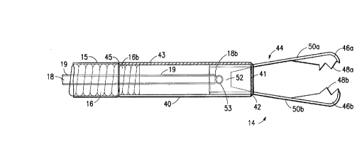
Turning now to Figures 2 through 5, the end effector 14
includes a partially conductive cylindrical sleeve 40 having a
~preferably sharp) distal edge 42, and a conductive jaw assembly
44. The jaw assembly 44 includes a pair of opposed jaw cups 46a,
46b each preferably having a plurality of sharp teeth 48a, 48b.
A resilient, preferably narrow, arm 50a, 50b extends proximally
from each jaw cup 46a, 46b. A cylindrical base member 52 joins
the proximal ends of the arms 50a, 50b. The narrow resilient
arms 50a, 50b are biased apart from each other, thereby urging
the jaw cups 46a, 46b apart. According to a preferred embodiment
of the invention, the cylindrical base member 52 of the jaw
assembly 44 is mechanically and electrically coupled to the
uninsulated distal end 18b of the control wire 18 by providing
the base member 52 with a lateral hole 53 and providing the
distal end 18b of the control wire with a substantially right
angle bend. The distal end 18b o~ the control wire 18 is
soldered or otherwise electrically and mechanically attached in
the hole 53 in the base member 52. The cylindrical sleeve 40 is
coupled to the uninsulated distal end 16b of the coil 16 by
crimping and/or soldering. According to this embodiment of the
invention, the partially conductive sleeve 40 has a first
conductive area in the form of a ring 41 near the distal edge 42
and a second conductive area in the form of a longitudinal stripe
43 which extends from the ring 41 to the proximal end of the
sleeve 40. The proximal end 43a of the stripe 43 is electrically
coupled to the distal end 16b of the coil 16, preferably by
soldering. Optionally, a third conductive area 45 is provided on
the proximal edge and interior of the proximal end of the sleeve
40 and makes electrical contact with the distal end 16b of the
coil 16. It will be appreciated that the conductive ring 41 is
CA 02242897 1998-07-10
W097/2499S PCT~S97/00494
therefore electrically coupled to the coil 16 via the stripe 43,
and optionally the third conductive area 45.
From the foregoing description those skilled in the art will
appreciate that when the spool 22 and the shaft 20 are axially
displaced relative to each other, the cylindrical sleeve 40 and
the jaw assembly 44 are similarly axially displaced relative to
each other, from the positions shown in Figure 2 to the positions
shown in Figure 3 and vice versa. It will also be appreciated
that when the spool 22 and shaft 20 are in the approximate
position shown in Figure 1, the cylindrical sleeve 40 and the jaw
-assembly 44 will be in the approximate position shown in Figure
2; i.e., with the jaws open. Thus, those skilled in the art will
~urther appreciate that when the spool 22 is moved towards the
thumb ring 24, or vice versa, the cylindrical sleeve 40 and the
jaw assembly 44 will be brought into the approximate position
shown in Figure 3 by movement of the jaws into the sleeve,
thereby closing the jaws.
It will also be understood that one pole of a bipolar
cautery source (not shown) which is coupled to the electrical
connector 27 will be electrically coupled to the ring 41 on the
sleeve 40 via the coil 16 and another pole of the bipolar cautery
source which is coupled to the electrical connector 35 will be
electrically coupled to the jaws 46a, 46b via the control wire
18. Since the jaw assembly 44 never comes in contact with the
conductive portions 41, 43, 45 of the sleeve 40 ~ring 41 being
separated from the jaws by the non-conductive distal edge 42) and
since the control wire 18 is insulated from the coil 16 by the
sheath 19, short circuits are avoide lring all phases of the
biopsy procedure. When cautery curr - is supplied to the end
effector asse~bly 14, if tissue is p ~nt at the edge 42,
current passes between the conductive ring 41 and the arms 50a,
50b or the jaws 46a, 46b via the tissue (not shown) depending on
the position of the jaw assembly 44 relative to the sleeve 40.
According to one embodiment of the invention, the sleeve 40
is made of a non-conductive ceramic material and the conductive
CA 02242897 1998-07-10
W O 97/24995 PCT~US97/00494
areas 41, 43, and optionally 45 are applied by tracing with a
conductive material. For example, the conductive material may be
applied by vapor deposition, thermal spray, or other means of
metalization onto a ceramic sleeve where the sleeve is first
masked to cover areas which will remain non-conductive.
According to another em~odiment of the invention, sleeve 40
is made of aluminum which is then anodized. Prior to anodizing
the sleeve, portions of the sleeve are masked so that they will
remain conductive after the unmasked portions of the sleeve are
anodized.
Turning now to Figures 6-8, according to a second embodiment
of the invention, an end effector assembly 114 is coupled to the
distal ends of the coil 16 and control wire 18. The end effector
assembly 114 is similar to the end effector assembly 14 described
above in that it includes a cylindrical sleeve 140 and a jaw
assembly 144. The jaw assembly 144 is substantially the same as
the jaw assembly 44 described above, with similar reference
numerals indicating similar parts. In this embodiment, however,
the cylindrical base 152 of the jaw assembly 144 is mechanically
and electrically coupled to the distal end 16b of the coil 16 by
crimping and/or soldering. The cylindrical sheath 140 is also
similar to the cylindrical sheath 40 described above having a
(preferably sharp) distal edge 142, a conductive ring 141 near
the distal edge 142, and a conductive stripe or portion 143 which
extends proximally from the conductive ring 141. In this
embodiment, however, the sleeve 140 is electrically and
mechanically coupled to the distal end 18b of the control wire
18. The coupling is effected by providing a lateral hole 147 in
the sleeve 140 and a right angle bend in the distal end 18b of
~ the control wire 18. The end of the control wire is inserted in
the hole and is soldered or otherwise mechanically and
electrically connected to the sleeve. As seen in Figures 6-8 the
conductive portions 141 and 143 of the sleeve 140 make electrical
contact with the distal end of the control wire 18 via the hole
147.
CA 02242897 1998-07-10
W O 97n4995 PCTrUS97/00494
It should be appreciated that when the endoscopic instrument
with the jaw assembly 114 is actuated, the sheath 140 will be
moved by the control wire 18 over the arms 150a, 150b and jaw
cups 146a, 146b. Because the arms are narrow, there is
sufficient room for the right angled bend in the insulated wire
18 to extend between the arms and out to the sheath 140 without
contact being made between the wire and the arms. In addition,
if desired, the connection between the control wire and the
sheath can be made more proximally along the sheath to avoid
contact between the control w~re and biopsy samples collected
between the arms.
There have been described and illustrated herein several
embodiments of an endoscopic bipolar multiple sample bioptome.
While particular embodiments of the invention have been
described, it is not intended that the invention be limited
thereto, as it is intended that the invention be as broad in
scope as the art will allow and that the specification be read
li~ewise. Thus, while particular configurations of the handle
have been disclosed, it will be appreciated that other types of
handles could be utilized. Also, while specific couplings of the
ends of the coil and control wire have been shown, it will be
recogni7ed that other types of couplings could be used with
similar results obtained. Moreover, while particular
configurations have been disclosed in reference to the jaw
assembly, it will be appreciated that other con~igurations could
be used as well. For example, while it is preferred to provide
~aws with teeth, it will be appreciated that in lieu of teeth,
the jaws can be provided with sharp edges which, in conjunction
with a sharp cylindrical sleeve, will provide a cutting ability.
Furthermore, while the jaw assembly has been disclosed as being
formed from Nitinol, it will be understood that different
formations of the jaw assembly can achieve the same or similar
function as disclosed herein. Further yet, it will be
appreciated that while the apparatus of the invention was
described as advantageously permitting the obtaining of multiple
biopsies without removal from the surgical site, the apparatus of
the invention, if desired, could still be used for obtaining
CA 02242897 1998-07-10
W O 97/24995 PCT~US97/00494
11
single biopsies at a time. With regard to the partially
conductive sleeve, it will be appreciated that the arrangement of
the conductive portions may be varied considerably so long as the
conductive portions of the sleeve do not contact the jaw
assembly. It will therefore be appreciated by those skilled in
the art that yet other modifications could be made to the
provided invention without deviating from its spirit and scope as
so claimed.