Note: Descriptions are shown in the official language in which they were submitted.
CA 02243262 1998-07-1~
CONCAVE BLADE MANUAL RETURN i\/IEASURING TAPE
-
BACKGROIJND Al~D SU~vIARY OF THE INVENTION
Concave blade tape measures are commonly used by those in the construction and
contracting trades because the stiffness of the concave curved blade allows one person to
manipulate the blade for a variety of layout and measuring tasks. Concave tape blades are
cornmonly found in power return tape measures having spring motors to rewind the tape
blade. A difficulty with concave tape blades is that winding a concave blade in a coil
produces spring forces that distort the coil. As a result, power return tape measures are
generally limited to about 30 to 35 feet of tape length. In the construction trade, it is
10 frequently necessary to lay out wall stud pattems of fifty feet, which renders a measuring
tape shorter than 50 feet long inconvenient.
The invention is directed to concave blade tape measures that can be made in
lengths greater than 30 feet. More particularly, the present invention is directed to a
concave blade tape measure having a manual return mech~ni~m
A tape measure in accordance with the invention includes a case or housing made
of three parts, a right shell, a center tubular spacing member. and a left shell, that are
fastened together to define an interior space. A mouth for the tape blade is formed in the
spacing member near the bottom of the case.
According to the invention, a tape blade is wound on a winding reel supported for
20 rotation in the case. The reel includes a core to support the wound tape, and a flange
member adjacent the core and supporting a side of tape blade to facilitate winding into a
core.
The reel also includes a flange and a boss projecting from the flange. The boss is
positioned to extend through a hole in the right side shell with the flange disposed on an
inner face of the right shell. A crank for tuming the winding reel is attached to the boss.
A friction ring is disposed bet ~een the flange and the inner face of the right shell
to provide friction to resist rotation of the winding reel caused by spring energy stored in
the wound tape blade which urges the blade to unwind.
CA 02243262 1998-07-1~
The opening in the tubular spacer for the tape blade includes a lip that engages a
- portion of an end hook on the tape to releasably secure the end hook to the case, which
also prevents the tape blade from unwinding of the tape blade.
- The crank is pivotably mounted on the boss, and has a closed or folded position
and an extended or unfolded position. In the closed position, a leg of the crank projects
away from the boss which provides an access point for pressing the crank to move it to
the unfolded position.
BRIEF DESCRIPTION OF THE DRAWINGS
The invention will be better understood by reference to the following detailed
description in conjunction with the appended drawings, in which:
Figure 1 is a perspective view of a measuring tape in accordance with the
invention;
Figure 2 is a right side view of the measuring tape of Figure 1 with the right side
shell removed to illustrate the interior;
Figure 3 is a right side view of the tape measure of Figure 1;
Figure 4 is a side view of a winding reel for the measuring tape blade;
Figure 5 is a view of an interior of a left side shell of the measuring tape of Figure
l;
Figure 6 is a front view of a friction ring;
Figure 7 is a side view of the friction ring of Figure 6;
Figure 8 is side view of a tubular spacing member; and
Figure 9 is a front view of the spacing member of Figure 8.
DETAILED DESCRIPTION
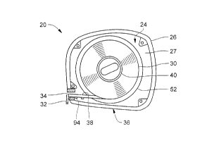
A manual return tape measure 20 in accordance with the invention is illustrated in
perspective view in Figure 1. The tape measure 20 includes a case 22 having a right side
shell 24, a tubular center member 26 and a left side shell 28 fastened together to define a
CA 02243262 1998-07-1~
closed interior for housing a measuring tape wound on a reel. The terms "right" and
"left" are used for convenience in the description, and indicate a reference direction for
typical use of the measuring tape in which the right side of the case will face the right
hand of the user.
Figure 2 shows the tape measure 20 with the left side shell 28 removed. A
concave blade measuring tape 30 is wound on a core 40 inside the case 20 with an end
hook 32 e~cten~ling from an opening 34 near the bottom 36 of the case. By concave blade
is meant a strip of material that is curved along a long aYis to have the f~mili~r trough
shape, being concave on one side and convex on the opposite side. The blade 30 is
10 positioned so that the concave side 38 faces upward, that is, away from the boKom 36,
when the blade extends from the case.
The tape 30 is wound on a ~vinding reel 50, which is illustrated in front view in
Figure 3 with the right side shell 24, and in Figure 4 in side view removed from the case
20. The winding reel 50 includes the core 40 and a flange 52 integrally attached to the
core. The flange 52 provides a guide during winding to help wind and m~int~in the tape
blade in the cylindrical core. The core 40 includes a hole 42 in which the end of the tape
blade 30 is inserted and secured. A raised boss 54 projects from the flange from a side
opposite the core 40. The boss 54 includes a stepped front face, having a first portion 56
that projects farther from the flange 52 than a second portion 58. A well 55 is formed in
20 the boss 54 in the first portion 56.
The winding reel 50 is disposed in the case 20 with the boss 54 projecting through
a hole 25 in the right side shell 24 (Figure 3) and the flange 52 positioned on an inside
face of the right side shell 24 (Figure 2). The core 40 abuts a bearing 44 mounted or
forrned on the left side shell, illustrated in Figure 5. The bearing 44 includes a flat disk
portion 46 against which the end face of the core 40 rests and a raised circular collar 48
that is received in the core to support the core during rotation.
A crank 60 is mounted in the well 55 in the first portion 54. The crank 60 is
pivotable bet veen a folded position (shown in Figure 1) where it is received in the well
55, and an e~ctended position for tuming the winding reel 50, shown in Figures 3 and 4, in
30 which the cranlc is disposed ourvard and away from the boss 54. The crank 60 includes a
CA 02243262 1998-07-1~
knob 62 for manipulation of the crank. A crank arm has a dog-leg shape, with a first leg
64 attached to the boss 54 by pins 65. A second leg 68 extends at an angle from the first
leg 66. A leaf spring 70 formed in the well 55 and cooperates with flat surfaces of the
first leg 64 for releasably holding the crank arm in any of three different positions,
including the folded and extended positions, and an upright position where the crank is
substantially perpendicular to the boss 54. When the crank 60 is in the folded position,
the first leg is parallel to the boss 54, as shown in Figure I and in ghost in Figure 4, and
the second leg 68 is oblique to the boss. In the extended position, shown in Figure 4, the
second leg 68 is parallel to the boss 54 and the first leg extends obliquely. This extended
position advantageously spaces the crank knob 62 away from the case 20 and the boss 54
to facilitate m~nll~lly tuming the crank to rewind the measuring tape blade.
As seen in Figure 1 and Figure 4 in ghost, the second end 68 of the crank in thefolded position is positioned at the junction between the first 56 and second 58 portions of
the boss. The second end 68 projects above the junction and provides an easily accessible
point on which pressure (from a thumb or finger) can be applied to pivot the crank from
the folded position to the extended position. The jutting out position of the second end 68
is advantageous when the user is wearing work gloves, which is typical in the
construction trade.
As can be seen in Figure 2, the tape 30 wound on the core 40 is flattened, which20 transfomms the concave curvature into elastic energy that tends to cause the coil of tape to
distort. The degree of distortion is proportional to the length of measuring tape (and
hence the amount of stored energy) and the size of the core on which the blade is wound.
In power return tape measures, which have large inner cores to accornrnodate the retum
spring, the distortion in tapes longer than about 30 to 35 feet can render the power retum
mechanism inoperable.
Another characteristic of wound, metal tapes is that winding the tape around thecore 40 a,Yis stores up spring energy that tends to cause the tape to unwind. Ifunconstrained, the wound tape 30 in the case 20 would unwind through the opening 34.
The tape measure 20 according to the invention includes two features to prevent
30 unwanted un-vinding of the coiled tape 30. Figure 6 and Figure 7 illustrate two views of
CA 02243262 1998-07-1=,
a friction ring 80 that is disposed between the flange 52 of the winding reel 50 and the
inner face 27 of the right side shell 24. The friction ring 80 is formed of spring steel in a
ring shape having an undulating profile, illustrated in Figure 7. The ring 80 iscolllplessed between the flange 52 and the right side shell 24, and provides sufficient
- friction therebetween so that rotation of the winding reel 50 from spring energy of the
wound tape blade 30 is avoided. The tape blade 30 will not unwind from the case 20
without an extemally applied force, and will remain at any position to which the blade is
exten-le~l Other friction rings, for example, a cork ring or a ring having a prepared,
roughened surface, could be used as alternatives.
Figure 8 shows a side view of the center tubular member 26 removed from the
case 20. The tubular member 26 spaces the right shell 24 and the left shell 28 a distance
apl~fop~iate for the width of the tape blade. In addition, the tubular member 26 includes
the opening 34 through which the tape blade extends. Figure 9 is a front view of the
tubular member 26 showing the opening 34. The opening 34 includes a hole 90 shaped
with a curvature to approximate the curvature of the convex side of the blade. The
opening 34 also includes a lip or edge 92 on an inner side of the opening that engages a
portion of the end hook 32 to releasably secure the end hook to the case 20. As seen in
Figure 2, the end hook 32 is fastened to the tape blade 30 with rivets 94 that extend
through the blade and end hook. When the tape blade 30 is wound fully on the core 40,
the rivets 94 are disposed inside the case 20, and the spring energy of the wound tape
blade urges the tape against the opening and the lip 92. The rivets 94 thus catch on the lip
- 92, preventing the tape blade 30 from moving through the opening 34 until the rivets are
lifted above the lip.
The center tubular member 26 is made of a material such as nylon that is resistant
to cuts from the long edges of the tape blade running against it while being pulled from
the case and rewound into it.
According to another aspect of the invention, the bottom 36 of the case 20 is
shaped to rock slightly. As seen in Figure 5, a main part 37 of the bottom 36 issubstantially flat, and a front part 39, as indicated by the broken line, is oblique to the
main part and directed toward the opening 34. The extended tape blade, because of
CA 02243262 1998-07-1~
spring energy in the wound blade and the orientation of the bottom of the coil to the
opening, is angled toward the top of the opening 34, away from the boKom 36 of the case
20. The extended tape is thus not parallel with the bottom of the case, which could cause
difficulty in m~kin~ measurements. Ch~nging the orientation of the entire bottom wall 36
would cause the case to rest on the end hook 32 when the tape is fully wound.
According to the invention, when the tape is fully wound in the case, the case will
naturally rest on the major part 35. When the tape blade is extended about two feet, the
weight of the extended blade causes the case 20 to rock onto the front part 39 of the
boKom 36, which in turn causes the blade to tilt downward until the end hook rests on the
10 horizontal surface, thus facilitating measurement.
The invention has been described in terms of preferred embodiments, principles
and structure. Those of skill in the art will recognize that substitutions can be made
without departing from the scope of the invention as defined in the claims.