Note: Descriptions are shown in the official language in which they were submitted.
CA 02243417 1998-11-16
EI763697437US
Title: REMOVABLE DISPLAY SURFACE
TECHNICAL FIELD
The invention relates to a removable display surface for use as a cover to a
beverage container; more particularly, it relates to a removable and precisely
measured independently resilient cover for reusable beverage containers with a
promotional or advertising message printed on the cover.
BACKGROUND OF THE INVENTION
Many kinds of containers, and particularly beverage containers, are placed in
public view, both commercially and privately used, and therefore are
appropriate for
use as display surfaces for various kinds of advertising and promotion.
Commercially,
beverage containers are on display containing coffee and other beverages;
privately,
thermos bottles may be viewed by others while in use, both by way of example.
The
container wall itself however is ill suited to a display surface as it readily
becomes
marred and disfigured, and the printing matter itself is degraded, so that any
such
display is a poor display indeed for the subject matter of the advertisement
or
promotion. As yet however, no feasible and effective display surface has been
proposed which may be attached to these beverage containers or other
containers so
~0 as to adequately address the needs of current advertising and promotional
standards.
In recent years, it has come to be recognized that old style coffee warmers
and
open coffee pots are not in the best interests of the delicate flavor
characteristics of
CA 02243417 1998-11-16
a good brew of coffee. To that end, vacuum pots of various shapes and
descriptions
have become increasingly popular and prevalent, especially in finer commercial
coffee
houses and restaurants. Such a pot preserves desirable coffee serving
temperature
with reduced risk of, and exposure to, either burner heat scorching or air
oxidation
of the coffee esters. They also generally hold more coffee, and can be made
available
for use and refills by customers in places that are not wired or not safe for
warmer
burners.
As mentioned, these pots are often highly visible to the customers and could
become effective sign boards for the brand of coffee or any other advertising
an owner
may wish to display in conjunction with the service of the coffee or other
beverage.
However, with the passing of time and customer use and normal wear and tear
(such
as by dish washing operations), the vacuum pots themselves can take on
unsightly
dents and surface mars.
It has been suggested to permanently adhere a surface covering that is
specially cut to fit the pot to the outside of the pot. This covering can hold
or display
various advertising or promotional messages and graphics. These covering
systems
however suffer from several disadvantages. Because they are permanently
adhered
to substantially the entire outside surface of the pot, they in effect become
a second
skin, and as such lose much if not all of the independent resiliency such a
covering
material might otherwise inherently have. Any blow or other force striking the
skin
will be transmitted to the pot as well, and any resulting deformation in the
pot
surface will also show on the tightly adhered covering skin. Also, if the
advertising
message becomes stale or otherwise out of date, or if the covering begins to
show
signs of wear or other distress, it must laboriously be removed in its
entirety, leaving
the pot covered in unsightly adhesive residue until it is recovered, and this
operation
must be repeated every time it is desirable to change the advertising message.
2
CA 02243417 2004-02-19
77720-1
Other proposed covering systems require application of a heat shrinkable film
to a container, with the disadvantages that such films are not readily, and
certainly
not non-destructively, removable, and rather less control of the kind and
quality of
printing that may be imprinted on the film, vn its resultant resized surface,
is
possible compared with unshrunk covers.
Other covering system proposals disclose (1) a foam rubber beverage can
insulator with flexible sidewall and bottom member with slits on the bottom
for
expansion and contraction; (2) a wastebasket, or other open container, cover
with a
flexible sheet to wrap around the side wall of the basket, and clips to
detachably
interconnect the top and bottom edges of the sheet to the open rims of the
container,
and Velcro type closures to hold the ends together; and (3) a loose $tting
sock-like
covering to fit over standing water cooler bottles and the like, or s free
standing
cylinder of rigid material resting on the cooler apparatus, with holes or
viewing ports
to show water level and provide air circulation inside the covering.
What is needed is a feasible and effective display surface- which may be
attached to beverage containers or other containers so as to adequately
address the
needs of current advertising and promotional standards: In addition, it would
be
desirable for such a display surface to be easily and readily removable and to
possess
independent resiliency land not be just a second skin tight layer). The
desired
'?f) removable display surface would require only cover end attachment by
releasable
closures, and would provide an excellent base medium for commercial printing
processes.
SUMMARY OF THE INVENTION
Accordingly, it is an object of the invention to provide a feasible and
effective
'?a display surface which may be attached to beverage containers or other
containers so
as to adequately address the needs of current advertising and promotional
standards.
*Trade-mark 3
CA 02243417 1998-11-16
It is a further object of the invention to provide in such a display surface
an
easily and readily removable wrap around cover.
It is another object of the invention to provide a wrap around cover having
independent resiliency.
It is another object of the invention to provide a removable display surface
requiring only releasable closures for attachment together of its cover ends.
It is another object of the invention to provide a removable display surface
in
turn providing an excellent base medium for commercial printing processes.
It is yet another object of the invention to meet any or all of the needs
summarized above.
These and such other objects of the invention as will become evident from the
disclosure below are met by the invention disclosed herein.
The invention addresses and overcomes these difficulties by providing a
method for making a precisely measured cover for reusable beverage containers.
A
covering of independently resilient material is precisely cut to fit a given
size and
shape of pot, and the material has imprinted on it a desired promotional or
advertising message and/or graphics. The covering material is removably
fastened
to the outside of the pot in such a way as not to impair significantly the
natural
resiliency of the material. For instance, in one embodiment the covering is
fastened
to the pot by means of temporary fasteners such as Velcro~ type hook and pile,
magnets, removable tape, or the like. 'Thus, dents in the pot do not generally
show
in the covering surface because it retains its independent resiliency, even if
the blow
was delivered through the covering surface. Messages may be changed as often
as
suits the promotional and decorative needs of the owner of the pot, so the
display
surface is always timely and in top condition. An optional "window" permits
display
of interchangeable labels on the inside of the covering. When the display
surface is
4
CA 02243417 1998-11-16
fully removed, the original surface of the pot is substantially restored to
its former
appearance. Some of the covers are to be transparent or translucent and are to
have
graphic images back printed on them. Optionally, a protective plastic covering
or
overlaminant is attached to the print side of the covering material, so that
when the
printed cover is in its removed state, the printing will not be accidentally
damaged
by scratching. Some embodiments employ a nylon fabric cover material with
promotional printing.
The invention provides a flexible, removably fastened, precisely fitted
container
cover having a graphical display imprinted on one side of the cover. The
graphical
display may be advertising or promotional text and/or non-textual graphical
images.
The flexibility of the container cover material is to facilitate ready
application,
removal and reapplication of the container cover to the same or different
containers,
as often as may be necessitated by the need, for instance, to replace a worn
or
damaged cover, or to provide a different promotional message. By "precisely
fitted"
is meant that each cover is measured and cut to substantially exactly fit a
particular
container or identically sized series of containers, where "fitting" means to
substantially completely cover the side walls of the container, generally
without
overlap. In some instances however, some overlap may be advantageously
provided
for the purpose of providing a fastener mounting surface to facilitate that no
fastener
parts need be attached in any way to the container itself. It will be
appreciated by
those skilled in the art that variations of this dimensioning and fitting may
be
effected to no particular purpose but to avoid the above definition, in which
case such
variations are to be regarded as within the scope of this invention.
Generally, this
invention will find application as a covering for beverage containers of the
type used
to serve coffee in public establishments; however, the invention is not
limited to such
a particular container.
5
CA 02243417 1998-11-16
Some embodiments of the invention will include a transparent window in the
cover, through which a "label" may be viewed through the window. A window is
preferably a transparent region of the cover on which no graphic display has
been
imprinted, but may in some embodiments be effected with a separate transparent
material sewn in or otherwise assembled into the cover material itself. A
"label" can
either be an actual label, such as the name of the blend or beverage being
dispensed
from the container, or it can be any additional supplemental promotional
graphical
display information. The label is generally disposed over the window in such a
way
that the graphic material on the label can be viewed through the window, and
the
label is preferably attached to the window with a removable pressure sensitive
adhesive. However, it will be appreciated that any conventional means for
holding
a piece of material on which can be printed some graphical information, such
as an
open ended clear envelope attached to one side of the container cover can
advantageously be employed to make the label viewable through the window.
Preferred embodiments will have the label holder on the inside or rear surface
of the
container cover where it may readily be accessed by removing the cover,
inserting or
replacing the label and reattaching the cover. This arrangement will provide
both
protection for the label, and facilitate integration of the label into the
overall
graphical design of the cover.
Some embodiments of the invention will be made of a durable, preferably
washable, woven fabric such as nylon ripstop or cordura, and the graphical
display
is generally imprinted on a front surface of the cover material ("front
printed"). Such
embodiments may be removed for cleaning as well as for replacement to display
different promotional messages. This embodiment will also be especially
resistive to
displaying or revealing any surface imperfections of the container itself, and
will be
better able to resist impact damage to the cover material itself. Preferred
6
CA 02243417 1998-11-16
embodiments will have a second, or inner, fabric layer preferably made of a
more
tightly woven polyester material for additional resiliency and insulating
value.
Other embodiments of the invention will be made of a resilient translucent
material, such as clear plastic sheet, with the graphical display imprinted on
a rear
surface of the cover ("back printed") to better protect the printing itself.
Various
materials may be employed such as printing grades of Lexan~ brand plastic
sheeting
and various vinyl sheet materials and all such plastics as will be known by
those
skilled in art to take and retain a high quality graphical imprint. It will
generally not
be necessary to take any special precaution or apply any selection criteria
relating to
heat shrinkability, or thermal stability, as the covering material will
generally be
removed from the container prior to exposing the container itself to high
temperature
washing or sterilization. While thermally unstable material will therefore
generally
not be preferred, its use will not depart from the scope of the invention.
Some embodiments will also employ an overlaminant layer disposed to cover
the graphical display imprinted on the rear surface of the clear plastic
sheet. Since
some embodiments have no attachment whatever of the cover to the container
itself,
other than that provided by the relatively tight "wrap" of the cover on the
container
and the attachment of one edge of the cover to itself, it is anticipated that
some
sliding of the cover as wrapped around some of the containers will produce
some
z0 chaffing or wear of the back printed matter, and possibly some
discoloration or
staining of the surface of the container itself. Even without such sliding,
the removal
and replacement of the printed covers will leave the printing exposed to
possible
damage while the cover is off the container. To forestall any such damage to
the
printing, an overlaminant layer may be advantageously applied over the
printing to
seal it from such damage. This layer will preferably be laminated to the cover
material by methods well known to those in the art, but may also be adhesively
7
CA 02243417 1998-11-16
adhered to the printed side of the cover material, or attached in any other
way as
may seem useful to those skilled in the art.
The overlaminant layer may be clear also, but may also be opaque or even
metalized (such as for instance a sheet of aluminized mylar) to provide
insulation to
the container.
The removable fastening of the cover to the container may be effected by one
or more releasable closures. A preferred releasable closure is a paired
arrangement
of hook and pile closures respectively attached to opposite ends of the cover
material.
They may be disposed as single strips along the end (adjoining) edges of the
cover, or
as spaced closure tabs along the adjoining edges of the cover. Alternatively,
part of
the closure pair may be attached to the container itself to forestall sliding
of the cover
on the container, and the opposite closure type may be attached to one or both
ends
of the cover for removable fastening of the cover to the container.
Alternatively, the releasable closures may be paired magnetically active
materials, such as two compatibly poled magnets, or a magnet and a strip of
ferrous
material. For ferrous bodied containers, it may only be necessary to provide a
magnetic strip, or magnetic tabs (as described above) along adjoining edges of
the
cover for magnetic attachment of the cover to the container by the magnets.
For non-
ferrous container, including some stainless steel types, paired magnets, or a
magnet
and steel strip combination, will be employed and attached to the cover as
described
above for hook and pile closures for attaching the cover to the container. In
some
embodiments, at least one part of the pair of magnetic materials is comprised
of a
magnet strip and the other part of the pair of magnetic materials is a ferrous
container surface to which the magnet strip is attracted. In other
embodiments, the
pair of magnetic materials is comprised of a pair of magnet strips
magnetically
attracted to each other.
8
CA 02243417 2003-07-23
77'720-1.
The invention gener:~a:l:iy pr~oc,r:Lde::a a removable wrap
around container cover of ~nater:ial pzv.~wi.d.ing independent
resiliency. By "i.ndependent. resilaenc~~~r" ~.t is generally
meant that: the mal~er_al x-e.E:errv~d t.~> t.tn.zsljr :is capable of
sustaining an impact, and even of transmitting that impact
through to the underlying ~.-~or~t:air~.er~, Sa.Ener:~c, the impact might
cause surface damage to the container sucha as a dent, but
whereby material :is ~_~apablc~ cat r~F-ebou:r;c:Y:i..nc:k to or resuming its
previous shape resiliently so t:rmat: tnc>_ c~c>wer materia::L does
not betray the damage to th.e container. beneath. One way to
acY~.ieve ox- pr_eser~re t: hi.s inde~enc:~erzt .~::v.~s:z. ierzcy is to
forebear to adhere the cover material x..n any substantial way
to the container ~Lt:;c~l f .
Preferred embodiments of the invention will also
have at least one guide s:lc~t aruca tab ~aix with the t~.~b on
one end of the cover and the slot: near t:o, or proximate, the
opposite end of they cover G~nd ~~eruer~a:~ ~ ~r a~. igried with it:s tab
mate in a generally paral:Le:_ wa~,r. ~ s;a..ot is proximate an
end of the cover material t:o the extent.. that there is
generally not more:' of the c:.c7vex rruat~eri~i~l. between the slot or
slots and the end than is useful. to preserver the physical
integrity of the s1c>t:s triernsel.4Te:~~; on t~Ya.e c-,ne hand, a~°nd
than
is useful to ef.fec.~.t a mating Gayex°, fc.~r: use when an optional
adhesive material is provided on tree contacting surface of
one or both of the' s:l. ot/-~~.aYa p~:~:i r so tr.rzG~.t the tab ( s;i a:~nd
mating layer may both or singly be pressed in the di:rection
of the container t:o k5e~ re:~rnc°ma~~:E.~~~ ~.~dhex:f:,.d. to the
ecwe:r:.
material to form a secure but remoT.rabl.e: cover attachment .
Therefore, accordi_nE.~ t:.c.:~ :::r ba~c:~ad a.spect~, t~hc
invention provides a flexible, removably fastened, pwecisely
fitted container cower h<:~.vi.rrg :~ g:r:~~~p.t~u_c~al. display imY~7ri.nted
thereon.
ca
CA 02243417 2003-07-23
77 720-1
According to another broad aspect, the invention
provides a flexible, rern.covabl..r° f,xstenc=~,,i, precisely fitted
container cover havirng a graprrical. displa~vr imprinted. on a
rear surface ther~~o:~, wher~eir~ thc~~ cont~:~in~:ar cover is
comprised of a resilient traryslucent p:~.ast;i.c sheet, the
cover further compri sing a tr:a.ns~:~arerlt: w:x_r~dow and a :Label
disposed on one side of the window so that :it may be viewed
through tree other side of the wit~.dow, a:md further cornp:risi.ng
one or more releasable closures where cacti closure is
further comprised of at i east. ca:rz~.=. pair ofi magnetical:Ly
active materials, and wherein the cover i5 removably
fa:~tenable to a container wi.t.tv t:r~ue c:Lo~~uxve s .
According to a fzzrther broad aspect, the invention
provides <~ container cover comp:rv. sin~:~ <.r f~.exible sheet with
a graphical display imprinted the::reon, anc:i a cover fastener
for removably fastening th~~ c,wer °::o c~ cor..tai.ner, the
fastener comprising one or rnor.e releasabi.E: closures, the
releasable closures compxi;~:~ng a:at. Least: or:~e pair of
magnetically active rnatex-ials, arnd fux:~t.her wherein tie sheet
is adapted to substantiall,,r cwex~ ~-~he~ si.de walls of the
container.
According to a further broad aspect, the invention
provides a cantairzen cover corn~>x-:i. ~.~ in<:.~ ~~, f 1 exible she~,t with
a graphical display imprinted thereon, and a fastener
whereby the cover may be rerr~oved a:x:-orn a container, arid
further wherein the sheet vs adapted fi.c> substan~iall°y cover
the side walls of a c.~onta~.ner.
According t;o a. ft.zrther.~ .broad ~~;~pect, the i~:nve~ntion
provides a method of removably~c~overing a container, the
method comprising px~ecis~~ly c~.ztt:i~zg arzci. fitting a .flc~xi.ble
sheet to fit a given size and shape of container, imprinting
a graphical image on the sr~ee~~., a:r~zd r..emovably wrapping the
Ja
CA 02243417 2003-07-23
77'720-1
sheet around the side walls c::~fthi.e con~:~a.~r~ez~ and fastening a
releasable closure operably associated wit::h the sheet to
hold the sheet :in place c:~n trice cc,~r~~tai.n~~r.
According t:o a furt:rre:r l;>raad asi.>ect, th.e invention
provides a container cover ccmpri.sing a dear plastic sheet
with a graphical display impz::i citc~:d on ,:~ rear surface
thereof, and a cover fastener faz:~ remavab:Ly fastening the
cover to a container, and furt.hle.r.~ whe:r~:~irr the sheet. is
adapted to substantially saver faze sicica walls of the
container.
ACCOrdlllg t::o a furt.:r3.c:,r broad as~..>ect, the invention
provides a container cover comprising a f~,~.exible sheet with
a graphical displ<~y imprinted thereon, acrd a cover .fastzener~
whereby the cover may be removed from a container, and
further wherein the sheet: i;~ adapted t:c:> ma.bstantially cover
the side walls of a container, the saver further comprising
a window :i.n the cover than :is t:~rt:a:nsp,:z:~.-e::~nt throe gh the cover,
and a label disposed on the window to k.3e viewed through the
window.
According to a further broad aspect, the irmention
provides a container cover comprising ~~ fl.exible sheet with
a graphical display :i.mpri.rrted t:&ner~=_orl, ur~c~ a cover fastener
for removably fastening the cover to a container, and
further wherein the :sheet. :is adapted t.:c:' ~;ubstanr_i~ally cover
the side walls of the container, where~_n the cover fastener
comprises one oz' mare releasab:l~:~ cl.osvzr:~e:~ and at lea,~t one
of the releasable clasures is further comprised of a guide
slot and tab pair, wherein t:hr~ t:;,r~.b is orz c~rre~ end o:E the
cover and the slot is proximate the apposite end of the
cover and paralle7_ t.c> the t::ab, t:kue ga.zi.c;ie ~l.ot and l~a~~ pair
further comprising adhesive material ar: the contacting
surface ofat 1_ea~~t one ~oax~t~ c:oa t:.i-rc: ~~u:i..de slot and t,:zb pair.
:~ L
CA 02243417 2003-07-23
77720-1
BRIEF DES~'RTPTI~N GF THE DR~W:INGS
Figure 1 is a schematic rear plan view of the
invention.
Figure 2 is a schenuat icv rear plan view of an
alternate embodiment of t~.:he a nVezW aora..
Figure 3 :is a part:i.ai c~.r.Toss ~:~ec:r::i.on. of 'the
invention taken at line 3-3 of Figure 3.
Figure ~4a-c is a schematic p~rrt~al cross section
of the invention.
9 c:
CA 02243417 2004-02-19
77720-1
Figure 5 is a partial cross section of an alternate
embodiment of the invention.
Figure 6 is a front perspective elevation of the
invention.
Figure 7 is a partial perspective view of an aspect
of the assembly of the invention.
Figure 8 is a partial schematic cross section taken
along line 8-8 of Figure 1.
Figure 9 is a partial schematic cross section taken
along line 9-9 of Figure 7.
Figure 10 is a schematic rear plan view of an
alternate embodiment of the invention.
Figure 11 is a cross section taken along line 11-11
of Figure 10.
Figure 12 is a typical accommodation in the precise
fit of the cover for the container.
BEST MODE OF CARRYING OUT THE INVENTION
Turning now to the drawings, the invention will be
described in a preferred embodiment by reference to the
numerals of the drawing figures wherein like numbers indicate
like parts.
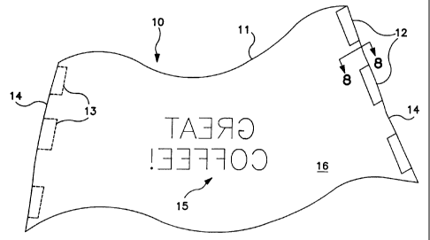
In Figure 1 removable display surface 10 is
comprised of independently resilient cover 11 and releasable
closure or fastener pairs 12, 13, where fastener half 12 and
fastener half 13 are generally matable or detachable halves of
a releasable closure system pair, such as for instance a hook
and pile type closure or paired magnets. It will be
appreciated that in many instances, the halves are
CA 02243417 2004-02-19
' ~ 77720-1
interchangeable, which is not to say identical, but rather
that part 12 may be either a "hook" strip for instance or a
"pile" strip, and vice versa for part 13. In general, one
half of the closure will be on one cover end 14 and the other
half will be on the other cover end. In the case of hook and
pile closures, fastener half 12 will preferably be on the rear
surface 16, while fastener half 13 will be disposed on the
front surface 17 of cover 11. Thus, as cover 11 is wrapped
around container 80 (see Figure 6), halves 12 and 13 are able
to engage each other and removably fasten cover 11 to
container 80.
l0a
CA 02243417 1998-11-16
In this embodiment, though the cover is precisely fitted to its intended
container or container series, that fit is accommodated at least in part by a
careful
overlap of ends 14 to the extent necessary to effect the releasable engagement
of
fastener halves 12 and 13. It should be noted that halves 12 and 13 are
illustrated
as groups of separate strips; however, it will be advantageous in some
applications
to have fastener half 12 be a single long strip covering substantially the
width of
cover end 14, and the same will be true for fastener half 13. Where a
plurality of
strips is employed, the respective mating opposite pair halves will be aligned
so that,
upon mating engagement, the cover is closed without appreciable skew in the
mating
of cover ends 14; that is, a cover 11 cut to cover a cylindrical container,
for example,
will close into a cylindrical shape, with ends 14 overlapping (where such
overlap is
required by the nature of the fastener) and more or less congruent. In Figure
6,
display surface 10 is wrapped around container 80 so that fastener halves 12
and 13
engage their respective mates in the direction indicated by the arrows after
cover
ends 14 overlap.
The cut of cover 11 is also effected to accommodate the shape of the intended
container, whether it be cylindrical or frusto-conical or other shape. Both
Figure 1
and Figure 2 illustrate covers cut to accommodate a frusto-conical container.
In
Figure 1, the pronounced "waviness" of the top and bottom edges of cover 11
are
intended to illustrate the relatively more flexible nature of the woven fabric
embodiment, as opposed to the relatively more rigid plastic sheet embodiment
of
Figure 2. However, the aspect of back printing of graphical message 15 onto
the rear
surface 16 of cover 11 is arbitrarily illustrated in Figure 1, notwithstanding
that
fabric embodiments of the invention will generally not be translucent to any
appreciable extent and will rather be front printed. By the same token, the
"window"
aspect of the invention illustrated in Figure 2 by window 19 and label 18 may
be
11
CA 02243417 1998-11-16
advantageously employed in either the sheet or fabric embodiments of the
invention,
though illustrated arbitrarily only in Figure 2.
Figure 12 illustrates a typical accommodation in the precise fit of cover 11
for
its container. In the example case of a beverage container/dispenser having a
conventional glass fill gauge and a pour spigot beneath, cover 11 is relieved
by cut
out 5 so that display surface 10 covers all of the sidewall surface of the
container.
Optional hook or pile fastener halves 26 are appropriately placed to mate with
corresponding and respective pile or hook fastener halves affixed to the
container
itself.
Figure 8 illustrates and alternative construction for cover 11 in Figure 1.
Instead of one layer of fabric in cover 11, two layers are sewn together:
inner layer 31
and outer layer 32. Preferred outer layer (also preferred in there is only one
layer)
material is style 2020 200 denier ripstop nylon; inner layer material is
preferably
style 6000 600 denier polyester fabric.
In Figure 2 a plastic sheet embodiment of the invention is illustrated.
General
Electric Lexan~ brand plastic film is preferred in this embodiment, though
printing
grades of vinyl sheeting may also be made to serve. For the sake of simplicity
of
illustration, closure halves 12 and 13 are not shown; however, it is to be
understood
that the releasable fasteners described in reference to Figure 1, or their
equivalents,
may be employed in any other embodiment, whether illustrated or not. Label 18
is
preferably disposed on or over transparent window 19 in cover 11 so that a
message
(not shown) on label 18 disposed on the rear surface 16 of cover 11 may be
viewed
through window 19 from the front surface 17 of cover 11. This arrangement is
shown
in partial cross section in Figure 3.
Label 18 is preferably attached to the rear surface 16 of cover 11 and over or
behind window 19 with a pressure sensitive removable adhesive so that labels
of
differing message content may be interchangeably disposed behind window 19
from
12
CA 02243417 1998-11-16
time to time without damage to cover 11 and without need for alternative label
attaching means. Alternative label attaching means may however be employed
without departing from the scope of the invention. Mounting label 18 behind
window 19 provides the protection of a covering window to the various labels
that
may be placed behind any particular window. In practice, it will be a simple
matter
to open cover 11, remove a label, and replace it with a new label. It has been
found
that Flexcon (Seattle, Washington) V400 frosty clear V68 removable pressure
sensitive adhesive adequately adheres label 18 to any part of rear surface 16,
including window 19, while providing ease of removal of label 18 when it is
time for
replacement. Preferred label material is Flexcon 90 PFW vinyl.
Figures 4a-c schematically illustrate the quality of independent resiliency of
the invention. In Figure 4a container wall 80 is obscured by cover 11. The
cover
appears smooth and unbroken to the viewer. In Figure 4b an impact force 99
strikes
both cover 11 and, through it, to container wall 80, causing a dent 81. If
cover 11
were permanently adhered, or even adhered at all to wall 80, dent 81 would
show to
some extent in cover 11. This would also be true in other conventional
covering
systems. But in Figure 4c, cover 11 appears much as it did before the impact
of
force 99, thus obscuring dent 81 and other surface imperfections in container
wall 80.
This might not hold true for forces and impacts from sharp objects whose
effect is to
cut or tear cover 11, but for most relatively dull impact forces short of
those tending
to destroy the container itself, cover 11 will merely transmit such forces,
not be
changed by them.
In Figure 5, an alternate embodiment of the sheet plastic embodiment is
illustrated in schematic partial cross section. Cover 11 is back printed with
ink 22,
except in the region of window 19. Over the ink layer is preferably disposed
overlaminant 21. Overlaminant 21 provides enhanced resiliency to cover 11 and
protects ink 22 from abrasion against container 80 and from accidental damage
while
13
CA 02243417 1998-11-16
cover 11 is removed, as for example when the container is being washed. For
embodiments not employing an overlaminant, conventional UV hardening inks may
be employed, and if protection from abrasion is desired without using an
overlaminant, then an air cure texture coat of Deco-Chem 7030 abrasion matt
small
text may be applied to the back of the back printed graphic ink layer.
In the case of overlaminant, conventional inks are preferred, as it has been
noted that UV inks tend to release to the overlaminant and cause flaws or
bubbles
to appear from the front of the cover. Preferred overlaminant material is
Flexcon
Flextwin MM-200 white/white metalized mylar adhered to the cover sheet layer
with
TC-249, V-29, 1504-9 adhesives or their equivalent. These adhesives provide a
white
backing layer to obviate the need otherwise for a white coat behind the
graphic
display ink. Alternatively, vinyl sheeting may also be used for the
overlaminant
layer.
Figure 10 shows an alternate configuration of the invention. Curved
window 19 is set amid cover 11 of display surface 10. Preferred magnetic
closures 41
and 42 in the form of cover end width rubberized magnetic strips are adhered
to the
rear surface 16 of cover 11 proximate the respective cover ends 14. In some
embodiments (not shown), magnetic strips 41 and 42 lie at or very near the
cover
ends and the cover is wrapped around a container having ferrous material walls
so
that the magnets adhere magnetically to the container walls, and the fitted
cover 11
fits precisely around the container without overlap, the magnets maintaining
both
closure of the seam whereat the two cover ends meet, but also thereby holding
the
cover to the container. This configuration is advantageous for ferrous bodied
containers. For non-ferrous bodies and some types of stainless steel, it is
desirable
for the magnet pair to be disposed for mating engagement with each other
through
self adherence.
14
CA 02243417 1998-11-16
As these arrangement will sometimes permit slippage of cover 11 both with
respect to its grip on container 80 and also with respect to its own precise,
unskewed
alignment of its cover ends 14, especially in smooth or relatively featureless
containers, the embodiment illustrated in Figure 10 is preferred. In this
embodiment,
alignment tabs 23 and slots 24 are provided. Some overlap is provided to
effect the
engagement of respective corresponding slots and tabs, and the positioning of
the
magnets 41 and 42 is adjusted, with magnet 41 near the tab end of the cover
being
preferably quite close to, but not overlapping, the tabs, and with magnet 42
being
inside the line of slots 24, rather than being so close to the other end 14 of
cover 11,
as shown. In this configuration, as cover 11 is wrapped around its container
(such
as is shown in Figure G), tabs 23 come into engagement with and through slots
24,
thereby assuring complete and correct alignment of ends 14; at the same time
the
magnets 41 and 42 adhere to container 80 and releasably hold cover 11 to the
container.
Figure 11 shows a schematic cross section for the preferred placement of
magnets 41 and 42. As they are intended to adhere, not to each other, but to
the
container, they are place on the same (inner) side of cover 11. As an
alternate
arrangement, providing for magnet-to-magnet engagement, magnets 41' and 42'
are
shown positioned on opposite sides of cover 11, and with magnet 42' shifted
relative
to the position of magnet 42 to be more proximate the cover end 14, where
magnet
42' is disposed between the cover end 14 and the line of slots 24, so that,
with
appropriate overlap of cover ends 14, magnet 41' may engage magnet 42' when
cover 11 is wrapped around its container. Tabs 23 have a roughly pointed and
stepped design to facilitate insertion into slots 24.
Figures 7 and 9 illustrate a variation on the guide tab and slot configuration
of Figure 10; Figure 7 also shows the wrapped engagement of tabs 23 into slots
24.
The alternate embodiment requires no hook and pile or magnet fasteners, but
rather
CA 02243417 1998-11-16
relies on the application of removable pressure sensitive adhesive 25 to the
underside
of tabs 23 and to the flap end of cover end 14 that lies between the cover end
and the
line of slots 24. After tabs 23 are fully inserted into slots 24, adhesive 25
is activated
if required (such as by removing any protective non adhesive strip or strips),
and the
tabs and the flap end are all pressed inward (in the direction shown by the
arrows)
against wrapped cover 11 to securely, but releasably fasten cover 11 around
container 80. This configuration is particularly well suited to wrap covers
for
children's containers which must endure rugged usage, such as thermoses.
With regard to systems and components above referred to, but not otherwise
specified or described in detail herein, the workings and specifications of
such systems
and components and the manner in which they may be made or assembled or used,
both cooperatively with each other and with the other elements of the
invention
described herein to effect the purposes herein disclosed, are all believed to
be well
within the knowledge of those skilled in the art. No concerted attempt to
repeat here
what is generally known to the artisan has therefore been made.
INDUSTRIAL APPLICABILITY
A feasible and effective display surface which may be attached to publicly
placed beverage containers or other containers is needed to adequately address
the
needs of current advertising and promotional standards. Such a display surface
is
most valuable if it is easily and readily removable and possesses independent
resiliency. Advertising may be changed often, and the owner of the containers
is
never embarrassed at the physical condition of the containers themselves,
covered as
they are by the display surface.
In compliance with the statute, the invention has been described in language
more or less specific as to structural features. It is to be understood,
however, that
the invention is not limited to the specific features shown, since the means
and
16
CA 02243417 1998-11-16
construction shown comprise preferred forms of putting the invention into
effect. The
invention is, therefore, claimed in any of its forms or modifications within
the
legitimate and valid scope of the appended claims, appropriately interpreted
in
accordance with the doctrine of equivalents.
17