Note: Descriptions are shown in the official language in which they were submitted.
CA 02243453 2000-02-08
CRIMPER ASSEMBLY
The present invention relates to a crimper assembly or crimper machine
for crimping a workpiece, for example, crimping a fitting ferrule to a hose.
Crimping
assemblies or crimping machines for crimping fittings to hoses are well known
in
the art. One such prior art crimper is disclosed in U.S. Patent No. 5,257,525.
Other types of crimping assemblies or crimping machines are shown in prior art
patents Nos. 4,034,592; 4,034,593; 4,400,967; and 4,785,656.
The present crimper assembly is particularly useful in crimping hose
fittings in the field. Sometimes it is necessary to connect, for example, a
hose
fitting ferrule to a flexible hose which is designed to carry gases. In this
situation,
it is important that the crimper assembly be capable of providing a tight
sealed
crimp which does not release gas to the atmosphere.
One problem in prior art crimper machines was the difficulty in
disassembling the crimper assembly or crimper machine to quickly replace the
die
segments, when necessary. This is often necessary where various diameter
fittings
or fitting ferrules are being crimped and the dies or die segments must be
quickly
replaced.
One object of the present invention is to provide an improved crimper
assembly which is readily disassembled for the interchange of the die sets.
The present invention is directed to a crimper machine or crimper
assembly for crimping a workpiece, such as a hose fitting ferrule to a hose.
The
crimping assembly includes a pair of tie rods having different diameters which
mount a lower stationary die carriage and an upper movable die carriage. A
central
rod is mounted on the movable carriage and extends through a press bar. A
driving
force is applied to the central rod by either a cylinder or by an impact
wrench to a
screw, connected to the central rod.
Die retainer plates are attached adjacent receiving cavities defined by
the carriages and include guide slots. Tongues are provided on flexible die
set
retainers which are positioned within the receiving cavities. When in the
correct
position, the tongues extend into the guide slots and hold the die set
retainers in
their correct position.
-1-
CA 02243453 2000-02-08
A spring biased disconnect plate is slidably attached to the tie rods
adjacent the press bar. When the disconnect plate is moved to a disconnect
position, the movable carriage can be moved along the tie rods for access to
the
flexible die set retainers and the die sets.
According to an aspect of the present invention, there is provided a
crimping assembly for crimping a fitting ferrule to a hose comprising: (a) a
stationary die carriage having a pocket for receiving crimping die sets; said
stationary die carriage defining spaced apart first and second receiving
cavities
disposed parallel to each other with said pocket disposed therebetween; (b) a
pair
of parallel tie rods fixedly supported, one in each of said first and second
receiving
cavities; (c) a movable die carriage having spaced apart passageways slidably
receiving said tie rods; (d) a press bar mounted on said tie rods, said press
bar
having first and second side openings, each receiving one of said tie rods and
a
central aperture positioned therebetween; (e) a central rod extending through
said
central aperture and movable therethrough toward and away from said stationary
die carriage, said central rod having an attachment end secured to said
movable
die carriage; (f) a first die set retainer plate attached to said stationary
die carriage,
said first die set retainer plate having a slot, a first flexible die set
retainer
positioned in said stationary die carriage adjacent said first die set
retainer plate,
said first flexible die set retainer having a tongue received in said plate
slot and
crimping die sets received in said first flexible die set retainer; and (g) a
second die
set retainer plate attached to said movable die carriage, said second die set
retainer plate having a slot, a second flexible die set retainer positioned in
said
movable die carriage adjacent said second die set retainer plate, said second
flexible die set retainer having a tongue received in said plate slot and
crimping die
sets received in said second flexible die set retainer.
Figure 1 is a front elevational view of a crimper assembly, according to
the present invention;
Figure 2 is a rear elevational view of the crimper assembly shown in
Figure 1, with the movable die carriage moved to its down position;
Figure 3 is an exploded view of the crimper assembly shown in Figure
1;
_2_
CA 02243453 2000-02-08
Figure 4 is a top elevational view of the crimper assembly shown in
Figure 2, shown on a reduced scale;
Figure 5 is a fragmentary right end view of the crimper assembly shown
in Figure 2;
Figure 6 is a fragmentary rear elevational view of the crimper assembly
shown in Figure 2 with a portion shown in cross-section;
Figure 7 is a cross-sectional view taken along the line 7-7 of Figure 1
and showing a fitting ferrule positioned between the movable and stationary
die
carriages prior to crimping;
Figure 8 is a view similar to Figure 7 showing the ferrule after crimping;
Figure 9 is a fragmentary front elevational view, similar to Figure 1
showing another embodiment of a crimper assembly, according to the present
invention; and
Figure 10 is a fragmentary view of another embodiment showing a one-
piece stop plate adjacent the lower stationary die carriage.
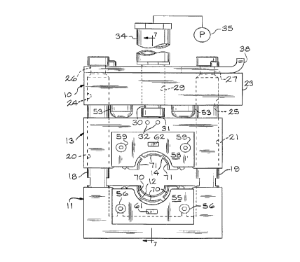
Referring to the drawings, a crimper machine, according to the present
invention, is generally indicated by the reference number 10. The crimper
machine
or crimper assembly 10 includes a lower stationary die carriage 11 having a
pocket
12 and an upper movable die carriage 13 having a mating pocket 14.
The stationary die carriage 11 includes spaced apart first and second
receiving cavities 16 and 17 which receive and mount the lower ends of a pair
of
parallel tie rods 18 and 19. Preferably, the tie rod 19 has a larger outer
diameter
than does the tie rod 18. The movable die carriage 13 has spaced apart
passageways 20 and 21 for slidably receiving the tie rods 18 and 19. The
passageway 21 is of a slightly larger diameter than the passageway 20. The
difference in diameter of the passageways 20 and 21 and the corresponding tie
rod
diameters 18 and 19 ensure that when the slidable, movable die carriage 13 is
removed from the tie rods 18 and 19, for example, when the die sets are
removed,
the movable die carriage 13 is not improperly reversed when it is repositioned
on
the tie rods 18 and 19.
A press bar 23 defines openings 24 and 25 which receive the upper
ends of the tie rods 18 and 19. The upper ends of the tie rods 18 and 19
define
-3-
CA 02243453 2000-02-08
reduced diameter portions 26 and 27. The press bar 23 also defines a central
aperture 29 which receives a central rod 30. The bottom of the central rod 30
has
an attachment end 31 which is secured to the movable die carriage 13 by roll
pins
32. The upper end of the central rod 30 is operatively connected to the rod of
a
cylinder 34. In the present embodiment, the cylinder 34 is a hydraulic
cylinder and
is supplied by a hydraulic pump 35. In other embodiments, the central rod 30
is
driven by an air cylinder (not shown) or by a screw as discussed subsequently.
A disconnect plate 37 is slidably mounted adjacent the top of the press
bar 23. The disconnect plate 37 has an upturned end 38 which is used to grasp
the
plate 37 for movement. Referring to Figure 3, the disconnect plate 37 also
defines
first openings 39 and 40 which are complementary with and receive the reduced
diameter portions 27 and 26 of the tie rods 19 and 18. A second connected and
larger opening 41 extends from the first opening 39 and a second larger
opening
42 which is a connected end slot extends from the first opening 40. When the
crimper assembly 10 is in its operating position, the disconnect plate 37 is
positioned so that the first openings 39 and 40 receive the complementary
reduced
diameter portions 27 and 26 of the tie rods 19 and 18. When it is desirable to
remove the movable die carriage 13, the upturned end 38 is grasped and the
disconnect plate 37 is moved to align the tie rods with the second opening 41
and
the second opening or end slot 42. The movable die carriage 13 can then be
removed from the tie rods 18 and 19. This operation is normally used when the
die
sets are changed.
Referring to Figures 3 and 6, the upper surface of the press bar 23
defines a pair of parallel slots 44 which receive springs 45. One end of each
of the
springs is connected to the press bar 23 by pins 46 and the other end is
connected
to the disconnect plate 37 by pins 47. The springs 45 act as a spring assembly
which is operatively connected between the disconnect plate 37 and the press
bar
23 to urge the disconnect plate 37 to the crimper assembly operating position
wherein the first openings 39 and 40 within the disconnect plate 37 receive
and are
aligned with the reduced diameter portions 26 and 27 of the tie rods 18 and
19.
The disconnect plate 37 is slidably positioned on the press bar 23 by a
plurality of cap screws 49 which extend through a plurality of longitudinally
-4-
CA 02243453 2000-02-08
extending slots 50 in the disconnect plate 37 and are received in threaded
openings
51 in the top of the press bar 23.
I n the present embodiment, elastomeric bumpers 53 are mounted on the
bottom of the press bar 23, as shown in Figure 1. As the movable die carriage
moves upwardly when the central rod 30 is retracted, the movable die carriage
13
can engage the bumpers 53.
Referring to Figures 1-3, a first die set retainer plate 55 is attached to the
stationary die carriage 11 by cap screws 56. A second die set retainer plate
58 is
attached to the movable die carriage 13 by cap screws 59. An important feature
of the crimper assembly 10 is that the first die set retainer plate 55 defines
a guide
slot 61 and the second die set retainer plate 58 defines a guide slot 62.
A first flexible die set retainer 64 is positioned within the pocket 12 of the
stationary die carriage 11 and includes a plurality of openings 65 and an
outwardly
extending tongue 66. Similarly, a second flexible retainer 67 having a
plurality of
openings 68 and an outwardly extending tongue 69 is positioned within the
pocket
14 of the movable die carriage 13. The first and second flexible retainers 64
and
67 are preferably constructed of a flexible plastic material and their
openings 65
and 68 receive a plurality of individual die sets 70 and 71. The tongues 66
and 69
are received in the guide slots 61 and 62, respectively. If the respective die
sets
70 and 71 are prepositioned in the first and second flexible retainers 64 and
67, the
die sets 70 and 71 may be quickly removed and replaced as entire sets when a
new size is required. It has been found that the guide slot and tongue system
makes the interchanging of die sets more efficient than what was known in the
prior
art.
In some embodiments, not shown, die set retainer plates similar to the
plates 55 and 58 are positioned on the opposite sides of the stationary die
carriage
11 and movable die carriage 13. However, in the present embodiment, a die set
retainer plate 73 is mounted by cap screws 74 to the opposite side of the
movable
die carriage 13. A stop plate assembly 76 is mounted by cap screws 77 to the
opposite side of the stationary die carriage 11. The stop assembly 76 includes
an
inner plate 78 having a recess 79 and an outer plate 80 having a curved
portion 81
for supporting a workpiece during the crimping operation.
-5-
CA 02243453 2000-02-08
Referring to Figures 7 and 8, in a normal crimping operation, a workpiece
comprising a hose fitting 84 including a ferrule 85 is positioned within the
crimper
machine 10. The end of a flexible hose 86 is positioned within the ferrule 85.
The
cylinder 34 is energized. The attached central rod 30 and the connected
movable
die carriage 13 are moved downwardly. The die sets 70 and 71 engage the
ferrule
85 and crimp the ferrule 85 into a tight sealed relationship with the hose 86,
as
indicated in Figure 8. The movable die carriage 13 is then moved upwardly, the
completed crimped hose assembly removed and another cycle begun.
Referring to Figures 9 and 10, another embodiment of a crimper
machine or crimper assembly 10, according to the present invention, is
generally
indicated by the reference number 90. In this embodiment, a threaded central
rod
91 having a hex head 92 at its upper end is mounted for movement in a threaded
opening 93 defined through the press bar 23. A lower end 94 of the central rod
91
is connected to the movable die carriage 13 as described above with respect to
the
first embodiment. When the crimping assembly 90 is used, rather than a
cylinder
operation, as discussed with respect to the crimper assembly 10, an impact
wrench
is mounted on the hex head 92 and the central rod 91 rotated to move the
movable
die carriage 13 downwardly to perform the crimping operation.
Referring to Figure 10, the crimper assembly 90 includes a one-piece
stop plate assembly 96. The stop plate assembly 96 includes a stop plate 97
which
is connected to the stationary die carriage 11 by cap screws 98. The stop
plate 97
includes a curved portion 99 which supports the workpiece, such as the ferrule
of
a hose fitting during the crimping operation.
Many revisions may be made to the above-described embodiments
without departing from the scope of the present invention or from the
following
claims.
-6-