Note: Descriptions are shown in the official language in which they were submitted.
CA 02243496 1998-07-17
WO 9712682]L PCT~lJS97~111I3
I~vIPROVED STAIN RE.~IOVAI DEVICE
FIELD OF THE INVENTION
The present invention relates to devices which can be used to remo-e stains
from ~brics. The devices are especially useful as part of a dry cleaning operation.
10 but can also be used under any ~ es where spot removal from fabrics is
desired.
BACKGROUND OF THE INVENTION
By c~SCc;cs~l ~lcfinition, the term "dry cl~nin~" has been used to describe
processes for cleaning textiles using nonaqueous solvents. Dry cleaning is an old art.
with solvent clP~nin~ first being l~eG.ded in the United Kingdom in the 1860's.
20 Typically, dry cleS~ning processes are used with ~ such as woolens which are
subject to shrinkage in aqueous l;-~ .g baths, or which are judged to be too
va~uable or too ~ ic-sltp to subject to aq~leo~c l,.. ~ processes. Various
hydroc.arbon and haloc~ul~n solvents have t~iitiQnS lly been used in ;.. ~ ~ion dry
cle~ning ~l~ces~s, and the need to handle and reclaim such solvents has mainly
25 ~ ic~d the pl~ e of CO.1~ ;O~AI dry cleA~ to co,~ ial establichmentc
Wh;ile solvent-based dry rleAning ~n~.ce,~s are quite effective for removing
oiiy soils and stains, they are not optimal for .e.llo./in~, particnl~tes such as clay
soils, and may requi~c special h~ t con~iitionc to remove plot~ eouc stain~
Ideally, par~irnl~s and p,vt. ;~ e~ua stains are removed from fabrics using
30 d~.t~ ivc ingredients and op~ cQn~littinwhich are more akin to aqueous
1~.1..~. ;.-~ plOCCSS~S than to con~ ..l;on~l dry rk~-~;J~
In addition to the cleSnin~ function, dry cleSnin~ also provides hlll~OIL;~llt
"rc~ rl~S. For cA~hn~le~ dry cleSlning removes unde~ ble odors md
CAt[al~C~ matter such as hair and lint from ~ c which are then generallv
- 3~ ~olded or pressed to remove wrinkles and restore their original shape. Of course.
such rcLcit....- .l benefits are also afforded by aqueous laundering processes.
CA 02243496 1998-07-17
W Q 97/26821 PCT~US97/01113
As can be seen ~rom the foregoing. and aside from the effects on certain
fabrics such as woolens. there are no special. inherent advantages for solvent-based
irnmersion dry c~eaning over aqueous cleaning processes with respect to fabric
cleaning or refreshment Moreover. on a per-~arment basis. commercial drv cleaning
5 is much more e~cpensive than aqueous cleaning processes. Accordingly. it would be
of considerable benefit to consumers to provide non-immersion dry cleaning
processes which can be used in the home.
One type of home dry cleaning system comprises a carrier sheet Cont~ining
various cleaning agents. and a plastic bag. The garments to be cleaned are placed in
10 the bag together with the sheet, and then tumbled in a conventional clothes dryer. In
a commercial embodiment, multiple single-use flat sheets and a single multi-use
plastic bag are provided in a package. Unfortunately, such processes may not
satisfactorily remove stains from heavily soiled or "spotted" areas of the fabrics
being drv cleaned. .
As is well known, heavily stained garments may be "pre-spotted" using so-
called "spot removal" compositions prior to cle~ning. However, it has now been
noted that such methods typically involve the vigorous back-and-forth rubbing of the
garment with a cle~ninp composition and a towel, sponge or other implement. It has
now further been detenninecl that such rubbing can cause fabric damage and
2Q excessive wear.
By the present invention, a device is provided which allows the user to pre-
spot fabrics without resort to rub~ing. The device herein loosens and removes stains
via controlled m~orll~nical action, thereby avoiding fabric darnage. As will be seen
hereinaf~er, the device is (lesi~n~c~ to gently implement Z-axis m~ch~nics only, with
respect to the ~abric being treated.
BACKGROU'l~D ART
A peracid-cont,.inin~ dry cleaning composition is described in U.S.
4,013,575, issued to H. C~ c, et al., March 22, 1977. Dry cleaning processes
are disclosed in: U.S. 5,547,476, issued to Siklosi and Roetker; EP 429,172AI,
pu~lished 29.05.91, Leigh, et al.; and in U.S. 5,238,587, issued 8/24/93, Smith, et al.
Other references relating to dry cleaning compositions and processes, as well asw~inkle tr~tmentc for fabrics, include: GB 1,598,911; and U.S. Patents 4,126,563~
3,g49.137, 3,593.544, 3,647,354; 3,432,253 and 1,747,324; and German applications
2,021,561 and 2,460,239, 0,208,989 and 4,007.362. Cleaning/pre-spotting
compositions and methods are also disclosed, for example, in U.S. Patents
5.10 ',573: 5~041,230; 4,909~962; 4,115~061; 4,886,615; 4,139,475; 4.849.257;
5,112.358; 4~659,496; 4,806~254; 5,213!624; 4,130,392; and 4.395,261. Sheet
CA 02243496 1998-07-17
W O 97/26821 PCTAUS97/01113
substrates for use in a laundrv drver are disclosed in C~n~Ai~n 1.005.2W. U.S.
3,9~6.~56 and ~}.007.300 relate to perforated sheets for fabric conditioning in a
clothes dr~er. U.S. 4.697~77 discloses the use of I .~-octanediol in liquid cleaners.
See also U.S. Patents 3.591,510; 3.737,387. 3.764.544; 3.882,038; 3.907,496;
4.097,3~7; ~,102.824. 4.336.024; 4,594~362; 4.606,842; ~,758.641; 4.797,310;
4,802~9~7; 4,943,39~; 4,966,724; 4,983,317; 5,004,557; 5,062 973; 5~080,822;
5,173,200; EP 0 ~13 500; EP0 261 718; G.B. 1,397,475; WO 91/09104;
WO 91/13145; WO 93/25654 and Hunt, D.G. and N.H. Morris, "PnB and DPnB
Glycol E,thers", HAPPI. April 1989, pp. 78-82.
SUMMARY OF THE INVENTION
The present invention encomp~c~ a fabric cleaning device, comprising:
(a) a base member having a convex front tre~tment face and a rear face
oppositely disposed from said tre~tment face;
(b) one or more tre~tmt?nt members e~tl~n~lin~ outwardly from said
tre~tmPnt face; and
(c) optionally, a hand grip affixed to said rear face.
A p~ d device herein is inten-l.ofl for hand-held use, although the devices
can be ernployed in co~ .c.~;ial mechanical eqllipmP~t if desired.
In one embodiment, the circumference of the base member of the device is
20 subst~nti~lly circular. In one aspect of this type of device the convex front treatment
face is substantially ht~n~i~phprical~ or is a convex section of a hemisphere.
In another embodiment of the device, the base member is arcuate, and the
convex -front tre~tmPnt face is arcuate.
The ~ m~mher used on the device can be absorbent, such as a
2~ sponge. Preferably, in any of the devices herein, the lle~l ~ef member comprises a
mllltiplicity of protrusions, such as bristles. Most preferably, the tre~fm~nt member
comprises a sponge layer affixed to said convex lle~ -t face, said sponge layer
having a multiplicity of protrusions t?xten~ling outwardly thc,~r,u~
ln a p-~:r~lled embodiment, the hand grip (c) comprises a shaft e~t~n(1ing
ouhvardly from the rear face of said base member. Optimally, the shaft extends
substantially from the center of the rear face. Most preferably, the shaft is
sllhst~n1i~1ly perpendicular to the rear face. In a convenient mode, the distal end of
said shaft terrnin~tt?s in a bulb, thereby providing gripping means for the hand of the
user.
There is thus provided a method for removing stains from a stained area of
fabrics using a device according to the invention~ c~ isillg the steps of:
(a) applying a spot cleaning composition to said stained area;
CA 02243496 1998-07-17
W O97/26821 PCTrUS97/01113
(b) concurrently or consecutive~y with Step (a), contacting the stained
area of the fabrics with the treatment members of said device: and
(c) applying force to said device, preferably by means of a rocking or rolling
motion imparted to the device.
S The process herein can be cnn~ cte~l in conJunction with a receptacle
situated beneath the stained area of the fabrics, whereby a saturated or partially
saturated environment is achieved. In another mode the process is conducted in
conjunction with an absoll~el.l stain receiver (especially a FAM foam, as described
more fully hereinafter) which is sitll~t~c~ beneath and in contact with the stained area
10 of the fabric.
The invention also provides an overall non-immersion cleaning/l~l~~
process for treating a stained fabric, which comprises a prespotting operation
employing a device according to the invention and comprising the overall steps of:
(a) applying a spot cle~ninp composition to said stained area;
(b) concurrently or consecutively with Step (a), contacting the stained
area of the fabrics with the ~ r,~ mPmhers of said device;
(c) applying force to said device;
(d) placing the prespotted fabric together with a carrier cont~ining an
aqueous cleaningll~Ç~ nt composition in a cont~inm~nt bag;
(e~ placing the bag in a hot air clothes dryer and operating the dryer with
heat and tumbling; and
(f) removing the fabric from the bag.
In a highly plc;fe~ d mode, the process is con~ tefl in a manner such that vapors are
vented from the bag during step (e).
The device herein can also be used in an overall laundering process which
involves treating a stained area of fabric, which comrri~es a l~lejyulLillg operation
employing a device according to the invention, and comprising the overall steps of:
(a) applying a spot cle~ning composition to said stained area;
(b) COnCUL~ IY or consecutively with Step (a), cont~rting the stained
area of the fabrics with the tre~tmPnt m~mbPrs of said device;
(c) applying force to said device; and
(d) laundering the fabrics in a conventional aqueous laundering process.
The invention also provides a drv cleaning kit, c~-mrri~ing:
(a) a device according to the invention;
(b) a re-usable co~ ont bag;
(c) multiple, single-use sheets cO~ g a cleaning/refr~chment
composition;
CA 02243496 1998-07-17
WO 97/26821 PCTnJS97~1-13
(d~ optionally. a re-usable holding tray; and
~e) optionally? one or more absorbent stain receivers as described
hereinafter.
In a preferred mode. the invention also encompasses the device which has
usage instructions on said device to discourage the use of a side-to-side scrubbing
motion with said device.
l hese and other embo~im.onrc of the invention are provided herein. as will be
seen from the following disclosures.
All pelc~ ges, ratios and p,opollions herein are by weight, unless otherwise
specifiecl. All doc~lm~ntc cited are, in relevant part, incorporated herein by reference.
BRI~F VESCRIPTION O~ THE DRAWlNGS
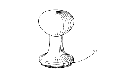
Figure 1 is a perspective of the cleaning device herein having a convex base
(301) whose circumference is suhst~nti~lly circular.
Figure 2 illustrates a bi-lobal, or generally dumbbell-shaped device of the
present ~ype. This type of device can optionally be fitted with different types of
tre~tm~n,t mennh~rs, thereby allowing a dual choice between gentle and norrnal
cle~nin~
Figure 3 is a p~,-a~e-;Live of the assembled arcuate cleaning device (201)
herein.
Figure 4 is an exploded view of the device showing the arcuate base (202),
shaft (203) and bulb (204) which comprise the hand grip assembly separated from
the sponge layer (205) and the layer of fibrous protub~ ces (206) which perform
the cleaning function.
Figure ~ is a pc;la~e~ e of a device of the present type being used to spot
treat stains (207) using hand pressure. This illustration shows a holding tray placed
beneath the fabric being treated.
Figure 6 illustrates a cle~ning device having an arcuate ("rocking horse")
fimrtion~l base (208) according to this invention, with a hand grip (209) which is
hollow lo provide a reservoir for a spot cle~n;n~ composition, and with a dispensing
3û means (210) l~,cessed into the hand grip shown in a closed configuration.
Figure 7 shows the dispensing means (210) opened to dispense the spot
cleaning composition.
1 igure 8 shows another embodiment of a hand grip/reservoir device with the
arcuate cleaning base and with a ~licp~on~ing means (211) shown in an open
3~ configuration and positioned to allow dispensing onto the stained fabric during use.
l~igure 9 is another embodiment of a reservoir device.
CA 02243496 1998-07-17
W O 97126821 PCT~US97/01113
Figure 10 is another embodiment showing an ergonomically useful hand grip
(21~) on an arcuate cleaning device.
Figure l 1 is a perspective of a cleaning/refreshing sheet ( 1 ) of the type used
herein.
Figure 1~ is a perspective of the sheet loosely resting on a notched. vapor-
venting cont~inment bag which is in a pre-folded condition.
Figure 13 is a perspective of the sheet within the bag which is ready to
receive the fabrics to be treated in a hot air clothes dryer.
Figure 14 is a partial view of the notched wall of the bag and its disposition
relative to the closure flap.
Figure 15 is a perspective of an un-notched vapor-venting bag cont~ining a
cleaning/refre~hmcnt sheet.
Figure 16 is a graph of water venting from a vapor-venting "Envelope"-style
Bag with the vapor-venting closure, from a Standard Bag, i.e., a sealed bag without
the venting closure (as control for comparison purposes); and from an "Envelope
Bag (2)" which has a vapor venting closure at each end.
Figure 17 is a graph of water venting as in Figure 16, expressed in grams.
Figure 18 is a graph which shows the relationship between OlJ~.d~ g regions
of the present process with respect to fabrics wherein Wrinkles Form, Unwrinkled,
Wrinkles Removed, and Wrinkles Not Removed.
Figure 19 is a perspective of an especi~lly plcf~lcd arcuate device
comprising cleaning protuberances (401), sponge layer ~402), arcuate base (403),shaft (404) and bulbous hand grip (405).
It will be appreciated from the disclosures herein that the present invention
2~ provides the user with various options for cleaning and ~cfl.,sllhlg fabrics, especially
g~ P.~t~, in a simple, readily available aplJd~dLus such as a conventional hot air
clothes dryer. In a p~cfe~lcd embodiment, the user is provided with an article which
comprises an absc"l,cl,l core which releasably contains a c~ ning/lcrl~ nt
composition. It is highly ~cr~ d that this core with its load of liquid composition
30 be s~lbst~nti~lly enrobed in an outer cover sheet, most p,c~.~bly a "formed-film"
which has openings through which the composition is permeable in the vapor state,
but which col1sliluLes a barrier through which liquid can flow in, but would be
~c~l~di,led in the core against flow outward. An encasement of the liquid-filled core
can also be composed of a low-density batting of non-water absorbent fiber such as
35 nylon. polyester, polypropylene and the like. In addition, the user can, optionally,
also be provided with a separate portion of a spot removal ("pre-spotting")
composition.
CA 02243496 1998-07-17
W O 97~26821 PCTAUS97~1I13
When treating a fabric (such as a soiled. ~Tinkled or malodorous garment) in
the present manner. the item is first inspected for hea-ily spotted areas. When
heavily spotted areas are found. it is preferred to treat them individually before the
"in-drver" step of the overall process. In order to conduct this pre-spotting step. the
5 user has several choices, as follows.
(,4) The spots can be individually treated with conventional spot
removers using conventional implements such as brushes. sponges, and the like.
~his is ~ot pl~r .l~d since conventional solvent-based spot removers can cause dye
damage ~nd leave residues on fabrics. Moreover, brushing with a conventional side-
10 to-side ~X-Y plane) motion can cause fabric darnage.
(:B) The spots can be individually treated by laying the spotted area of the
fabric over the article herein and pressing downward (Z-direction) with the convex
device of this invention as described more fully hereinafter. This pressure on the
fabric causes a portion of the liquid cleaning/refreshment colllpo~ilion to surge into
15 the fabric at the ~ ule point, thereby effecting localized stain removal. The fabric
and the ele~nin~/refr.ochment article are then placed in the cont~inment bag andtreated in the dryer.
~ 3 In a third option, the user is provided with a separate portion of a pre-
spotting composition. In-use, this is directed onto the stained area of the fabrics, and
20 worked-in using the convex cleaning device of this invention. Optionally, the fabric
being treated can be situated over and in contact with a stain receiver or otherabso.l,el}t material during this step. This option has the advantage that the liquid
composition used in the pre-spotting step can be fo~ tecl dirr~.e.~tly from thatused in ~:he in-dryer step. For exarnple, the pre-spotting composition can optionally
25 contain higher solvent levels than the in-dryer composition. Or, the pre-spotting
composition can contain peroxides, surfactant levels, and the like, which are sub-
optimal for use in the in-dryer step. ~Itern~tively, the pre-spotting and in-dryer
compositions can be the same. ~Iowever, the forrnulator has more degrees of
freedom when op~ldling in this manner. After this pre-spotting step, the fabric and
30 cle~ning/l -rl. il,l,.~nt article are then placed loosely in the co~ ;I"~e~t bag and
tumbled together, preferably in a hot air clothes dryer.
DETAILED DESCRIPTION OF THE INVENTION
The components of the devices of this invention and their method of use are
described in more detail hereinafter. Such disclosure is by way of illustration and
35 not limil~ation of the devices and their uses.
13y "pl~olubc;~ ces" herein is meant knobs, fibers, bristles or like structures
which e1ctend outwardly from the surface of the treatment member. Such elementc
CA 02243496 1998-07-17
W O 97/26821 PCT~US97/01113
of the device come into contact with the fabric being spot-cleaned ("pre-spotted") to
pro~,~ide the mechanical cleaning action.
By "contact with stained areas" is meant contact which is afforded by
impingement of the protuberances. pads. sponges, etc., which comprise the
treatment member with the stained area. As noted above. it is highly desirable that
this contact result in a force which is directed substantially downward. i.e.. in the Z-
direction sllhst~n~i~lly perpendicular to the surface of the stain, rather than a side-to-
side scrubbing motion in the X- and Y-directions. Preferably, the contact is
associated with a rocking or rolling motion by the device, whereby the curved
10 surface of the device imparts the force in the Z-direction.
Cleanin~e Device - As shown in Figures 3, 4 and 19, one style of p efel.~,d
cleaning device employed in the spot-cleaning process of the present invention has
as its base element a cleaning face which is curvilinear, i.e., which is in a generally
convex. arcuate configuration. In another embodiment, the device can have a
15 circular, convex base, as shown in Figures 1 and 2. Overall, the arcuate device is
rPmini~cPnt of an old-fashioned, flat-sided, arcuate desk blotting instrurnent, but
with multiple protrusions (as described more fully hereinafter3 extl?n~ing outwardly
from its operational face. The arcuate. convex configuration ofthe ~ ,lt face ofthe device herein provides several advantages over convex. circular cleaning
20 devices. First, the arcuate configuration efficiently and effectively allows downward
~Z-directional) force to be applied to the stained areas of the fabric. Second, the
arcuate configuration fiicc~l~flec the user from disadvantageously employing a side-
to-side ~X-Y directional) rubbing motion with the device. Third, the preferred type
of ele~nin~ clcl.lenl, with its plurality of protuberances. is easier to apply and adhere
25 to the arcuate, convex device than to a circular, convex device. This is because the
elPnn~nt can be laid-down more readily on the convex surface of the arcuate device
and, thus, can more easily be affixed thereto by gluing or other means. Accordingly,
the convex, arcuate device herein is superior to the convex, circular device with
respect to its ease of m~mlf~r~lre on a commercial scale. However, either type of
30 device can be used in the pre-spotting step of the process herein.
The rear face of the device can be of any configuration, e.g., concave,
convex, planar, arched, etc., to provide a means for gripping the device in the hand.
In a preferred embodiment, the hand grip comprises a shaft exten~lin~ outwardly
from the rear face of said base member, p -ert;,~bly from the center of the rear face,
35 and most preferably wherein said shaft is substantially perpendicular to the rear face.
For ease-of-h~n~lling, the distal end of the shaft preferably termin~tlos in a bulb
which is of a size that fits i~S the user's hand.
CA 02243496 1998-07-17
W O 97/26821 PCT~US9710I113
By employing a hand grip in the form of a shaft which is substantially
perpendicular to the operational conve~c base member. the user is further encouraged
to use the device in the desired rocking motion. rather than in a scrubbing motion,
uhich would be unhandy due to the perpendicularitv of the shaft relating tO the
S operational arcuate tre~tn-ent face of the device. Thus. the overall confi~uration of
the devic~, with its convex base and gripping shaft, imm~ tely encourages properuse of the device. Optionally, simple operating instructions, such as "Rock~ Don't
Rub" can be affixed to the device as a reminder.
In one additional mode, all or part of the body of the device, including the
base and~or the hand grip, can be hollow, thereby providing a cavity which can be
used to store multi-use portions of the spot cleaning ("pre-spotting") composition
until tim~e-of-use. In this aspect of the invention, the device can be fitted with
suitable means of egress for the composition onto the stained areas of the fabric.
Thus, holes, rh~nnrlc, or the like, can pass through the base mennher to providecol,ul,u~ cation between the storage cavity such that the spot cleaning composition
can exit the device at the tre~tmrnt face, and thence onto the stained area of the
fabric being spot-treated. In another mode, the device can be fitted with a suitable
orifice from which the composition can be poured, squeezed, dripped, or otherwise
~lispen.ce~i from the device onto the stained area of the fabric.
In one embodiment, the tre~tm~nt memhers comprise a multiplicitv of
protrusions, e.g., bristle-like filz~mf-ntc Preferably, said tre~tmrnt members are
m~lerl~icl by a resilient sponge b~e which is affixed to the convex face of the
arcuate base member. This resilient base also acts as a cushion to buffer the impact
of the bristles on the surface of the fabric, thereby further helping to minimi7.-
deleterious effects on the fabric surface and more evenly distributing the me~h~nical
forces.
I~evice Dimensions - The cleaning device herein can be of any desired size.
The device as shown in Figure 4 is of a size which is convenient for hand-held use.
In this eimbodiment, the length of the arcuate base member (202~ with its convex,
generally rectangular configuration is about 2.25 inches (57.15 mm); its width is
about 1.~!5 inches (31.75 rnm); and its thickness is about 0.625 inch (15.8 mm). The
length o~ the cylin-lrir~l shaft (203) e~ctrn-1ing perpendicularly outward from the rear
of the arcuate base to the base of bulb (204) is about 1.4 inches (35.6 mm). and its
m~tt-r is about 0.75 inches (19 mm). The bulb (204) which serves as a hand (or
palm3 rest at the terrninal end of the shaft (203) has a circumference at its widest
point of about 5.25 inches (133 mm). The combination of shaft and bulb thus
comprises the hand grip for the device. The overall height of the device measured
CA 02243496 1998-07-17
W 097f26821 PCTAUS97/01113
from the center of the top of the bulb (204) to the center point of the front face of the
conve:; base is about 2 7/8 inches (7.3 cm). The uncompressed thickness of the
spon_e layer (205) can vary, and is typically about 0.1 inches (2.54mm). The
uncompressed thickness of the layer of fil~merltous protrusions (206) can likewise
S vary, and is typically about 0.1 inches (2.54 mm). Similar dimensions are typical for
the convex device of Figure 1, whose circular base member (301) has a /li~rne~ertypically of about 0.75-3 inches (1.91 -7.62 cm).
In the pl~r~.,cd embodiment of the arcuate device shown in Figure 19, the
length of the arcuate base member (403) with its convex, generally rectangular
configuration is about 2 inches (5 cm); its width is about 1.25 inches (3.2 cm); and
its thirknf~c~ is about 5/16 inch (0.8 cm). The width of shaft (404~ at its mid-point is
about I inch (2.54 cm) and its thickness at its midpoint is about 0.75 inch (1.9 cm).
The length of the shaft ~404) extending perpendicularly outward from the rear of the
arcuate base to the base of bulb (405) is about 1.25 inches (3.2 cm). The bulb (405)
15 which serves as a hand (or palm) rest has a circurnference at its widest point of about
5.75 inches (14.6 cm). The combination of shaft and bulb thus comprise the hand
grip for the device. The overall height of the device measured from the center of the
top of the bulb (405) to the center point of the front face of the convex base is about
3 inches (7.6 cm). The dirnensions of the sponge layer (402~ and protub~ ces
20 (4013 are as given above.
The arcuate base, shaft and hand grip of the fabric cleaning devices which
are provided by this invention for use in the pre-spotting operation of the overall
process herein can be m~nuf~ red by injection molding or other suitable processes
using polymers such as low- and high-density polyethylene, polypropylene, nylon-6,
25 nylon-6,6, acrylics, acetals, polystyrene, polyvinyl chloride, and the like. E~igh
density polyethylene and polypropylene are within this range and are l~crc~d foruse herein. Rri~ht~nPr-free m~tPn~l~ are preferably used.
The ll~nl~..P~.I members on the devices herein can con~,ise natural or
synthetic bristles, natural or synthetic sponges, abso.l,.,.,l pads such as cotton, rayon,
30 reg~llcld~ d cellulose, and the like, as well as the HYDRASPUN~ fabric described
herein, and combinations thereof. Various useful materials are all well-known in the
cleaning arts in conventional brushes and toothbrushes (see U.S. Patent 4,637,660)
and in various cleaning lltPncil~ Sponges, pads, and the like can typically have a
thickness of ~om about 1 mm to about 1.25 cm and can be glued to the convex front
35 tre~tmPnt face of the device. Preferably, the sponges, pads, bristled pads etc.. are
brightener-free and are typically co-extensive with subst~nti~lly the entire treatment
face.
CA 02243496 1998-07-17
W O 97/2682]! PCTrUS97/01113
The protuberances which project outwardly from the trP~tment face of the
base of the device can be in the form of blunt or rounded bristles. which may bepro- ided uniformly across the entire treatment face or in clusters The
protuberances can be in the form of monofili~n~ent loops which can be circular,
5 ovoid or elongated~ or can be cut loops. The protuberances can comprise twisted
fiber bundles, extruded nubs. molded finger-like appendages, animal hair, reticulated
foams. mgosities molded into the face of the member, and the like. Protuberancesmade from monofilament fibers may be straight, twisted or kinked. Again. these are
preferably brightener-free.
In one embodiment, the L~ t member can comprise multiple
components. In particular, the ll~ member can comprise an absorbent base
material which can be, for example. a natural or synthetic sponge, an abso.l,tntcellulosic, sheet or pad, or the like. In contact with and exttont1in~ outward from this
base ma~erial are multiple protrusions as disclosed above. A specific example of15 this embodiment is a tre~tment member comprising multiple looped protub~.ces
made from monofil~ment fibers which protrude from a sponge base layer. In this
embodiment, the absorbent base layer can act as a reservoir which feeds the spotcleaning composition to the protuberances and thence onto the fabrics being treated.
I~ various optional modes, the tre~7tm~nt members present on the convex face
20 of the device herein can comprise a multi-layer composite comprising a sponge-like,
resilient backing material for a fibrous layer having multiple fibrous elements
~t~n~ling outwardly thc~ u~ll. Such composites can be p~ f ~tly or semi-
perm~nrntly affixed to the tr~tm~nt members using glue, pressure sensitive
adhesives, or other conventional means, and~ typically, are also substantially co-
25 extensive with the entire arcuate face of the device. Such composites can be madefrom collv~nti~n~l m~trri.l~, e.g., using a sponge, foam or other abso.l,t:,lL base pad
material from about 0.5-20 mrn thickness and a layer of fibers such as a conventional
pa~nter's pad with fibers having a length of from about 0.05 rnm to about 20 mm.1~e p.~l"l~ es herein are typically provided as a bed or mat which
30 c~mpri~es mllltirle strands or loops which extend thc.~r~.,lll in the Z-direction.
Convenient and familiar sources include pile carpet-type materials, paint pad-type
materials, and the like. In such embo(lim~ntc, the tre~fm~nt member will comprise
several l.housand protuberances per cm2. With the looped protuberances, there will
typically be 10-500, preferably about 60-150, loops per cm2. The choice of the
3~ source, styie and number of protuberances are matters for the mi~nllf~rtl-rer's
discretion, and the foregoing illustrations are not int~n~P~l to be limiting of the
invent;an
CA 02243496 1998-07-17
W O 97126821 PCTAUS97/01113
12
The protuberances should preferably e~tend outwardly from the face of the
treatment member for a distance of at least about 0.1 rnrn. preferablv about
0.1 inches (2.54 mm). While there is no upper limit to their length. there is
essentially no functional reason for the protuberances to extend more than about1.25 cm.
The protuberances can be made from plastic, rubber or any other convenient~
resilient material which is stable in the presence of the cleaning composition.
Fibrous protrusions can be made from natural or synthetic fibers. Fiber diameters
can typically range from 0.1 mil (0.0025 mm) to 20 mil (0.5 mm). Again. this is a
matter of selection and is not intenrled to be limiting
A preferred embodiment co-llp~ises a sponge layer of about 1.5 mm to about
7.0 mm thickness having a plurality of fibrous protrusions e~ctPn~iing outwardlytherefrom. said protrusions comprising brightenPr-free nylon 6,6 fibers having alength of about 0.10 inches (2.54 mm) and a denier of about 45+, i.e., about 2.7 mil
(ca. 76 micrometers). Such fibers can be adhered to the sponge base using flocking
or other techniques.
In another embodiment, the protuberances are in the forrn of a multiplicity of
stiffened, ovoid looped fibers which extend outwardly from the treatment face.
Such looped fibers can comprise, for example, 7 mil (0.18 mm) monofil~nn~nt loops
of polypropylene e~tPn-ling at least about 0.03 inch (0.76 mm), typically from about
2.0 mm to about 1.5 cm, out~,vardly from the face of a backing material. The
di~mPter of the loops at their widest point is about 1.3 rnm. A convenient material
for said looped protrusions is available commçrcially from Aplix Inc., Number 200,
IJnshaved Loop, Part No. DM32M000-QY. This material comprises a nylon
backing with about 420 loops per square inch (65 loops per cm2) e~ctPn-ling from its
surface.
It will be appreciated that the devices herein can be made from a variety of
plastic, glass, wood, etc. materials and with various overall shapes, decorations and
the li~e, according to the desires of the m~n~ tllrer If desired, the device can be
~aled from L~ .1I or translucent m~t~ri~lc This can be helpful under
circllm~t~n~çs where the device is hollow and provides a reservoir for the pre-
spotting composition, since the user can visually judge the "fill" level. Of course,
the devices are preferably made from materials which will not be affected by theva~ious ingredients used in the cleaning compositions. The size of the devices is
entirely optional. It is contemplated that rather large devices (e.g. 200-1000 cm2
convex tre~tm~nt face) would be suitable for mounting and use in a commercial
cle~ning establishment. In the home. the device is intçnrl~d for hand-held use. and
CA 02243496 1998-07-17
W O 97/26821 PCT~US97/01113
its dimensions are generally somewhat smaller. Typically~ the surface area of the
con~ex treatment face for home use will be in the range of from about 4 cm2 to
about 200 cm2. This is variable, according to the desires of the m~nllf~turer~
While the surface area of the tre~tment members can be adjusted according
to the desires of the m~nnf~turer~ it is convenient for a hand-held. home-use device
to have a treatment face whose surface area is in the range from about 5 cm2 to
about 70 cm2.
Stain Receiver - As noted above, the stain receiver which is optionally used
in the pre-spotting operation herein can be any absorbent material which imbibes the
10 liquid composition used in the pre-spotting operation. Disposable paper towels.
cloth towels such as BOUNTYTM brand towels~ clean rags, etc., can be used.
However, in a p.~r~ d mode the stain receiver is designt-d specifically to "wick" or
"draw" the liquid compositions away from the stained area. A preferred receiver
con~ictC of a nonwoven pad. In a pleft ll~d embodiment, the overall nonwoven is an
15 absoll,el,l structure composed of about 72% wood pulp and about 28% bicomponent
staple fiber polyethylene-polypropylene (PE/PP). It is about 60 mils thick. It
optionally, but preferably, has a barrier film on its rear surface to prevent the
cleaning liquid from passing onto the surface on which the pre-spotting operation is
being con~ cte~l The receiver's structure establishes a capillary gradient from its
20 upper. fluid receiving layer to its lower layer. The gradient is achieved by
controlling the density of the overall material and by layering the components such
that there is lower capillary suction in the upper layer and greater capillary suction
force within the lower layer. The lower capillary suction comes from having greater
synthetic staple fiber content in the upper layer (these fibers have surfaces with
?5 higher contact angles, and col-.,apondingly lower affinity for water, than wood pulp
fibers) than in the lower layer.
~ ore particularly, the absorbent stain receiver article herein can be
conveniently m~nnf~rtllred using procedures known in the art for m~nnf~-~tllringnonwoven, thermally bonded air laid structures ("TBAL"). As an overall
3(~ proposition, TBAL m~mlf~turing processes typically comprise laying-down a web
of absorbent fibers, such as relatively short (4-5 mrn) wood pulp fibers, in which are
c~rnmingled relatively long (30-S0 mm) bi-component fibers which melt slightly
with the application of heat to achieve thermal bonding. The bi-component fibersin~ermingled throughout the wood pulp fibers thereby act to "glue" the entire mat
35 together. Different from conventional TBAL-type structures, the disposition of the
bi-component fibers in the upper and lower layers of the stain receiver herein is not
uniform. Rather. the upper (fluid receiving) layer of the fibers which comprises the
CA 02243496 l998-07-l7
W O 97/26821 PCTrUS97/01113
14
stain receiver is relatively richer in bi-component fibers than in wood pulp (or other
cellulosic) fibers. Since the bi-component fibers are made from synthetic polymers
which are relatively hydrophobic~ the upper laver of fibers in the stain receiver tends
to be more hydrophobic. as compared with the lower layer of fibers which. since it
5 contains a high proportion of wood pulp, tends to be more hydrophilic. This
difference in hydrophobicity/hydrophilicity between the upper and lower fiber layers
in the stain receiver helps draw water (e.g., the aqueous compositions herein) and
stain materials out of the fabrics which are being treated in the manner disclosed
herein.
To illustrate the foregoing in more detail, in one mode, the present stain
receiver the uppermost (fluid receiving) layer (to be placed against the soiled
E~ ent) is about 50% bicomponent fiber and about 50% wood pulp, by weight,
with a basis weight of about 50 grams/m2 (gsm). The lower layer is an 80/20 (wt.)
blend of wood pulp and bicomponent staple fiber with a basis weight of about 15015 gsm. These ratios can be varied~ as long as the upper layer is more hydrophobic
than the lower layer. For example, upper layers of 60/40, 70/30, etc.
bicomponent/wood can be used. Lower layers of 90/10, 65/35, 70/30, etc.
wood/bicomponent can be used.
Lint Control Binder Spray - A heat crosslinkable latex binder can optionally
20 be sprayed onto the upper layer of the stain receiver article to help control lint and to
increase strength. A variety of ~ltern~tive resins may be used for this purpose.Thus, the surface of the uppermost layer can be sprayed with a cro~link~ble latex
binder (Airflex 124, supplied by Air Products) at a concentration of about 3 to 6
grarns per square meter. This binder does not have great affinity for water relative
25 to wood pulp, and thus does not importantly affect the relative hydrophobicity of the
upper layer. Cold or hot crimping, sonic bonding, heat bonding andfor 5tit~hing
may also be used along all edges of the receiver to further reduce linting tendency.
Backing Sheet - When thus plel)a-~d, the bi-layer absu.l,~ L structure which
comprises the stain receiver is sufficiently robust that it can be used as-is. However,
30 in order to prevent strike-through of the liquid onto the table top or other treatment
surface selected by the user, it is preferred to affix a fluid-impermeable barrier sheet
to the bottom-most surface of the lower layer. This backing sheet also improves the
integrity of the overall stain receiver article. The bottom-most surface of the lower
layer can be extrusion coated with an 0.5-~.0 mil, preferably 0.75 mil, layer of PE or
35 PP film using conventional procedures. The film layer is ~le~ign~rl to be a pinhole-
free barrier to prevent any undesired leakage of the liquid composition beyond the
receiver. This backing sheet can be printed with usage instructions, embossed
CA 02243496 1998-07-17
WO 97/26821 PCTrUS97/01113
and/or decorated. according to the desires of the formulator. The stain receiver is
intended for use outside the dryer. However. since the receiver may inadvertently be
placed in the dryer and subjected to high l~ d~ lres, it is preferred that the
backing sheet be made of a heat resistant film such as polypropylene or nylon.
Basis weight - This can vary depending on the arnount of cleaning/
l~r.esllll,ent solution provided/anticipated to be absorbed. The preferred stainreceiver structure exhibits a hofizon~ absorbency of about 4-15 grams of water for
everv gram of nonwoven. A typical 90 mm x 140 mm receiver absorbs about 10-20
grams of water. Since very little fluid is used in the typical stain removal process,
much less capacity is actually required. A practica} range is therefore about 10 g. to
about 50 g.
Size - The size of the ~Icr~ d receiver is about 90 mm by 140 rnm, but
other sizes can be used. The shape can be varied.
Fibers - Conveniently available 2-3 denier (0.0075-0.021 mm) polyethylene/
15 polypropylene PE/PP bicol.lpol1ent staple and ~21a.d wood pulp (ll~"~ .",illed)
fibers an~ used in constructing the p~cr~ ~cd receiver. Other common staple fibers
such as polyester, acrylic, nylon, and bicompone,lls of these can be employed as the
synthetic compoll~.lt. Again, capillary suction requirements need to be considered
when selectin~ these fibers and their sizes or deniers. Larger denier detracts from
capillary suction as does surface hydrophobicity. The absorbent wood pulp fiber can
also be substituted with cotton, hemp, rayon, and others. If desired, the lower layer
can also comprise the so-called ll::iU~ SOlbCI~ absoll,.ll~ gelling materials (AGM)
which are known for use in the diaper and c~t~Tnçni~l arts. Such AGM's can
comprise 1% to 20%, by weight, of the lower layer.
~ knPs~ - The overall thickn~$$ (measured u.~ ed) of the stain
receiver is about 60 mils, but can be varied widely. The low end may be limited by
the desire to provide absoll~ y hllples:iion. 25 mils to 200 mils (0.6 mrn-5.1 mrn)
is a ll asol1able range.
Capillary suction/density - The overall density of the stain receiver affects
both absorbency rate and fluid capacity. Typical wood pulp c~ -;.-g abso~
articles have a density (measured ul~ dilled) that ranges around 0.12-0.15 glcc +/-
0.05. The plef~.lcd bi-layer stain receiver herein also has a density in the same
range, but can be adjusted outside this range. ~Iigher density increases stiffness;
lower density decl. ases overall strength and makes linting more probable. The
capillary suction is cleteTmin~d by the type of fibers, the size of the fibers. and the
density of the structure. Fabrics come in many varieties, and will exhibit a large
CA 02243496 1998-07-17
W O 97/26821 PCT~US97/01113
16
ran~e of capillarv suction. themselves. It is desirable to construct a receiver that has
a greater surface capillary suction than that of the stained garment being treated.
Colors - ~hite is the preferred color. as it will best show stains as they are
being removed from the fabrics being treated. However! there is no other functional
limit to the color.
Embossing - The preferred stain receiver structure is embossable with any
desired pattern or logo.
Optional Nonwoven (NW) types - While the TBAL stain receiver structure is
preferred to perrnit density control, good thi~ n~?cc perception, good absorbency, and
10 good resiliency, other types of NWs that can reasonably be used are hydroentangled,
carded th~m,~l~ calendar-bonded, and other good wipe substrate-making processes
(including thermal bonded wet-laid, and others).
Manufacture - The m~nllf~rture of the bi-layer stain receiver is conducted
using conventional TBAL processes. In one mode, the lower wood fiber-rich layer
15 is first laid-down and the upper, synthetic fiber-rich layer is laid-down on top of it.
The optional binder spray is applied to the upper layer at any convenient time. The
resultinp bi-layer structure is collected in rolls (which colllpa ;1~ the overall structure
somewhat). Overall, the bi-layer structure (u~ Llclined) has a thickness of about 60
mils and a density of about 0.13-0.15 g/cc. This density may vary slightly,
20 r~epçnrling on the usage rates of the binder spray. The optional backing sheet is
applied by passing the structure in sheet forrn through nip-rollers, together with a
sheet of the b~.cl~ing film. Again, conventional procedures are used. If desired, and
as a cost savings, the relative thi-~nPsses of the lower and upper layers can bevaried. Thus, since wood pulp is less expensive than bi-component fibers, the
25 .~ llr~ rer may decide. to lay down a relatively thicker lower layer, and a
relatively thinner upper layer. Thus, rather than a ~,L~ ;Lulci whose upper/lower layer
thicl~n~-cc ratio is about 1:1, one can select ranges of 0.2:1, 0.3:1, 0.5:1, and the like.
If more absorbency is required, the ratios can be reversed. Such considerations are
within the discretion of the m~nllf~tllrer.
The bi-layer stain receiver is intPn~ l to be made so inexpensively that it can
be discarded after a single use. However, the structures are sufficiently robust that
multiple re-uses are possible. Tn any event, the user should position the article such
that "clean" areas are positioned under the stained areas of the fabric being treated in
order to avoid release of old stains from the stain receiver back onto the fabric.
While the compositions and processes of the present invention can be
employed under any circl~mct~nl es where fabric clearlinglrefrechm~nt is desired,
CA 02243496 1998-07-17
W 097/2682]. PCT~US97~1II3
they are especiallv useful in a non-immersion home "drv" cleaninglfabric
refreshment process. as is described in more detail hereinafter.
Another type of stain receiver for use herein comprises Functional Absorbent
Materials ("FAM's") which are in the form of water-absorbent foams having a
controlled capillary size. The physical structure and resulting high capillarity of
FAM-type foams provide very e~ective water absorption, while at the same time the
chemical composition of the FAM typically renders it highly lipophilic. Thus~ the
FAM can eccenti~lly provide both hydrophilicity and lipophilicity simultarleously.
(FAM foarns can be treated to render them hydrophilic. Both the hydrophobic or
hydrophiLic FAM can be used herein.)
For pre-spotting~ the stained area of the ~s.~P~lt or fabric swatch is placed
over a section of FAM, followed by tre;~trnPnt with an aqueous or non-aqueous
cleaning solution in conjunction with the use of the clP~nin~ device herein to
provide rnechanical agitation. Repeated rocking with the device ar d the detergency
effect of the solution serve to loosen the soil and transfer it to the FAM. While spot
cleaning progresses, the suction effects of the FAM capillaries cause the cle~n;n~
solution ~md stain debris to be carried into the FAM, where the stain debris is largely
retained. At tne end of this step t'ne stain as well as almost all of tne cleaning
solution is found to have been removed from the fabric being treated and ~ r~ll d
to the ~AM. This leaves the fabric surface only damp, with a 111;11;11111-11 residue of
the cleaning solution/stain debris which can lead to undesirable rings on the fabrics.
The m~nllf~ctllre of FAM-type foams for use as the stain receiver herein
forrns no part of the present invention. The Ill;.,l.lr~ l..e of FAM foarn is very
extensively described in the patent literature; see, for example: U.S. 5.260.345 to
DesMarais, Stone, Thompson, Young, LaVon and Dyer, issued November 9. 1993;
U.S. 5,2~8,224 to DesMarais, Stone, Thompson, Young, LaVon and Dyer. issued
DecP~hf~r 7, 1993; U.S. 5,147,345 to Young, LaVon and Taylor, issued September
15, 1992 and companion patent U.S. 5,318,554 issued June 7, 1994; U.S. 5,149,720to DesMarais, Dick and Shiveley, issued September 22, 1992 and companion patentsU.S. 5,198,472, issued March 30, 1993 and U.S. 5,250,576 issued October 5. 1993;U.S. 5,352,711 to DesMarais, issued October 4, 1994; PCT application 93/04115
published March 4, 1993, and U.S. 5,292,777 to DesMarais and Stone, issued March8, 1994; U.S. 5,387,207 to Dyer, DesMarais, LaVon, Stone, Taylor and Young,
issued February 7, 1995; U.S. 5,500,451 to Goldman and Scheibel. issued March 19,
1996; U.S. 5,550,167 to DesMarais, issued August 27, 1996.
Com~ositions - One problem associated with known fabric pre-spotting
compositions is their tendency to leave visible residues on fabric surfaces. Such
CA 02243496 1998-07-17
W O 97/26821 PCT~US97/01113
residues are problematic and are preferably to be avoided herein since the present
process does not involve conventional immersion or rinse steps. Accordingly, thepre-spotting compositions herein should. most preferably, be substantially free of
various polyacr~late-based emulsifiers~ polymeric anti-static agents. inorganic
builder salts and other residue-forming materials, except at low levels of about 0.1%-
0.3%. and preferably 0%, of the final compositions. Stated otherwise the
compositions herein should be formulated so as to leave substantially no visibleresidue on fabrics being treated according to the practice of this invention.
Accordingly, in a preferred aspect of this invention there are provided pre-
10 spotting (i.e., spot-cleaning) compositions which are s~bst~nti~lly free of materials
which leave visible residues on the treated fabrics. This n~cess~rily means that the
preferred pre-spotting compositions are formulated to contain the highest level of
volatile materials possible, preferably water, typically about 95%, preferably about
97.7%, a cleaning solvent such as BPP at a low, but effective, level, typically about
1% to about 4%, preferably about 2%, and surfactant at levels of about 0.1 to about
0.7%. Advantageously, when thus form~ ted such compositions exist as aqueous
solutions rather than as suspensions or emulsions. Thus, such compositions do not
require use of additional em~ ifiers, thirkt~ning agents, suspending agents, and the
like. all of which can contribute to the formation of undesirable visible residues on
20 the fabric.
It is, of course, necess~.~ that the pre-spotting compositions herein perform
their spot-removal function efficiently and effectively. It has now been discovered
that use of the cleaning device, with the application of downward force (Z-direction)
in the manner disclosed herein, provides good spot and stain removal performance25 even with the aforesaid high water pre-spotting composition solutions. Further
details of such pre-spotting compositions are as described hereinafter in Exarnples I
and IV.
Indeed, as an overall proposition, the chemical compositions which are used
to provide the pre-spotting and the overall cleaning and/or refreshment functions
30 herein comprise ingredients which are safe and effective for their int~nrled use, and,
as noted above, do not leave nn~rceptable amounts of visible residues on the fabrics.
While conventional laundry detergents are typically formul~ted to provide good
cleaning on cotton and cotton/polyester blend fabrics, the compositions herein must
be formnl~ted to also safely and effectively clean and refresh fabrics such as wool,
35 silk, rayon, rayon acetate, and the like. In addition, the compositions herein
co~ ,.se ingredients which are specially selected and formnl~ted to minimi7.o dye
removal or migration from the stain site of fugitive, unfixed dve from the fabrics
CA 02243496 1998-07-17
W O 97/26821 PCTAUS97~I113
19
being cleaned. In this re_ard~ it is recognized that the solvents typically used in
immersion dry cleaning processes can remove some portion of certain types of dyes
from certain types of fabrics. However. such removal is tolerable in immersion
processes since the dye is removed relatively uniforrnly across the surface of the
fabric. In contrast. it has now been determined that high concentrations of certain
types of cleaning ingredients at specific sites on fabric surfaces can result inunacceptable localized dye removal. The preferred compositions herein are
formula~:ed to minimi7e or avoid this problem.
The dye removal attributes of the present compositions can be compared with
art-disclt~sed cleaners usin~ photographic or photometric meas~ -ents. or by means
of a simple, but effective, visual grading test. Numerical score units can be ~c~ign~d
to assist in visual grading and to allow for statistical treatment of the data, if desired.
Thus. in one such test, a colored g;nment (typically, silk, which tends to be more
susceptible to dye loss than most woolen or rayon fabrics~ is treated by padding-on
cleanel/"er.~ jher using an absorbent, white paper hand towel. Hand ~ is
applied, and the amount of dye which is lrdllS~.l~ d onto the white towel is ~c.ces5ed
visually. Numerical units ranging from: (I) "I think I see a little dye on the towel";
(2) "I know I see some dye on the towel"; (3) I see a lot of dye on the towel";
through (4) "I know I see quite a lot of dye on the towel" are ~cci~n~d by p:~n~ tc
In addition to the foregoing considerations, the compositions used herein are
preferat,ly forrnulated such that they are easily dispensed and not so adhesive in
nature that they render the spot-cle~nin~ device unhandy or difficult to use.
However, and while not int-on-1in~ to be limiting of the present invention. the
preferred compositions disclosed herein afford a spot-cleaning process which is both
effective and aesthetically pleasing when used with a device in the manner disclosed
herein.
Aqueous Spot Stain Cleanin~ Compositions
~a) Bleach - The compositions herein may comprise from about 0.25% to
about 7%, by weight, of hydrogen peroxide. Preferred spot cleaners
will comprise 0.5 to about 3% hydrogen peroxide. ~t will be
appreciated that peroxide sources other than H2~2 can be used
herein. Thus, various per-acids, per-salts, per-bleaches and the like
known from the detergency art can be used. However, such materials
are expensive, difficult to forrnulate in liquid products, can leave
residues on fabrics and offer no special advantages over H2~2 when
used in the present manner.
CA 02243496 1998-07-17
W O 97/26821 PCTrJS97/01113
~0
~b) Solvent - The compositions herein may comprise from about 0% to
about 10%, by weight~ of butoxy propoxy propanol (BPP) solvent.
Preferred spot cleaners will comprise 1-4% BPP.
(c) Water -The preferred~ low residue compositions herein may comprisefrom about 90%, preferably from about 95.5% to about 99%. by
weight, of water.
(d) Surfactant - The compositions herein may optionally comprise from
about 0~05% to about 2%, by weight, of surf~t~nt~, such as MgAES.
NH4AES, amine oxides, ethoxylated alcohols or alkyl phenols, alkyl
snlf~t~, and mixtures thereof. As noted above, use of surfactants
limited to the lower end of the range is plef~ ,d for some dyes and
fabric types. Typically, the weight ratio of BPP solvent:surfactant(s)
is in the range of from about 10:1 to about 1:1. One p.~ef~ d
composition comprises 2% BPP/0.25% Neodol 23 6.5. Another
prefe,lcd composition comprises 4% BPP/0.4% AS.
(e) Optionals - The compositions herein may comprise minor amounts of
various optional ingredients, including bleach stabilizers, p~,.ru,l,es,
preservatives, and the like. If used, such optional ingredients will
typically comprise from about 0.05% to about 2%, by weight, of the
compositions, having due regard for residues on the cleaned fabrics.
(f) Chelator -The ch~l~ting agent is selected from those which,
themselves, are stable in aqueous H2~2 and which stabilize the H2O~
by chelating vagrant metal ions. Such r~ ting agents are typically
already present at low, peroxide-stabilizing arnounts (0.01-1%) in
CO~ ial sources of hydrogen peroxide.
The pH range of the pre-spotting compositions helps provide stability to the
hydrogen peroxide and is typically in the acid-slightly basic range from about 3 to
about 8, pltf~.ably about 6.
Qr~anic Solvent - The plefellc;d cle~ning (especially including spot cleaning)
30 solvent herein is butoxy propoxy propanol (BPP) which is available in commercial
quantities as a mixture of isomers in about equal amounts. The isomers, and
mixtures thereof, are useful herein. The isomer structures are as follows:
CA 02243496 1998-07-17
WO 97~2682]L PCT~US97~0~3
''I
n--C~H9--O--CH,CH~CH~--O--CH,CH~CH~--OH
fH3
n--C~Hg--O--CH~ O--CH2CH~CEI~--OH
CH3
n--C~Hg--O--CH~CH7CH2--O--CH~ OH
H
While the spot cleaning compositions herein function quite well with only the
BPP, water and surfactant, they may also optionally contain other ingredients tofurther enh~nce their stability. Hydrotropes such as sodium toluene sulfonate and
5 sodium cumene sulfonate, short-chain alcohols such as ethanol and iso,~rol)alloL and
the like. can be present in the compositions. If used, such ingredients will typically
comprise f~om about 0.05% to about 5%, by weight, of the stabilized compositionsherein.
Surfactants - Nonionics such as the ethoxylated Clo-C16 alcohols, e.g.,
10 NEODOL 23-6.5, can be used in the compositions. The alkyl sulfate surfactantswhich may be used herein as cleaners and to stabilize aqueous compositions are the
Cg-CI~ h~ ("AS"; yl~fell~d Clo-C14, sodium salts~, as well as branched-chain
and random Clo-C20 alkyl s-llf~t~s, and Clo-CIg secondary (2,3) alkyl sulfates of
the formula CH3(CH2)x(CHOSO3-M+~ CH3 and CH3 (CH2)y(CHOSO3~M+)
15 CH2CH3 where x and (y + 1) are integers of at least about 7, preferably at least
about g, and M is a water-solubilizing cation, especi~lly sodium, as well as
~ n~tllr~t~A sulfates such as oleyl sulfate. Alkyl ethoxy sulfate (AES) surfactants
used herein are conv~ ion~lly depicted as having the formula R(EO)XSO3Z,
wlleleill R is Clo-C16 alkyl, EO is -CH2CH2-O-, x is 1-10 and can include
20 mixtur~s which are conventionally reported as averages, e.g., (EO)2 5, (EO)6 5 and
the like, and Z is a cation such as sodium ammonium or m~gn~Sillm (MgAES). The
C12-C16 alkyl dimethyl amine oxide surfactants can also be used. A preferred
mixture comprises MgAE1S/C12 dimethyl amine oxide at a weight ratio of about
10:1. Other surfactants which improve phase stability and which optionally can be
25 used herein include the po}yhydroxy fatty acid amides, e.g., C12-C14 N-methylglucamide. AS stabilized compositions preferably comprise 0.1%-0.5%, by weight,
of the compositions herein. MgAES and amine oxides, if used, can comprise
0.01%-2%, by weight, of the compositions. The other surfactants can be used at
similar levels.
CA 02243496 1998-07-17
W O 97/26821 PCTrUS97/01113
Having due regard to the foregoing considerations. the following illustrates
the various other ingredients which can be used in the liquid compositions herein~
but is not intended to be limiting thereof. In general. the spot cleaning compositions
are formulated to be somewhat "stronger" in cleaning power than the
5 cleaning/refreshment compositions. although this can be varied. according to the
desires of the formulator.
Qther Optionals - In addition to the water, the preferred BPP solvent and the
AS surfactant solvent disclosed above, the phase-stable liquid compositions usedherein may comprise various optional ingredients, such as perfumes, preservatives,
10 bri~htç~rs, salts for viscosity control, pH adjusters or buffers. and the like. The
following illustrates preferred ranges for cleaning compositions for use herein, but is
not inten-le~l to be limiting thereof.
In~redient % fwt.) Formula Ran~e
BPP 0.05 5
AS 0.05-2
Perfume 0.01- 1.5
Water Balance
pH range from about 6 to about 8.
Other solvents or co-solvents which can optionally be used herein include various
20 glycol ethers, including materials m~rk~tPt1 under tra~1~?m~rk~ such as Carbitol,
methvl Carbitol, butyl Carbitol, propyl Carbitol, and hexyl Cellosolve, and
especially methoxy propoxy propanol (MPP), ethoxy propoxy propanol (EPP),
propoxy propoxy propanol (PPP), and all isomers and mixtures, .t;s~e~;Lively, ofMPP. EPP, and BPP, as well as butoxy propanol (BP), and the like, and mixtures
25 thereof. If used, such solvents or co-solvents will typically comprise from about
0.5% to about 2.5%, by weight, of the aqueous compositions herein. Non-aqueous
(less than 50% water) compositions which optionally can be used in the pre-spotting
step, can comprise the same solvents.
Other pl~,f~ .,d compositions herein are as follows.
In~redient % (wt.) Ran~e (% wt.)
Water 99.0 95.1-99.9
Perfume 0.5 0.05-1.5
Surfactant* 0.5 0.05-2.0
Ethanol or ~sopropanol 0 Optional to 4%
*Especially ethoxylated alcohols, as disclosed herein. The fabric refre~hment
compositions may also contain anionic surf~ct,7nt~. Such anionic ,.~.r~ are
well-known in the detergency arts. Commercial surfactants available as TWEEN(~,
CA 02243496 1998-07-17
W O97/26821 PCTrJS97101113
~3
SPAN~ AEROSOL OT~) and various sulfosuccinic esters are especiallv useful
herein.
ChelatinY A~ents - The compositions herein may also optionally, but
preferably~ contain one or more chelating agents to stabilize the H~O-~. As noted
5 above. the selection of chelating agents is typically within the purview of the
m~nuf~rturer of the aqueous H ~~2 used herein. A variety of phosphonate ~helators
are kno~n in stabilizing H20 ). The arnino phosphonates are especially useful for
this purpose. Various amino phosphonates are available as under the DEQUEST~
trade nalme from the Monsanto Company, St. Louis~ Missouri. Re~s~llL~ive, but
10 non-~imiling, examples include ethyl~on~ nnine tetrakis (methylene phosphonic)
acid. diethylenetriamine penta(methylene phosphonic~ acid, and the water-solublesalts thereof. Arnino tris(methylene phosphonic3 acid or its water-soluble salts (as
DEQUEST 2000~)) is a preferred chelator.
Co~ n~ent Ba~ - It has now been discovered that high water content
15 composilions can be loaded onto a carrier substrate such as a cloth or woven or non-
woven towelette and placed in a bag environrnent in a heated Ol~.dlillg clothes
dryer, or the like, to remove malodors from fabrics as a dry cleaning alternative or
"fabric .t:fi~cll.,.ent" process. The warm, humid environment created inside this bag
volatilizes malodor components in the manner of a "steam ~i~ill~tion" process, and
20 moistens fabrics and the soils thereon. This moictl-ning of fabrics can loosen pre-set
wrinkles, but it has now been discovered that overly wet fabrics can experience
setting of new wrinkles during the drying stage toward the end of the dryer cycle.
Proper selection of the amount of water used in the process and, impolLanLly, proper
venting of the bag in the present manner can minimi7~ wrinkling. Moreover, if the
25 bag is not vented, the vol~ili7~ malodorous materials removed from the fabrics can
undesirably be re-deposited thereon. Alternatively, however, if fabric wrinkling is
not of concern, a sealed bag can be employed.
l'he present invention thus preferably employs a vapor-venting Co~ t
bag which is int~n/l.qd for use in a fabric cleaning/lcLc~ operation. The bag is
30 preferably ~lecign~d for multiple uses and reuses. and is especially adapted for use
by the consumer in any conventional hot air clothes dryer al)p~LIls, such as those
found in the home or in commercial laundry/cleaning establi~l.",~ The bag
herein is specifically decign~l to vent water and other vapors which emanate from
within the bag when used in the manner described herein. The vapors released from
35 the bag are thence e~ch~l-ctecl through the air vent of the dryer apparatus.
As described more fully hereinafter~ the bag is provided with a vapor-venting
closure which provides one or more gaps through which vapors are released from
CA 02243496 l998-07-l7
W O 97/26821 ~ PCT~US97/01113
the bag, in-use. In a preferred embodiment. the size of this gap is selected to provide
controlled vapor release from the bag under the indicated operating conditions.
While other gap sizes and operating conditions can be used. a preferred balance
bet~ een vapor containment within the bag to perform the cleaning/refrPchment
function and vapor release from the bag has now been deterrnined using the
principles disclosed hereinafter.
Alternatively, the bag can be provided with a series of holes or other
fenestrations which provide vapor venting. However. such venting is not as
effective as the vapor-venting closure.
In one embodiment, the present invention employs a vapor-venting
co.l~ ,Pnt bag comprising an open end, a closed end and flexible side walls
having inner and outer surfaces, the open end of said bag having a section of one
side wall extpn~lin~ beyond said open end to provide a flexible flap, said flap having
first f~ctening device afflxed thereto, said flap being foldable to extend over a
15 portion of the outside surface of the opposing side wall, said flap being affixable to
the outer surface of the opposing wall of the bag by t?ng~gin~ said first f~ctening
device on the inside face of the flap with a second fQctenin~ device present on the
outside face of said opposing side wall. said first and second f~et~nin~ devices,
when thus engaged, forming a fastener, thereby providing a closure for the open end
20 of the bag. Said first and second f~ctPning devices are disposed so as, when
engaged, to provide vapor-venting along said closure. especially at the lateral edges
of the closure. The bag herein is most pler~lably formed from film which is heatresistant up to at least about 204~C-260~C. Nylon is a preferred film material for
forming the bag. In another embodiment, the edge of the wall of the bag is notched
25 along a s~Tbst~nti~l portion of its width to facilitate and optimize vapor venting.
In an Zlltel-nzltP mode, the flap can be folded to provide the closure and tucked
inside the opposing side wall, and is secured there by a r~,~ ,.. In this mode,
vapors are vented along the closure and especially at the lateral edges of the closure.
In yet another mode, the side walls are of the same size and no flap is provided.
30 F~cteninE devices placed along a portion of the irmer surfaces of the side walls are
engaged when the lips of the side walls are pressed together to provide closure. One
or more vapor-venting gaps are formed in those regions of the closure where no
f~ctenin~ device is present.
While the ~tçning devices herein can comprise chemical adhesives, the bag
35 is preferably ~lesi~nP~l for multiple uses. Accordingly, reusable mechanical fasteners
are pref~ d for use herein. Any reusable mechanical fastener or f~tPning means
can be used, as long as the elements of the fastener can be arranged so that, when the
CA 02243496 1998-07-17
W O97/26821 PCr~US97~1I3
bag is closed and the fastener is engaged a vapor-venting closure is provided. Non-
limiting exarnples include: bags wherein said first and second fastening devices,
togethen comprise a hook and loop (VELCRO~-tvpe) fastener; hook f~cten~r~ such
as described in U.S. Patent 5.058.247 to Thomas & Blaney issued October 7_ 1991;bags wherein said first and second fastening devices. together. comprise a hook and
string type fastener, bags wherein said first and second fastener devices, together,
comprise an adhesive fastener; bags wherein said first and second f~tening devices,
together, comprise a toggle-type fastener; bags wherein said first and second
fastwing devices, together, form a snap-type fastener; as well as hook and eye
10 fasteners, ZIP LOK(~)-style fasteners, zipper-type fasteners, and the like, so long as
the fasteners are ~itl-~tPd so that vapor venting is achieved. Other r~.~ , can be
employed~ so long as the vapor-venting is m~int~ined when the bag is closed, andthe fastener is sufficiently robust that the flap does not open as the bag and its
conte,l~. are being tumbled in the clothes dryer. The f~tt~ning devices can be
15 situated that the multiple vapor-venting gaps are forrned along the closure, or at the
lateral edges, or so that the gap is offset to one end of the closure. In yet another
embo~lin~t-nt, both ends of the bag are provided with a vapor venting closure. This
type of bag is referred to in Figures 16, 17 and 18 as "Envelope Bag (2)".
P-~,r~.lt d bags of the foregoing type which are ~eci,gnPd for use in a
20 conventional U.S.-style ~ulc.~ Lic, in-home hot air clothes dryer will have a volume
in the ra~ge from about 10,000 cm3 to about 25,000 cm3.
The invention also employs a process for cle~ning or refreshing fabrics by
cont~t~ting said fabrics with a fabric cleaning/lt rlesliillg col-lposilion comprising
water in the aforesaid vapor-venting co~ llllent bag. This process is conveniently
25 carried out in a hot air clothes dryer at a dryer ctp~,.dling l~lnl)cl~lulc from about
40~C to about 150~C, whereby malodors present on said fabrics are vented from the
bag by n~eans of the vapor-venting closure.
T he design of the venting ability of the bag is critical to achieving a proper
balance of the above effects. A tightly-sealed, vapor impermeable "closed" bag will
30 not purge malodors and will overly moisten the fabrics, reslllting in wrinkling. An
overly "open" bag design will not sufficiently moisten the fabrics or soils to
mobilize heavier malodors or to remove pre-existing fabric wrinkles. Further, the
bag must be "closed" enough to billow and create a void volume under water vaporples~.ul,_, wherein the fabrics can tumble freely within the bag and be exposed to the
35 vapors.
~ he bag must be ,;~e~ign~ with sufficient venting to trap a portion of water
vapors (especially early in the dryer cycle) but to allow most of the water to escape
CA 02243496 1998-07-17
W O 97/26821 PCTrUS97/01113
26
by the end of the cycle. Said another way. the rate of vapor release is preferably,
optimized to secure a balance of vapor venting and vapor trapping. A preferred bag
design employs a water vapor impermeable film such as nylon~ with a the closure
flap (preferably with a hook-and-loop VELCRO(g)-type fastener) like that of a large
5 envelope. The degree of slack in the fold-over portion of the closure flap can be
varied to provide a vapor-venting air gap or partial opening which controls the rate
of vapor venting from of the bag. In another mode, a notch is cut along the edge of
the side wall opposite the flap to further adjust the venting. The fastener devices
shown in the E;igures run only partly along the closure, thereby allowing venting to
10 also occur at the lateral edges of the closure.
As can be seen from Figure 1~, the objective herein is to operate within the
region of Unwrinkled/Wrinkles Removed on the graph. This region can vary with
fabric type. However as an overall proposition, con~ cting the process in the
manner disclosed herein results in minimi7in~ the formation of new wrinkles and
15 removing wrinkles which are already present in the garments prior to lle~
Moreover, with respect to malodor, it is pl~r.,.l._d to deliver sufficient water ~grams
of water on substrate) to achieve substantial malodor removal. In practice, thismeans that the operation with the vented bag herein is con~ rt~d under conditions
towards the right-hand portion of the curve, i.e., in the range between about 15.2 to
20 about 31 grams of liquid cleaning/refreshment composition. Referring to the graph,
less liquid can be used, but wrinkles will not be efficiently removed from the fabrics
and malodor removal will suffer. Too much liquid, e.g., about 38 grams on this
graph, for a bag with 60% venting (60 VVE as described hereinafter) will cause
wrinkles to begin to form in the fabrics. A bag of higher VVE can operate in the25 ideal range at higher moisture levels (e.g., "Envelope Bag 2"). With regard to these
considerations, it has been observed that the carrier substrate used should not be so
saturated with the liquid compositions herein that it is "dripping" wet. If excessively
wet ("dripping"), localized water transfer to the fabrics being cleaned and refreshed
can cause wrinkling. While it might have been thought that a larger carrier ~ub~lldle
30 could be used to provide more liquid capacily, this can be self-limiting. Carrier
sheets which are too large can become entangled with the fabrics being
cleaned/refreshed. again resulting in excessive localized wetting of the fabrics.
Accordingly, while the carrier sheets used herein are optimal for bag and dryer sizes
as noted, their sizes can, without undue experiment~tion~ be adJusted p~ ollionately
35 for larger and smaller bag and/or dryer drum cslp~citips~
The fabrics, when removed from the bag, will usually contain a certain
amount of moisture. This will vary by fabric type. For example, silk treated in the
CA 02243496 1998-07-17
W O 97/2682~. PCTAUS97~01113
optimal range shown on the graph may contain from about 0.5% to about 2.5%. by
wei_ht, of moisture. Wool may contain from up to about 4%~ by weight. of
moisture. Rayon also may contain up to about 4% moisture. This is not to say that
the fabrics are. necessarily, frankly "darnp" to the touch. Rather. the fabrics may
5 feel cool. or cool-darnp due to evaporative water losses. The fabrics thus secured
may be hung to further air dry~ thereby preventing wrinlcles from being re-
established. If desired, the fabrics can be ironed or subjected to other finichine
processes~ according to the desires of the user.
The following is int~nAe~l to assist the formulator in the m~nllf~rtllre and use10 of vapor-venting bags in the manner of this invention, but is not inten-led to be
iimiting thereof.
E~a~ Dimensions - Figure 13 shows the overall dimensions of a notched bag:
i.e.. Iength (7) to fold line 27 5/8 inches; width (8) of bag 26 inches, with a flap to
the base of the fold line of 2 3/8 inches. In the Tests reported hereinafter, this bag is
referred to by its open dimensions as "26 in. x 30 in." (66.04 cm x 76.20 cm).
Figure 14 gives additional details of the positioning of the various elements
of the notched bag. In this embodiment, all tlimPn~ions are the same for both the left
hand an~ right hand sides of the bag. The ~1imen~ions herein are for an opened bag
which is about 30 inches in overall length (including the flap) and about 26 inches
wide. The ~ t~nce (9) from the lateral edge of the bag to the outerrnost edge of the
f~ct~ning device (3) located on the inside of the flap (5) is about 2 inches. In this
embodirnent, the rA~ nil~g device (3) comprises the loop portion of a VELCRO~-
type strip whose width (13) is about 0.75 inches and whose total length is about 22
inches. F~ct~ning device (6) is similarly situated on the outside of wall 2(b) and
comprises the hook portion of a 3/4 inch VELCRO~-type strip. Distance (9) can bedecreased or i,.~ leased to decrease or in~;r~ase venting at the edges of the flap when
the bag is closed and the fastener is engaged. The ~lict~n~e (10) between the
uppermost edge of the flap and the base of the notch is about 2 7/8 inches. The
~lict~nre (14) between the lateral edge of the bag and the lateral edge of the notch is
about 0.25 inches. The ~ t~nre ( 15) between the u~ llllOSt edge of the flap and the
fold (I 1) is about 2 3/8 inches. The ~ t~nre (16) between the uppermost edge ofthe
flap and the leading edge of the VELCRO~)-type strip ~3) affixed to the flap is about
3/8 inches. The distance (17) between fold ~11) and the lowermost edge of the notch
is aboul: 1/2 inch. This ~ t~n~e also can be varied to decrease or increase vapor
venting. A range of 0.25-1.5 inches is typical. The rli~t~nre (18) between the
uppermost edge of the VELCRO~-type strip (6) and the bottom edge of the notch is
CA 02243496 1998-07-17
W O 97/26821 PCTrUS97/01113
about 3/4 inches. The distance ( 19) between the bottornrnost edge of the
VELCRO~-type strip (3) and the fold (I l) is about I 1/~ inches.
Figure 15 gives additional details of the dimensions of an un-notched
envelope bag comprising walls (2a) and (2b) of the foregoing overall size. Again,
each VELCRO(~-type strip (3) and ~6) is about 3/4 inches in width and about 22
inches in length. Each strip is positioned so as to be inboard from each of the lateral
edges of the finicht-d bag wall and flap by about ~ inches. The distance (12)
between the leading edge of the sidewall (2b) to the base edge of the fastener strip
(3) on the flap portion of the bag is about 2 1/2 inches. The ~lict~n~ e (20) between
the base edge of the fastener strip ~6) to the leading edge of the sidewall (2b) is
about 2.25 inches. The tli~t~n~e (21) between the leading edge of the fastener strip
(6) to the leading edge of the sidewall is about 1 3/8 inches. The (li~t~n-~e ~22)
between fold (11 ~ and the base edge of the fastener strip (3) is about 2 inches. The
(li~t~nre (23) between the leading edge of f~ctenpr strip (3) and the uppermost edge
of the flap is about 0.25 inches. Distance (24) is about 3 5/8 inches. As in theforegoing notched bag, the positioning and length of the f~ctenpr~ can be adjusted to
decrease or increase venting.
The construction of the preferred, heat-resistant vapor-venting bag used
herein to contain the fabrics in a hot air laundry dryer or similar device preferably
20 employs thermal resistant films to provide the needed tt;lllpe.dlult: re~i~t~nre to
internal self-sealing and external surface deformation sometimec caused by
overheated clothes dryers. In addition, the bags are resistant to the chemical agents
used in the cleaning or ~er,~ n~nt colllposiLions herein. By proper selection of bag
material, nn~ccept~-hle results such as bag melting, melted holes in bags, and sealing
25 of bag wall-to-wall are avoided. In a pl~rell~d mode, the fastener is also constructed
of a thermal resistant material. As shown in Figures 13 and 15, in one embollim~nt,
1 to 3 mil (0.025-0.076 m~n) heat-resistant Nylon-6 film is folded and sealed into a
co~ bag. Sealing can be done using standard impul~P heating equipment. In
an ~ltprnz-te mode, a sheet of nylon is simply folded in half and sealed along two of
30 its edges. In yet another mode, bags can be made by air blowing operations. The
method of assembling the bags can be varied, depending on the equipment available
to the m~nllf~turer and is not critical to the practice of the invention.
The dimensions of the cont~inment bag can vary, depending on the intton~e~
end-use. For example. a relatively smaller bag can be provided which is sufficient to
35 contain one or two silk blouses. Alternatively, a larger bag suitable for h~n~lling a
man's suit can be provided. Typically, the bags herein will have an internal volume
of from about 10~000 cm3 to about 25,000 cm3. Bags in this size range are
CA 02243496 1998-07-17
W O97/26821 PCT~US97~01113
~9
sufficient to accommodate a reasonable load o~ fabrics (e.g., 0.'~-5 kg) without being
so large as to block dryer vents in most U.S.-style home dryers. Somewhat smaller
bags may be used in relatively smaller European and J~p~nese drvers.
I'he bag herein is preferably flexible~ yet is preferably durable enough to
withstand multiple uses. The bag also preferably has sufficient stiffness that it can
. billow, in-use, thereby allowing its contents to tumble freely within the bag during
use. Typically, such bags are prepared from 0.025 mm to 0.076 mm (1-3 mil3
thickness polyrner sheets. If more rigidity in the bag is desired~ somewhat thicker
sheets can be used.
In addition to thermally stable "nylon-only" bags, the Cont~inment bags
herein can also be prepared using sheets of co-extruded nylon and/or polyester or
nylon arldlor polyester outer and/or inner layers surrounding a less therm~lly suitable
inner core such as polypropylene. In an alternate mode~ a bag is constructed using a
nonwoven outer "shell" comprising a heat-l. i,i~rt material such as nylon or
15 polyethylene terephth~l~t~ and an inner sheet of a polymer which provides a vapor
barrier. The non-woven outer shell protects the bag from melting and provides animproved tactile i~ .e3:iion to the user. Whatever the construction, the objective is
to protec:t the bag's integrity under conditions of thermal stress at te~ dLL~res up to
at least about 400-500~F (204~C to 260~C). Under cirC~lm~t~n~ where e~ccessive
20 heating is not of concern, the bag can be made of polyester, polypropylene or any
convenient polymer material.
Vapor Venting Evaluation - In its broadest sense, the preferred vapor-venting
co~ ..t bag used in this invention is designed to be able to vent at least about
40%, preferably at least about 60%, up to about 90%, by weight, of the total
25 moisture introduced into the bag within the operating cycle of the clothes dryer or
other h~t air a~cualUs used in the process herein. (Of course most, if not all, of
organic cle~ning solvents, if any, will also be vented during together with the water.
However, since water comprises by far the major portion of the
cleaning/.~r~e~ nt compositions herein, it is more convenient to measure and
30 report the venting as water vapor venting.)
lt will be appreciated by those knowledgeable about the operation of hot air
clothes dryers and similar apparatus that the rate of venting will usually not be
constanl: over the entire o~ Li-~g cycle. All dryers have a warm-up period at the
beginning of the operating cycle, and this can vary according to the specifications of
35 the manufacturer. Most dryers have a cool-down period at the end of the operating
cycle. Some venting from the co~ nt bag can occur during these warrn-up and
cool-down periods. but its rate is generally less than the venting rate over the main
CA 02243496 1998-07-17
W O 97/26821 PCT~US97/01113
period of the drving cycle. Moreover. even during the main period of the cycle.
man~ modern drvers are constructed with therrnostat settings which cause the airtemperature in the dryer to be increased and decreased periodically. thereby
preventing overhe~ting Thus, an average, rather than constant. dryer operating
S temperature in the target range of from about 50~C to about 85~C is typically achieved.
Moreover, the user of the present co,.l;li"~ nt bag may choose to stop the
operation of the drying app~dLL15 before the cycle has been completed. Some users
may wish to secure fabrics which are still slightly damp so that they can be readily
10 ironed~ hung up to dry, or subjected to other fini~hinE~ operations.
Apart from the time period employed, the Vapor-Venting Equilibrium
("VVE") for any given type of vapor-venting closure will depend mainly on the
t~ ,eldlllre achieved within the dryer - which, as noted above~ is typically reported
as an average "dryer air temperature". In point of fact, the temperature reached15 within the cont~inment bag is more significant in this respect, but can be difficult to
measure with accuracy. Since the heat LIAI~CIII;II;~I through the walls of the bag is
rather efficient due to the thinn~es of the walls and the tumbling action afforded by
conventional clothes dryers, it is a reasonable approximation to measure the VVEwith reference to the average dryer air te~ lalul~.
Moreover, it will be appreciated that the vapor-venting from the co~ .in,~ nt
bag should not be so rapid that the aqueous cleaninglrc:r~ .l colllpo~iLion doesnot have the opportunity to moisten the fabrics being treated and to mobilize and
remove the soils/malodors thc.~.rlulll. However, this is not of practical concern
herein, in~cm~lch as the delivery of the composition from its carrier substrate onto
25 the fabrics afforded by the turnbling action of the a~al~aLus occurs at such a rate that
premature loss of the composition by premature v~ol;~Lion and venting is not a
significant factûr. Indeed, the preferred bag herein is ~lpcign~d to prevent such
premature venting, thereby allowing the liquid and vapûrs of the
cleaningl.~rl~ nt composition to remain within the bag for a period which is
30 sufficiently long to ~.,Çullll its int~nt1e.1 functions ûn the fabrics being treated.
The following Vapor-Venting Evaluation Test (VVET) illustrates the
foregoing points in more detail. Larger or smaller co~lh~ nt bags can be used,
c~epen~1in~ on the volume of the dryer drurn, the size of the fabric load, and the like.
As noted above, however, in each instance the cu.~ t bag is ~esipnecl to
35 achieve a degree of venting, or VVE "score", of at least about 40% (40 VVE)~
prefierably at least about 60% (60 VVE), up to about 90% (90 VVE), preferablv nomore than about 80% (80 VVE).
CA 02243496 1998-07-17
W O 97n682:L PCTAUS97/OIll~
VAPOR-VENTING EVALUATION TEST
Materials:
Envelope or "Standard", i.e.~ Control Contz~inm~nt Bag to be evaluated for VVE.
Carrier .~ubstrate ( 1 S"x 1 1 ") HYDRASPUN~ carrier substrate sheet from De.Yter
S with ( 10444) or without ( 10244) Binder
Wool Blouse: RN77390, Style 12288, Weight approx. 224 grams
Silk Blause: RN407~7, Style 0161, Weight approx. 81 grams
Rayon Swatch: 45"x17", Weight approx. 60 grams
Pouch (~"x6.375") to contain the Carrier Substrate and water
De-ionized Water, Weight is variable to establish VVE.
Pnt of Fabrics:
1. The wool, silk, and rayon materials are placed in a Whirlpool dryer ~Model
LEC7646DQO) for 10 min~tes at high heat setting, with the heating cycle
rarlging from about 140~F-165~F to remove moisture picked up at ambient
I S condition.
2. The fabrics are then removed from the dryer and placed in sealed nylon or
plastic bags (minimllm 3 mil. thi-~Ln~ss) to minimi7.~ moisture pick up from
lhe atmosphere.
Test Procedure:
20 1. Water of various measured weights from 0 to about 40 grams is applied to the
carrier substrate a mi~ l of 30 minllf~s before running a vented bag test.
The sub~l.dle is folded, placed in a pouch and sealed.
2. Each fabric is weighed sep~r~tely and the dry weights are recorded. Weights
are also recorded for the dry carrier substrate, the dry pouch cont~ining the
substrate, and the drv cor ~ bag being evaluated.
3. Each gi.""~,l is placed in the bag being evaluated for vapor venting along
with the water-co..~ snbstr~t~ (removed from its pouch and unfolded).
4. The bag is closed without e~pres~ing the air and placed in the Whirlpool
Dryer for 30 mill~ s at the high heat setting, with tumbling per the standard
rnode of operation of the dryer.
5. At the end of 30 minllt~s the bag is removed from the dr~ver and each fabric,the carrier substrate, the bag and the pouch are weighed for water weight gain
relative to the dry state. (A possible minor loss in weight for the cont~inmerltbag due to dryer heat is ignored in the calculations.)
35 6. The weight gain of each g~rme~nt is recorded as a percent of the total moisture
applied to the carrier ~ul,~lldle.
CA 02243496 1998-07-17
W O 97/26821 PCTrUS97/01113
7. The rem~ining nnme~sllred moisture divided by the total moisture is recorded
as percent vented from the dryer bag.
8. When a series of total applied moisture levels are evaluated. it is seen that
above about 15-20 grams of water the % vented becomes ~ccenti:~lly
constant, and this is the Vapor-Venting Equilibrium value. or VVE. for the
particular bag venting design.
It can be seen from e~c~mining a series of VVET results at various initial
moisture levels that the water at lower initial levels is being disproportionately
captured by the g~T~n~nt load, the ht~-1cp~re, and the nylon bag, such that venting of
water and volatile malodors begins in earnest only after the VVE value is achieved.
Since this occurs only when about 15-20 grams or more of water is initially charged,
it is seen that a VVE of greater than about 40 is needed to avoid excessive wetting of
garments, leading to unacceptable wet-setting of wrinkles, as tli~c~C~e~ herein. Malodor and Wrinkle Removal
The overall process comprises the spot removal step which employs the
arcuate cleaning device of this invention on isolated, stained areas of the fabric.
Following this stain removal step, the entire fabric can be cleaned/refreshed in a step
which is preferably c~n~ ct.-d in the vapor-venting CO~ llf~l bag. This latter
step provides a marked improvement in the overall apped~dllce and ~cL~~ n.ont of20 fabrics, especially with respect to the near ~bsenre of malodors and wrinkles, as
col~ a ed with untreated fabrics.
One ~sse~mt-nt of this step of the process herein with respect to malodors
comprises exposing the fabrics to be tested to an ~tm~ sphPre which contains
substantial amounts of cigarette smoke. In an alternate mode, or in conjunction with
25 the smoke, the fabrics can be exposed to the ch.?mic~l components of synthetic
dlion, such as the composition available from IFF, Inc.. Expert olfactory
p~nPIi~tc are then used to judge odor on any convenient scale. For exarnple, a scale
of 0 (no ~letpct~hle odor) to 10 (heavy malodor) can be ~st~bli~h~ and used for
grading purposes. The establi~hmPnt of such tests is a matter of routine, and various
30 other protocols can be devised according to the desires of the forrnulator.
For example, g~Tment~ to be "smoked" are hung on clothing hangers in a
fume hood where air flow has been turned off and vents blocked. Six cigarettes are
lighted and set in ashtrays below the g~Tment~ The hood is closed and left until the
cigarettes have about half burned. The garrnents are then turned 180~ to get even
35 distribution of smoke on all surfaces. Smoking is then continued until all cigarettes
are cC)n~nmerl The garrnents are then enclosed in sealed plastic bags and allowed to
sit overnight.
CA 02243496 1998-07-17
W O 97126821 PCT~US97/01113
33
After aging for about one day, the garments are treated in the
cleaning~refreshment process using the venting bag. The garrnents are removed
promptly from the containrnent bag when the dryer cycle is finiche~l and are graded
for malodor intensity. The grading is done by an e~cpert panel~ usually two. of
5 trained ador and perfume graders. The malodor intensity is given a grade of 0 to 10,
where 1() is full initial intensity and 0 is no malodor c~e~ct~-~l A grade of I is a trace
detection of malodor, and this grade is regarded as acceptably low malodor to most
users.
In the absence of perfume ingredients in the cleaning cloth composition, the
10 grading ~f residual malodor intensity is a direct indication of degree of cleaning or
removal of malodorous chemicals. When perfumed compositions are used~ the
grading p~n~lic~c can also dek.l,line a score for perfume intensity and character
(again on a 0 to 10 scale), and the malodor intensity grading in this case wouldindicate the ability of the residual perfurne to cover any rem~ining malodorous
15 chemicals, as well as their reduction or removal.
After the ~ t odor grading taken promptly after the
cleanin~/ler~ ent process, the g~rment~ are hung in an open room for one hour
and graded again. This one-hour reading allows for an end-effect evaluation thatwould follow cool-down by the g~ ntc and drying of the moisture gained in the
20 dryer cycle ll~~ The initial out-of-bag grading does reflect damp-cloth odors
and a higher intensity of warm volatiles from the bag, and these are not factors in the
one-hour grades. Further ~ ...c..l grading can be done at 24 hours and, optionally,
at selected later times, as test needs dictate.
]_ikewise, fabric wrinkles can be visually ~c~ec~ed by skilled graders. For
25 example, silk fabric, which wrinkles rather easily, can be used to visually assess the
degree of wrinkle-removal achieved by the present processes using the vapor-
venting bag. Other single or multiple fabrics can optionally be used. A laboratory
test is as follows.
DE-WRINKLING TEST
30 MATEE~IALS:
As above for VVET.
De-ionized Water, Weight range (0-38 grams)
Pl~ etlt of Fabrics:
The silk fabric is placed in a harnper, basket, or drurn to simulate normal
35 conditions that are observed after wearing. These storage conditions produce
n~c that are severely wrinkled ~well defined creases) and require a moist
envh~o~ lcnt to relax the wrinkles.
CA 02243496 1998-07-17
W O 97126821 PCTrUS97/01113
34
TEST PRQ~EDURE:
1. One silk fabric is placed in a cont~inment bag being tested.
'. Water (0-38 grams) is applied to the carrier substrate a minimum of 30
minutes before running the test. placed in a pouch and sealed.
5 3. The silk garment is placed in the test contRinment bag along with the water-
cont~ining substrate (removed from its pouch and unfolded).
4. The bag is closed and placed in a Whirlpool Dryer (Model LEC7646DQO)
for 30 mimltes at high heat (48-74C cycle).
5. At the end of 30 mimlt~s, the dryer bag is removed from the dryer
IMMEDIATELY and the silk ~ IIL ~IL iS placed on a hanger.
6. The silk g~rm~nt is then visually graded versus the Control Garment from
the same P,~ l~C~I - "ent Of Fabrics.
In laboratory tests of the foregoing type, the in-dryer, non-immersion
cleaning/lerlr~ ent processes herein typically provide malodor (cigarette smoke
15 and/or p~ ion) malodor grades in the 0-1 range for smoke and somewhat higher
for ~ dlion malodors, thereby indicating good removal of malodor co~ ou~
other than those of sufficiently high molecular weights that they do not readily"steam vaporize" from the fabrics. Likewise, fabrics (silks) have wrinkles rernoved
to a sufficient extent that they are judged to be reasonably suitable for wearing with
2~ little, or no, ironing.
Perfume - As noted above, the higher molecular weight, high boiling point,
malodorous rhPmiç~l~ tend to be retained on the fabrics, at least to some degree.
These malodors can be overcome, or "masked", by perfumes. However. it will be
appreciated from the foregoing that the perfumer should select at least some perfume
25 chemicals which are sufficiently high boiling that they are not entirely vented from
the bag along with volatile malodors. A wide variety of aldehydes, ketones, esters,
acetals, and the like, perfumery ch~rnic~l~ which have boiling points above about
50~C, preferably above about 85~C, are known. Such ingredients can be delivered
by means of the carrier substrate herein to perrn~Rte the contents of tne c~l~s.;,....~ ..l
30 bag during the processes herein, thereby further reducing the user's perception of
malodors. Non-limiting examples of perfume materials with relatively high boiling
components include various essential oils, resinoids, and resins from a variety of
sources including but not limited to orange oil, lemon oil, patchouli, Peru balsam,
Olibanum resinoid, styrax, IRhrl~nllm resin, nntm~g, cassia oil, benzoin resin,
35 coriander, lavandin and lavender. Still other perfume chemicals include phenyl ethyl
alcohol, terpineol and mixed pine oil terpenes, linalool, linalyl acetate, geraniol,
nerol, 2-(1,1-dimethylethyl)-cyclohexanol acetate. orange terpenes and eugenol. Of
CA 02243496 1998-07-17
wo97r26821 rcT/uss7~ollt3
course, lower boiling materials can be included. with the underst~n(ling that some
loss will occur due to venting.
PROCESS CQMPONENTS
The use of the device, the compositions and the processes of this invention
S are descnibed in more detail hereinafter. Such disclosure is by way of illustration and
not limitation of the invention herein. The definitional terms used herein have the
following mP~ningc
By "phase-stable" herein is meant liquid compositions which are
homogeneous over their intenrlerl usage range (ca. 50~~-95~F; 10~C-35~C), or
which, if stored at te,l~pe.dlures which cause phase separation (~40~F-1 10~F: 4.4~C-
43.3~C)~ will revert to their homogeneous state when brought back to telllp~Lules
in the in~enrlec~ usage range.
E~y an "effective amount" herein is meant an arnount of the alkyl sulfate
andlor alkyl ethoxy sulfate or other surfactant sufficient to provide a phase-stable
li~uid composition~ as defined hereinabove.
By "aqueous" compositions herein is meant compositions which comprise a
major portion of water, and optionally the butoxy propoxy propanol (BPP) or other
cleaning solvents, the aforesaid s~rf~ct~ntc or surfactant mixtures, hydlutl~ ~es,
perfurnes, and the like, especially those disclosed hereinafter.
By "cleaning" herein is meant the removal of soils and stains from fabrics.
("Spot cleaning" is the localized cleaning afforded by the device herein used in a
peroxide-cont~inin~, preferably non-residue composition.) By "refr~chment" herein
is meant the removal of malodors andlor wrinkles from the overall fabrics. or the
improve~ment of their overall a~e~culce. other than primarily removing soils andstains7 although some soil and stain removal can occur concurrently with
rer~r~ -t Typical fabric cleaning refre~hment/compositions herein can comprise
more water (95-99.9%, preferably greater than 95% up to about 99%) and fewer
cle~ning ingredients than conventional cleaning or pre-spotting compositions.
By "protubel~lces" herein is meant knobs, fibers, bristles or like structures
which extend outwardly from the surface of the tr.o~tment device. Such elements of
the device come into contact with the fabric being spot-cleaned ("pre-spotted") to
provide m~ch~nif ~l cleaning action.
By "contact with stained areas" with respect to the cleaning device is meant
contact which is afforded by impingement of the protuberances, pads, sponges. etc
which comprise the tre~tm~nt means of the device with the one side of the stained
area. As noted above, it is highly desirable that this contact result in a force ~-hich is
directed subst~nti~lly downward, i.e., in the Z-direction subst~n~i~lly perpendicular
CA 02243496 1998-07-17
W O 97/26821 PCTrUS97/01113
36
to the surface of the stain. rather than a side-to-side scrubbing motion in the X- and
Y-directions, to minimi7e fabric damage or "wear". Preferably, the ~ontact is
associated with a rocking motion by the conve~c device herein, whereby the curved
surface of the device imparts the force in the Z-direction. By "contact with theS stained areas" v~,-ith respect to the stain receiver is meant that the side of the stained
area of the fabric opposite the cleaning device directly impinges on the receiver and
is in close comrnunication therewith.
As illustrated in the drawings, Figure 11 shows an integral carrier substrate
(I) which is releasably i~ lated with the cleaning/lcrl~ ent composition.
10 Figure 12 illustrates one form of a pre-formed, notched co,,~ ent bag in an open
configuration with the loose carrier substrate (1), first side wall (2a), second side
wall (2b), first f~ctening device (3), side seal (4) and flexible flap (5). ln use,
flexible flap (5) is folded along fold line (11) to provide the vapor-venting closure
for the bag.
Figure 13 shows the "envelope-style" notched bag in a fini~h~cl configuration
and cont~ining the loose carrier substrate sheet (1). In-use, the fabrics to be
cleaned/refreshed are placed in the bag with the ~ub~Llate sheet (1) and flap (5) is
folded along fold line (11) to engage first f~ctt?ning device (3) with the opposing
second fastening device (6) to fasten the flap, thereby providing a vapor-venting
20 closure which is sufficiently stable to withstand tumbling in a hot air clothes dryer
or similar device.
Figure 14 shows a cut-away view of the corner of the notched CO~ lr~lt
bag illustrating the interior of the first side wall (2a) and second side wall (2b), first
f~ctening device (3), second f~ctening device (6), flap (5), and fold line (11). The
25 ~lict~n~e between the edge of the bag (9) and the depth of the notch (11) in second
side wall (2b) are ~iimencions which are set forth hereinabove.
The rlim~ncions given hereinabove are for co.~ ;"."~nt bags which are
~IPciE~nP<l to tumble freely within the drum of a conventional, U. S.-style in-home hot
air clothes dryer having a drum volume of about 170-210 liters (home size). The bag
30 of the stated rlimencions is d~ci~ne~l to treat up to about 5 Icg fabric load in a single
use. The ~limpn~ions can be adjusted ~,r.,polLionately for larger or smaller bags to
achieve the desired VVE and to ensure effective use in dryers with larger or smaller
drums. For example~ the total volume of a cont~inm~nt bag constructed for use in an
average European home clothes dryer (or U.S. "apartment" size; ca. 90 liter drum35 volume) would be about 60% of the volurne for an average U.S. dryer.
The vapor-venting bags herein can be used with any desired fabric treatment
composition which contains water, ecpeci~lly the phase-stable and/or "true solution"
CA 02243496 1998-07-17
W O 97/26821 PCTnUS97/01113
liquid fabric cleaning/refreshment compositions~ as described more fully hereinafter.
The overall process herein provides a method for removing both localized and
overall stains, soils and malodors from fabrics and otherwise refreshing fabrics by
contacting said fabrics with such compositions.
S Carrier - When used in the in-dryer step of the present process the cleaning
and/or refreshrnent compositions are conveniently used in combination with a carrier
substrate-. such that the compositions perform their fi~nction as the surfaces of the
&brics <:ome in contact with the surface of the carrier. The carrier releasably
contains the compositions. By "releasably contains" means that the compositions are
effectively released from the carrier onto the soiled fabrics as part of the non-
immPr~ion cleaning and/or fabric reL~ llPnt processes herein. This release can
occur by direct contact between the fabrics and the carrier, by vol~tili7~ti-n of the
composition from the carrier substrate, or by a combination thereof.
l he carrier can be in any desired forrn, such as powders. flakes, shreds, and
15 the like. However, it will be appreciated that such co,in~lrd carriers would have
to be separated from the fabrics at the end of the process. Accordingly, it is highly
preferred that the carrier be in the form of an integral pad or sheet which
substantially m~int~inc its structural integrity throughout the process. Such pads or
sheets can be pl~aled, for exarnple, using well-known methods for m~nll~rtllrin~non-woven sheets, paper towels, fibrous batts, cores for bandages, diapers and
~tz~meni~lc~ and the like, using m~tf~ such as wood pulp, cotton~ rayon, polyester
fibers, and ~ Lul~;s thereof. Woven cloth pads may also be used, but are not
r~ d over non-woven pads due to cost considerations. Integral carrier pads or
sheets may also be ~ d from natural or synthetic sponges. foams. and the like.
.The carriers are ~1Peignf-~ to be safe and effective under the intt~n~lp(l
op~,-aling conditions of the present process. The carriers must not be fl~rnm~ble
during the process, nor should they deleteriously interact with the cl~ning or
l'e~ n-ont composition or with the fabrics being cleaned. In general, non-woven
polyeste:r-based pads or sheets are quite suitable for use as the carrier herein.
The carrier used herein is most ,~,le~,ably non-linting. By "non-linting"
herein is meant a carrier which resists the ~hP(lrlin~ of visible fibers or microfibers
onto the fabrics being cleaned, i.e., the deposition of what is known in comrnonparlance as "lint". A carrier can easily and adequately be judged for its acceptability
with respect to its non-linting qualities by rubbing it on a piece of dark blue woolen
cloth and visually inspecting the cloth for lint residues.
The non-linting qualities of sheet or pad carriers used herein can be achieved
by several means. including but not limited to: p,.,l,~h-g the carrier from a single
CA 02243496 1998-07-17
W O97/26821 PCT~US97/01113
strand of fiber: employing known bonding techniques commonly used with
nonwoven materials~ e.g.. point bonding. print bonding. adhesive/resin saturation
bonding, adhesive/resin spray bonding, stitch bonding and bonding with binder
fibers. In an alternate mode, a carrier can be prepared using an absorbent core. said
S core being made from a material which. itself, sheds lint. The core is then enveloped
within a sheet of porous, non-linting material having a pore size which allows
passage of the cleaning or refrechmPnt compositions. but through which lint from the
core cannot pass. An example of such a carrier comprises a cellulose or polyester
fiber core enveloped in a non-woven polyester scrim.
The carrier should be of a size which provides sufficient surface area that
effective contact between the surface of the carrier and the surface of the fabrics
being treated is achieved. Of course, the size of the carrier should not be so large as
to be unhandy for the user. Typically, the ~limencjons of the carrier will be sufficient
to provide a macroscopic surface area ~both sides of the carrier) of at least about
360cm2, preferably in the range from about 360cm2 to about 3000cm2. For
example, a generally rectangular carrier may have the dimensions (X-direction) of
from about 20 cm to about 35 cm, and (Y-direction) of from about 18 cm to about
45 cm. Two or more smaller carrier units can be used when a larger surface area is
desired (or needed).
The carrier is intPnr~ed to contain a sufficient arnount of the
cleaning/l~rlechl.,Pnt compositions to be effective for their intPn-7Pcl purpose. The
capacity of the carrier for such compositions will vary according to the intPn~ied
usage. For example, pads or sheets which are intPn-led for a single use will re~uire
less capacity than such pads or sheets which are intPn-lPd for multiple uses. For a
given type of carrier the capacity for the cleaning or refrPshmPnt composition will
vary mainly with the thickness or "caliper" (Z-direction; dry basis) of the sheet or
pad. For purposes of illustration, typical single-use polyester sheets used herein will
have a thickness in the range from about 0.1 mm to about 0.7 mm and a basis weight
in the range from about 30 g/m2 to about 100 g/m2. Typical multi-use polyester
pads herein will have a thickness in the range from about 0.2 mm to about 1.0 mrn
and a basis weight in the range from about 40 g/m2 to about 150 g/m2. Open-cell
sponge sheets will range in thicknPcc from about 0.1 mm to about 1.0 mm. Of
course, the foregoing ~limPncions may vary, as long as the desired quantity of the
cleaning or ,cr,esl-, .,ent col~posilion iS effectively provided by means of the carrier.
A preferred carrier herein comprises a binderless (or optional low binder),
hydroentangled absorbent material, especially a material which is formulated from a
blend of cellulosic, rayon, polyester and optional bicomponent fibers. Such
CA 02243496 1998-07-17
WO 97/2682]L PCr~US97~III3
39
materials are available from Dexter, Non-Wovens Division. The Dexter Corporationas HY~RASPUN~), especially Grade 10244 and 10444. The manufacture of such
materials forms no part of this invention and is already disclosed in the literature.
See. for e:~ample. U.S. Patents 5~009,747, Viazmensky, et al.~ April '3, 1991 and
5.~92.581. Vi~7men.sky, et al.. March 8, 1994. incorporated herein by reference.Preferred materials for use herein have the following physical properties.
CA 02243496 1998-07-17
W O 97/26821 PCTAUS97/01113
~0
Grade Optional
10244 Targets Range
13asis Weight gm/m2 ~5 3j-75
Thiclcness microns 355 100-15~0
Density gm/cc 0.155 0.1 -0.25
Dry Tensile gm/25 mm
MD 1700 400-2500
CD 650 100-500
Wet Tensile gm/25 mm
MD* 700 200-1250
CD* 300 100-500
Brightn~ % 80 60-90
Absorption Capacity % 735 400-900 (H2O)
Dry Mul}en gmlcm2 1050 700-1200
15 *MD - m~r~hin~ direction; CD - cross direction
As disclosed in U.S. 5,009,747 and 5,292,281, the hydro~nt~ngling process
provides a nonwoven material which comprises cellulosic fibers, and preferably at
least about 5% by weight of synthetic fibers, and requires less than 2% wet strength
agent to achieve improved wet strength and wet tollghn~s~
Surprisingly, this hydrol?nt~ngled carrier is not merely a passive abso~ nt for
the cle~ning/refrechment compositions herein, but actually optimizes cleaning
perforrn~nre While not intPn~iing to be limited by theory, it may be specul~t~d that
this carrier is more effective in delivering the compositions to soiled fabrics. Or, this
particular carrier might be better for removing soils by contact with the soiledfabrics, due to its mixture of fibers. Whatever the reason, improved cleaning
pel rG. ., .~ e is secured.
In addition to the improved p~,Ç~ e7 it has now been discovered that this
hydro~nt~ngled carrier material provides an additional, unexpected benefit due to its
resiliency. In-use, the sheets herein are ~esign~d to function in a ~lb~ ially open
configuration. However, the sheets may be packaged and sold to the consumer in afolded configuration. It has been discovered that carrier sheets made from
conventional materials tend to undesirably revert to their folded configuration in-use.
This undesirable attribute can be overcome by pc.rc,la~ g such sheet, but this
requires an additional proce~ing step. It has now been discovered that the
h~dl~ gled materials used to form the carrier sheet herein do not tend to re-fold
during use, and thus do not re~uire such perforations (although, of course,
perforations may be used, if desired). Accordingly, this attribute of the
CA 02243496 1998-07-17
W O 97/268~]~ PCTnUS97~II13
hydroen~ngled carrier materials herein makes them optimal for use in the manner of
the present invention.
Controlled Release Carriers - Other carriers which can be used in the present
invention are characterized by their ability to absorb the liquid compositions. and to
release lhem in a controlled manner. Such carriers can be single-layered or multi-
Iayer l~min~t~s. In one embodiment? such controlled-release carriers can comprise
the absorbent core materials disclosed in U.S. Patent 5,009,6~3~ issued April 23,
lg91, tc, T. W. Osborn III, entitled "Thin, Flexible Sanitary Napkin", assigned to
The Procter & Gamble Company, inc~ ,oldLed herein by reference. Another
specific example of a controlled-release carrier herein comprises a hydroent~nplP~l
web of fibers (as disclosed above) having particles of polymeric gelling materials
dispersed, either uniformly or non-uniforrnly, in the web. Suitable gelling materials
include those disclosed in detail at columns 5 and 6 of Osborn, as well as thosedisclosed in U.S. 4,654.039, issued March 31, 1987, to Brandt, Goldman and Inglin.
Other carriers useful herein include WATER-LOCK~) L-535, available from the
Grain Processing Corporation of Muscatin, Iowa. Non-particulate ~u~-absorbents
such as the acrylate fibrous material available under the tradenarne LANSEAL F
from the Choli Company of Higashi, Osaka Japan and the carboxymethylcellulose
fibrous material available under the tr~cl~n~me AQUALON C from Hercules, Inc.,
of Wilmington, Delaware can also be used herein. These fibrous superabsorbents
are also convenient for use in a hydro-~nt~n~l~ci-type web.
In another embodiment the controlled release carrier can comprise absoll,e."
batts of cellulosic fibers or multiple layers of hydroentangled fibers, such as the
~YDRASPUN sheets noted above. In this embo-liment, usually 2 to about 5 sheets
of HYDRASPUN, which can optionally be spot-bonded or spot-glued to provide a
coherent multi-layered structure, provides an absorbent carrier for use herein without
the need for abso~ gelling m~teri~l~, although such gelling materials can be
used, if desired. Other useful controlled release carriers include natural or synthetic
sponges, t-cpeci~lly open-cell pol)~ e sponges and/or foams. Whatever
controlled release carrier is selected, it should be one which imbibes the liquid
compositions herein thoroughly, yet releases them with the application of ~ 7~Ul~
or heat. Typically, the controlled release carriers herein will feel wet or, preferably,
somewhat damp-to-nearly dry to the touch, and will not be dripping wet when
carrying 10-30 g. of the clç~ning composition.
Coversheet - In an optional embodiment, a liquid permeable coversheet is
el;~ osed over the carrier. In one embodiment, the coversheet is associated withthe carlier by spray-gluing the coversheet to the surface of the carrier. The
CA 02243496 1998-07-17
W 097/2~821 PCT~US97/01113
~2
coversheet is preferably a material which is compliant and soft feeling Fu;ther. the
coversheet is liquid and/or vapor pervious~ permitting the aqueous
cleaning/refreshrnent composition to transfer tnrough its thickness. A suitable
coversheet may be manufactured from a wide range of materials such as polvmeric
S materials, formed thermoplastic films, apertured plastic films~ porous films,
reticulated foarns~ natural fibers (e.g., wood or cotton fibers), woven and non-woven
synthetic fibers (e.g., polyester or polypropylene fibers~ or from a combination of
natural and synthetic fibers, with apertured formed films being preferred. Apertured
formed films are l,lefe,led for the coversheet because they are pervious to the liquid
cleaning and/or .crl~ rnt compositions (or vapors~ and yet non-absorbent. Thus,
the surface of tne formed film which is in contact with the fabrics remains relatively
dry~ thereby fiurther re~ ing water spotting and dye transfer. Moreover, the
aper~ured formed films have now been found to remove lint, fibrous matter such as
pet hair, and the like, from the fabric being treated, thereby further enhancing the
cleaning/refreshment benefits afforded by the present process. Suitable formed
films are described in U~S. Pat. No. 3,929,135, entitled "Absorptive Structure
Having Tapered Capillaries" , issued to Thompson on December 30, 1975; U.S. Pat.
No. ~.324,246, entitled "Disposable Absorbent Article Having A Stain Reci!ct~nt
Coversheet", issued to Mullane and Smith on April 13, 1982; U.S. Pat. No.
4,342,314, entitled "Resilient Plastic Web Exhibiting Fiber-~ike Properties"~ issued
to Radel and Thompson on August 3, 1982; and U.S. Pat. No. 4,463,045, entitled
"Macroscopically Exr~n~led Three-Dimensional Plastic Web Exhibiting Non-Glossy
Visible Surface and Cloth-Like Tactile Impression", issued to Ahr, Louis, Mullane
and Ouellete on July 31, 1984, U.S. Pat~ No. 4,637,819 issued to Ouellette,
Alcornbright & Curro on January 20, 1987; U.S. Pat. No. 4,609,518 issued to Curro,
Baird, Gerth, Vernon & r.inm~n on September 2, 1986; U.S. Pat~ No~ 4,629,642
issued to K~rn~toclr on December 16, 1986; and EPO Pat. No. 0,165,807 of Osborn
pubIished 8/30/89; all of which are inco,~o~led herein by .~Ç,_.ellce. If used. such
formed-film cover-sheets with their tapered capillary ap~ ules preferably are
situated over the carrier sheet such that the smaller end of the capillary faces the
carrier sheet and the larger end of the capillary faces outward.
In further regard to the coversheet herein, it is also possible to employ
permeable nonwoven or woven fabrics to cover the carrier-plus-
~.le~ning/refre~hm~nt composition. Under certain circumstances, such nonwoven orwoven fibrous coversheets can offer some advantages over the formed-film
coversheets. For example, formed-film coversheets are often manufactured by
hydroforming processes which are particularly suitable with polymer films such as
CA 02243496 1998-07-17
W O 9712682L PCTnUS97/OlI13
43
polyethvlene. While polyethylene can be used herein. there is some prospect that.
due to its lower melting point. high dr~ler temperatures can cause its softening and/or
melting in-use. This is particu}arly true if the article herein were to be released from
the containment bag and fall into the hot dryer drurn. While it is possible to prepare
formed-film topsheets using nylon, polyester or other heat resistant polvmeric
shee{s. such m~mlf~ctllre becomes somewhat more difficult and~ hence, more
expensive.
]~ibrous coversheets can also be made from non-heat resistant fibers such as
polyethYlene. However, it has now been ~let~PrminPd that preferred fibrous
10 coversheets can be prepared using nylon (especially nylon-6), polyester. and the
like, hear-resistant fibers which can with~t~n~ even inadvertent misuse in the present
process. The flexible, cloth-like, permeable topsheets made the.cfiolll are known
materials in the art of nonwoven and woven fabric m~king, and their m~nnf~ re
forms no part of the instant invention. Such nonwovens are available con~.lc., .ally
15 from cc"~ ies such as Dexter Corporation. The hydrophobic character of the
fibers used to manufacture such nonwoven or woven fibrous coversheets helps
reduce the chances of water spotting during the process herein. Such coversheetsalso pic:k up vagrant lint and other fibers from the fabrics being treated in the present
process, thereby enhancing their overall clean/refreshed ~eal~ce.
Such nonwoven or woven fibrous sheet materials can be used in a single
layer or as multiple layers as the coversheet herein. In one embo~1imPnt~ an
absorbent core comprising the cleaning/refrechm~-nt composition is enrobed in a
polyester or polyamide fibrous coversheet which has been ring rolled or otherwise
crimped to provide three l~imPn~ional bulk. Optionally, this cov~ Lee~ may be
25 further covered by a second coversheet in an ll~c. ;".l,ed configuration. Or, the core
can be enrobed in one or more layers of uncrimped fibrous covç-shPetin~
Alternal:ively, a formed-film coversheet with tapered capillaries and made from a
non-heat resistant m~tPti~l can be covered with a protective scrim of a woven ornonwoven fibrous coversheet compn~in~ heat resistant fibers.
:Such fibrous, preferably heat resistant and, most preferably, hydrophobic,
coversheets thus provide ~ltprn~tive embo-lim~-nt~ of the article herein. Various
combinations can be employed, according to the desires of the m~nnf~rtllrer,
without departing from the spirit and scope of the invention. The objective in each
in~t~n~e is to prevent the wet carrier core of the article from coming into prolonged~
35 direct contact with the fabric being treated so as to avoid water spotting. If desired,
the coversheet can be provided with macroscopic fpnpstrations through which lint~
CA 02243496 1998-07-17
W O 97/26821 PCTrUS97/01113
fibers or particulate soils can pass~ there~y helping to entrap such foreign matter
inside the article. itself.
The outer surface of the coversheet is preferably hydrophobic. ~Iowever. i~
desired the outer and/or inner surfaces of the coversheet can be made hydrophilic by
S treatment with a surfactant which is sllbst~nti~lly evenly and compleeely distributed
throughout the surface of the coversheet. This can be accomplished by any of thecommon techniques well known to those skilled in the art. For e~carnple, the
eurfactant can be appl;ed to the coversheet by spraying, by p~ ing, or by the use of
transfer rolls. Further, the surfactant can be incorporated into the polymeric
materials of a formed film coversheet. Such methods are disclosed in U.S.
5,009,653, cited above.
OVERALL PROCESS
The preferred pre-spotting procedure for removing stains from a stained area
of fabrics, comprises applying a spot cle~ning composition (preferably, sllhst~nti~lly
free of visible residues as described herein) to said stained areas, and rocking the
arcuate device herein on the stain using hand ~ies~.ule to remove it. In a ~left~ ,d
mode, in the pre-spotting step of the process herein the spot cleaning composition is
applied to the fabric by any convenient means, e.g., by spraying, daubing, pouring,
and the like. In an alternate mode, the pre-spotting process can be con~lct~d bycol~ g the stained area during the rocking step with the carrier sheet which is
saturated with the spot cleaning composition. Conveniently, the fabric and carrier
sheet can be positioned in a holding tray or other suitable receptacle as a
co~ il,-,-ent system for the cle~ning coml)osilion.
In more detail, the overall process herein can be con~h--~t~l in the following
manner. Mo-lific~tic n.e of the process can be practiced without departing from the
spirit and scope of the present invention.
1. Place the stained area of the fabric over and in contact with an ordinary
folded paper towel (e.g., preferably white or non-printed - to avoid dye
transfer from the towel - BOUNTY(~ brand) or the stain receiver as
described herein on any suitable surface such as a table top, in a tray, etc.
. Apply enough peroxide-co..l~ spot cleaning composition from a bottle
with a narrow spout which directs the composition onto the stain (without
nnnf-ceSS~rily ~ udling the surrounding area of the fabric) to saturate the
localized stained area - about 10 drops; more may be used for a larger stain.
35 3. Optionally, let the composition penetrate the stain for 3-5 minntes (This is a
pre-treat or pre-hydration step for better cleaning results.)
CA 02243496 1998-07-17
W 097126821. PCTAUS97/~113
4~ .
4. Optionally, apply additional composition - about 10 drops; more may be
used for larger stains.
5. Use the spot removal device to work stain completely out. Rock the device
(Z-direction force) firrnly against the stain typically for 20-120 seconds,
longer for tougher stains. Do not ru~ (X-Y direction force3 the stain with the
dlevice since this can harm the fabric.
6. Optionally, blot the fabric, e.g., between paper towels~ to remove excess
composition. Or, the treated area can be blotted with a darnpened sponge or
other absorbent mediwn to flush the fibers and remove excess composition.
10 7- Conduct the in-dryer cleaning/refrechment process disclosed herein on the
entire fabric using the vapor-venting bag.
8. Following Steps 1-7, it is preferred to ~.u~ ly hang the slightly moist
fabrics to avoid re-wrinkling and to complete the drying. Alternatively, the fabrics
can be ironed.
An overall process for treating an entire area of fabric surface~ which
comprises a prespotting operation according to this invention! thus comprises the
overall steps of:
(i) con~ cting a stain removal process according to the above
disclosure on localized stained areas of fabric;
(ii) placing the entire fabric from step ~i) together with a carrier
releasably cont~inin~ the aqueous fabric cle~nin~.~r.~l,r"~
composition in the vapor-venting cont~ ,t bag;
(iii) placing the bag in a device to provide agitation, e.g., such as
in a hot air clothes dryer and operating the dryer with heat and
tumbling to moisten the fabric and provide vapor venting; and
(iv) removing the fabric from the bag.
Again, the fabrics are promptly hung to complete drying andlor to prevent re-
wrinkling.
In a convenient mode, a portion of the liquid con.~)osi~ion is directed onto the30 stained ilrea of the fabric from a bottle. As shown in Figure 5, the protuberances on
the cleaning device are brought into close contact with the stain (207). e.g., by
rocking the arcuate device on the stain, typically using hand pressure. Side-to-side
rubbing with the device is preferably avoided to minimi7P potential fiber darnage.
Contact can be mzlint~in~cl for a period of 1-60 seconds for lighter stains and 1-5
35 minl-t~c, or longer, for heavier or more persistent stains.
The second step of the overall process is conveniently conducted in a
turnbling d~p~dllls, preferably in the presence of heat. The nylon or other heat-
CA 02243496 1998-07-17
W O 97126821 PCTrUS97/01113
46
resistant vapor-venting bag with the carrier plus ac~ueous cleaning/refrechment
composition and co~ ing the pre-spotted fabric being cleaned and refreshed is
closed and placed in the drum of an automatic hot air clothes dryer at temperatures of
40~C-150~C. The drum is allowed to revolve, which imparts a turnbling action to
the bag and agitation of its contents concurrently with the tumbling. By virtue of
this agitation, the fabrics come in contact with the carrier cont~inin~ the
composition. The tumbling and heating are carried out for a period of at least about
10 minutes, typically from about 20 minlltes to about 60 minutes. This step can be
con~ terl for longer or shorter periods, depending on such factors as the degree and
10 type of soiling of the fabrics, the nature of the soils, the nature of the fabrics, the
fabric load, the amount of heat applied, and the like, according to the needs of the
user. During the step, greater than about 40% of the moisture is vented from the bag.
With respect to the wrinkle-removing function of the process and
compositions herein, it will be appreciated that wrinkling can be affected by the type
15 of fabric, the fabric weave, fabric fini~hPc, and the like. For fabrics which tend to
wrinkle, it is pl~:r~.led not to overload the cont~ bag used herein. Thus, for abag with, for example, an operational capacity of up to about S kg of fabrics, it may
be best to process up to only about 60% of capacity, (i.e., up to about 3 kg) offabrics to further minimi7~ wrinkling.
The following examples illllctr~tP the present invention in more detail, but arenot int~n-le~l to be limitin~ thereof.
EXAMPLE I
Examples of ~.ef~ d, high water content, low residue compositions for use
;n the pre-spotting step with the convex device herein are as follows. The
25 compositions are listed as "nonionic" or "anionic", depending on the type of
sllrf~rt~nt used therein. These compositions are used in the manner disclosed inExamples II or V, hereinafter.
IN~REDIENT Nonionic Composition Anionic
Composition
(%) (%)
~Iydrogenperoxide 1.000 1.000
Amino tris(methylene phosphonic acid~* 0.040 0.0400
Butoxypropoxypropanol (BPP) 2.000 2.000
Neodol 23 6.5 0.250 ----
NH4 Coconalt E I S ---- 0.285
I:)odecyldimethylamine oxide ---- 0.031
CA 02243496 1998-07-17
W 097/26821 PCT~US97/01113
~7
Magnesillm chloride ---- 0.018
Magnesium sulfate ---- 0.019
Hydrotrope~ perfume. other minors, ---- 0.101
Kathon preservative 0.0003 0.0003
Water (deionized or distilled)96.710 96.507
Target pl~ 6.0 6.0
* Stabilizer for hydrogen peroxide
Preferably, to min;mi7P the potential for damage as disclosed hereinabove.
such compositions comprise the anionic or nonionic surfactant in an amount (by
10 weight af composition) which is less than the amount of H702. Preferably, theweight ratio of surfi-~ct~nt H2O2 is in the range of about 1:10 to about 1:1.5, most
preferably about 1:4 to about 1:3.
EXAMPLE II
A~ low residue liquid fabric cleaningllc~es~nt product for use in a vented
dryer bag is plc,~ ed, as follows.
Ingredient % (wt.)
Water 99-3
Fmul~ifier (TWEEN 20)* 0-3
Perfume 0.4
*Polyoxyethylene (20) :,oll,i~l monolaurate available from ICI S~r~ ."~
23 Grams of the product are applied to a 11 in. x 15 in. (28 cm x 38 cm)
carrier sheet of non-woven fabric, preferably HYDRASPUNg). In simple, yet
effective, mode, the carrier sheet is placed in a pouch and saturated with the product.
The capillary action of the ~ub~lldle and, optionally, manipulation and/or laying the
pouch 011 its side, causes the product to wick throughout the sheet. Preferably, the
sheet is of a type, size and absorbency that is not "dripping" wet from the liquid.
The pouch is sealed so that the liquid composition is stable to storage until use.
Step 1. A fabric to be cleaned and refreshed is s~lecte~l r oe~ d stained
areas of the fabric are situated over an abso,lJc.ll stain receiver and are treated by
3û directly applying about 0.5-5 mls (depending on the size of the stain) of the liquid
product of Example I, which is gently worked into the fabric using the convex device
herein. The treated stains are padded with dry paper toweling. In an alternate mode,
the product is releasably absorbed on a carrier sheet and applied to the stains. which
are then treated with the device herein, using a rocking motion, with hand ple~.~u~c.
Step 2. Following the pre-spotting step, the fabric is placed into a vapor-
venting nylon bag (as disclosed above) together with the sheet (which is removedfrom its storage pouch and unfolded) releasably conS~in~ng the cleaning/refr~chment
CA 02243496 1998-07-17
WO 97/26821 PCTrUS97/01113
~8
product of E~ample II. The mouth of the bag is closed to provide vapor-venting~ and
the bag and its contents are placed in the drum of a conventional hot air clothes
dryer. The dryer is operated in standard fashion for 20-60 minutes at a high heat r
setting (an air temperature range of about 140-170~F; 60-70~C). After the tumbling
S action of the dryer ceases. the cleaned and refreshed fabric is removed from the bag.
The used sheet is discarded.
EXAMPLE III
High water content ("Sweet Water"), low residue cleaning/ler~e~l.".el~t
compositions for use in the dryer in the processes herein are as follows. The
10 compositions are used in the manner disclosed hereinabove to clean and refresh
fabrics.
Components Percent Ran~e (%~ Function
Water De-ionized 98.8997 97-99.9 Vapor Phase Cleaning
TWEEN 20 0.50 0.5-1.0 Wetting Agent
Pe.rulllc 0.50 0.1-1.50 Scent, Aesth~tics
KATHON CG* 0.0003 0.0001-0.0030 Anti-bacterial
Sodium Ben7 ~tr* 0.10 0.05-1.0 Anti-fungal
*Optional preservative ingredients.
20-30 Grams, preferably about 23 grams, of the Sweet Water composition
20 are absorbed into a 28 cm x 38 cm HYDRASPUN~ carrier sheet (the sheet is
preferably not "dripping" wet) which is of a size which provides sufficient surface
area that effective contact between the surface of the carrier sheet and the surface of
the fabrics being cleaned and refreshed is achieved. The fabrics are pre-spottedusing the device herein. The sheet is used in the foregoing manner to clean and
25 refresh fa~rics in a hot air clothes dryer.
EXAMPLE IV
A liquid pre-spotting composition is formnl~trcl by a~lmixin~ the following
ingredients.
Tnpredient % (wt.)
BPP 4.0
C 12-C 14 AS, Na salt 0.25
H2~2 1.0
Water and minors* R~l~nre
*Includes preservatives such as KATHON(g) at levels of 0.00001%-1%, by weight.
The fabric to be treated is laid flat on an abso.bel~t stain receiver and 0.5 ml-4
ml of the composition is applied directly to the stain and worked in by means of the
arcuate cle~ninp device of this invention, using a rocking motion.
CA 02243496 l998-07-l7
W O 97t26821 PCT~US97/01113
~9
Other useful compositions which can be used in this step are as follows:
ln~redient Percent~wt.) (Ran~e; ~t.)
BPP 4.0 0-1-4 0%
C l ~-C 1~ AS 0 4 0. 1 - 0.5%
Nonionic Surfac~ant(optional)* 0.1 0 - 0.5%
H~Oa 0.25 0.25-7.0
Water (distilled or deionized~ R~l~n~e 95-99.8%
Target pH[ = ~.0-7.0, preferably 6Ø
*The optional nonionic surfactants in the compositions herein are preferably C12-
C14 N-methyl gl~ mit~es or ethoxylated C12-C16 alcohols (EO 1-10).
The foregoing illustrates pre-spotting compositions using the AS snrf~l~t~nt
Improved cleaning perforrnance can be achieved using MgAES and amine oxide
surfactants, although possibly with some reduction in phase stability. Thus. aqueous
compositions with ca. 2-3% BPP can be stabilized using MgAES su~ "l~;
However, for compositions cont~inin~ 4%, and higher. BPP, the formulator may
wish to include AS surfactant. The amount and blend of surfactants will depend on
the degree of tt~ -dependent phase stability desired by the formulator.
Amine oxide surfactants such as dimethyl dodecyl amine oxide can also be used inthe compositions.
The pre-sponed fabric is then placed in a flexible venting "Envelope"-style
bag together with a sheet releasably co-~ ing about 20-30 grams of a high water
cleaning/refrçchment composition acco,di"g to any of the foregoing disclosures, and
optionally containing BPP on other cleaning solvents herein at levels from 0.5%-6%.
The bag is closed using a VELCRO~)-type fastener. The closure provides a vapor-
2S venting gap along the mouth of the bag, but is sufficiently robust to retain the fabric
in the bag during the tre~tmpnt In a typical mode, the bag will have a volume ofabout 25,000 cm3, which will accommo~l~tç up to about 2 kg of dry fabrics. When
the fabrics and the sheet are placed in the bag, the air is preferably not squeezed out
of the bag before closing. The closed bag is placed in a conventional hot-air clothes
dryer. The dryer is started and the bag is tumbled for a period of 20-30 minnt~s at a
dryer air temperature in the range from about 40~C to about 150~C. During this
time, the sheet comes into close contact with the fabrics. The water vapors and
malodorous~ volatile materials are released from the bag through the vent at themouth of the bag and thence out of the dryer. After the m~chine cycle is complete.
the fabrics are removed from the bag and hung to complete the drying and to avoid
wrinlcles, and the spent sheet is discarded. The bag is retained for re-use. Thefabrics are cleaned~ refreshed and e~s.onti~lly wrinkle-free. Excellent overall
CA 02243496 l998-07-l7
W O97/26821 PCTrUS97/01113
cleaning. refreshment and de-wrinkling are secured when from about 8 g to about
~ûO g of the preferred compositions herein are used per kilogram of fabric beingtreated.
As can be seen from the disclosure herein. the present invention thus
5 provides: in an overall process for cleaning/refreshing fabrics. preferably in a hot air
apparatus such as a conventional clothes dryer, the improvement which comprises~ in
a spot removal step for cleaning localized soiled areas of the fabrics~ applying a spot
cleaning composition to said areas and cont~cting said areas with the convex device
herein, preferably using hand pressure with a rocking motion. whereby soils are
10 removed from the fabrics without frictional damage to said fabrics. In a further
impro~!ement, the spot cleaning composition comprises above about 90%. preferably
above about 95%, by weight of water. In still a further improvement, the aforesaid
aqueous composition is p~ ed from ingredients such as those described herein
which do not leave unacceptable amounts of (or any) visible residues on the fabric.
15 In still a further improvement, the usage of detersive surfactants in the compositions
is within the recited parameters herein.
The following further describes the use of preferred hand-operated devices of
the present type, as shown in the Figures. The devices are constructed using
otherwise conventional materials, bristles, sponges, pads and the like, according to
2Q the desires of the formulator.
EXAMPLE V
This Example illustrates a FAM-foarn type of stain receiver for use in the
pre-spotting process herein. The acquisition and absorbency of the FAM with
respect to the liquid pre-spotting compositions herein is superior to most other types
25 of absorbent m~t~ri~l~ For example, the FAM has a capacity of about 6 g (H ~O) per
grarn of foam at a suction pressure of 100 cm of water. By contrast, cellulose wood
fiber structures have cubsS~ntiRIly no capacity above about 80 cm of water. Since~ in
the present process the volurne of liquid pre-spotter used is relatively low (a few
milliliters is typical~ the amount of FAM used can be small. ~his means that the pad
3(~ of FAM which underlays the stained area of fabric can be quite thin and still be
effective. However, if too thin, the pad may tend to crumble, in-use. ~As noted
above, a backing sheet can be applied to the FAM to help m~int~in its integrity.)
Stain receiver pads made of FAM foam can be used in either of two ways. In
one mode, the unco,l,pl~essed foam is used. Unco,l,plessed FAM pads having a
35 thickness in the range of about 0.3 mrn to about 15 mm are use~l. In another mode~
the FAM foam can be used in a co,ll~.lessed state which swells as liquid pre-spotter
with its load of stain m~teri~l iS imbibed. Con~pl~sed FAM foams having
CA 02243496 l998-07-l7
W O 97126821 PCTnUS97~01II3
thiekn~csto~ in the range of about 0.02 inches (0.5 mm) to about 0.135 inches
(3.4 mm) are suitable herein.
The preparation of FAM foarn (also sometimes referred to in the literature as
"HIPE"~ i.e.~ high internal phase emulsion) is described in the patents cited
5 hereinab~ve. The following Example illustrates the p~ dlion of a cu~ cssed
foarn for use herein having a thickness of about 0.025 inches (0.063 cm). Such
compressed foarns in the 0.025 in.-0.027 in. (0.063 cm-0.068 cm) range are
especially useful as the stain receiver herein.
P~ aldLion of Emulsion and FAM Foams Therefrom
A) Emulsion P~ ~dlion
~ nhydrous calcium chloride (36.32 kg) and potassium persulfate (189 g) are
dissolved in 378 liters of water. This provides the water phase stream to be used in a
continuous process for forming the emulsion.
To a monomer combination comprising distilled divinylbenzene (42.4%
divinylbenzene and 57.6% ethyl styrene) (1980 g), 2-ethylhexyl acrylate (3300 g),
and h~Y ~n~r~ioldiacrylate (720 g) is added a diglycerol monooleate emulsifier (360
g~, ditallow dimethyl ammonium methyl sulfate (60g), and Tinuvin 765 (lSg). The
diglycerol monooleate emllisifier (Grindsted Products; Brabrand, Denrnark)
COulpliSt'S approximately 81% diglycerol monooleate, 1% other diglycerol
monoesters, 3% polyols, and 15% other polyglycerol esters, imparts a minimurn
oil/water interfacial tension value of approximately 2.7 dyne/cm and has an oiVwater
critical a~ egdlion concentration of approximately 2.8 wt. %. After mixing, thiscombination of materials is allowed to settle overnight. No visible residue is forrned
and all af the mixture is withdrawn and used as the oil phase in a continuous process
for forming the emulsion.
Sc~dle streams of the oil phase (25~C) and water phase (53~-55~C) are fed
to a dynamic mixing d~ua~us. Thorough mixing of the combined streams in the
dynarnic mixing ~p~dlu~ is achieved by means of a pin impeller. The pin impellercomprises a cylindrical shaft of about 36.8 cm in length with a ~ nneter of about 2.5
cm. The shaft holds 6 rows of pins, 3 rows having 33 pins and 3 rows having 32
pins, each having a diameter of 0.5 cm e~t~n~ling outwardly from the central axis of
the shaf~ to a length of 2.5 cm. The pin impeller is mounted in a cylindrical sleeve
which forms the dynamic mixing d~pald~u~, and the pins have a clearance of 1.5 mrn
from the walls of the cylindrical sleeve.
A minor portion of the effluent exiting the dynamic mixing a~aLdLus is
withdrawn and enters a recirculation zone; see PCT U.S. 96/00082 published 18 July
96 and EPO 96/9051 10.1 filed l l January 96. The W~nk~ch~ pump in the
CA 02243496 1998-07-17
W O 97/26821 PCT~US97/01113
recirculation zone reeurns the minor portion to the entry point of the oil and water
phase flow streams to the dynamic mixing zone.
The combined mixing and recirculation apparatus set-up is filled with oil
phase and water phase at a ratio of 4 parts water to I part oil. The dynamic mixing
apparatus is vented to allow air to escape while filling the apparatus complete~y.
The flow rates during filling are 7.6 g/sec oil phase and 30.3 cc/sec water phase.
Once the appa~dl~ls set-up is filled the vent is closed. Agitation is then begunin the dynamic mixer, with the impeller turning at 1450 RPM and recirculation isbegun at a rate of about 30 cc/sec. The flow rate of the water phase is then steadily
increased to a rate of 151 cc/sec over a time period of about 1 min., and the oil phase
flow rate is reduced to 3 g/sec over a time period of about 3 min. The recirculation
rate is steadily increased to about 150 cc/sec during the laner time period. The baclc
pressure created by the dynamic mixer and static mixing zone (TAH Industries
Model Number 101-212) at this point is about 14.7 PSI (101.4 kPa), which
l~lese~ the total back pressure ofthe system. The W~llkPch~ pump speed is then
steadi}y decreased to a yield a recirculation rate of about 75 cc/sec. The impeller
speed in then steadily increased to 1550 RPM over a period of about 10 seconds.
The back ~l~s~-lle increases to about 16.3 PSI (112 kPa).
B) Polvmerization of Emulsion
The emulsion flowing from the static mixer is collected in a round
polypropylene tub, 17 in. (43 cm) in diameter and 7.5 in (10 cm) high, with a
concentric insert made of Celcon plastic. The insert is S in (12.7 cm) in ~ mpter at
its base and 4.75 in (12 cm) in ~ nnt~t~r at its top and is 6.75 in (17.1 cm) high. The
emulsion-cont~ining tubs are kept in a room m~int~inrcl at 65 ~C. for 18 hours eo
bring about polymerization and forrn the foam.
C) Foam Washing and D~W~LeI;II~
The cured FAM foam is removed from the curing tubs. The foam at this
point has residual water phase (co~lS ;--i--g dissolved ~m~ ifiPr~ electrolyte, initiator
reet-lu~o~, and initiator) about 45-55 times (45-55X) the weight of polymerized
m~r~c~m-ors The foam is sliced with a sharp reciprocating saw blade into sheets
which are 0.185 inches (0.47 cm) in thir~n~ss These sheets are then subjected toco.,~ ssion in a series of 2 porous nip rolls equipped with vacuum which gradually
reduce the residual water phase content of the foam to about 6 times (6X) the weight
of the polymerized material. At this point, the sheets are then fesaLuld~d with a
1.5% CaC12 solution at 60~C., are squeezed in a series of 3 porous nip rolls
equipped with vacuum to a water phase content of about 4X. The CaCl > content ofthe foam is between 8 and 10 %.
CA 02243496 1998-07-17
wo s7/26s2n rCTllJS97/OI113
The foarn remains compressed after the final nip at a thickness of about
0.0'7~ in. (0.063 cm). The foam is then dried in air for about 16 hours. Such drying
reduces the moisture content to about 9-17 % bv weight of polymerized material.
At this point. the foam sheets are verv drapeable. In this collapsed state. the density
5 of the faam is about 0.14 g/cc.
As noted above, for use as a stain receiver in the pre-spotting operation
herein. a sheet of the FAM is placed beneath and in close contact with the b~ck~i~le
of the sl:ained area of a fabric. A portion of pre-spotting composition is dispensed
onto the frontside of the fabric and manipulated into the stain by means of the
10 convex cleaning device using Z-directional force, as disclosed hereinabove. The
excess pre-spotting composition and its load of stain material are thereby transferred
through the fabric and into the underlying foarn pad. (The same holds true when the
TBAL type of stain receiver is employed in the same maïmer.)
A highly pr~r~ d, non-peroxide liquid pre-spotting composition for use
herein in the manner of Example V is as follows.
EXAMPLE~ VI
INGREDIENT Wt. (%)
Butoxypropoxypropanol (BPP) 2.000
NH4 Coconut EIS 0.285
Dodecyldimethylamine oxide 0.031
~gcl2 0.01 8
MgSO4 0.019
Hyd~ u~e, perfume, other minors, 0.101
Kathon preservative 0.0003
Water 97.547
pH target = 7; range = 6 - 8
WHAT IS CLAIMED IS: